IS の完全に機能する例 875-3 風荷重計算
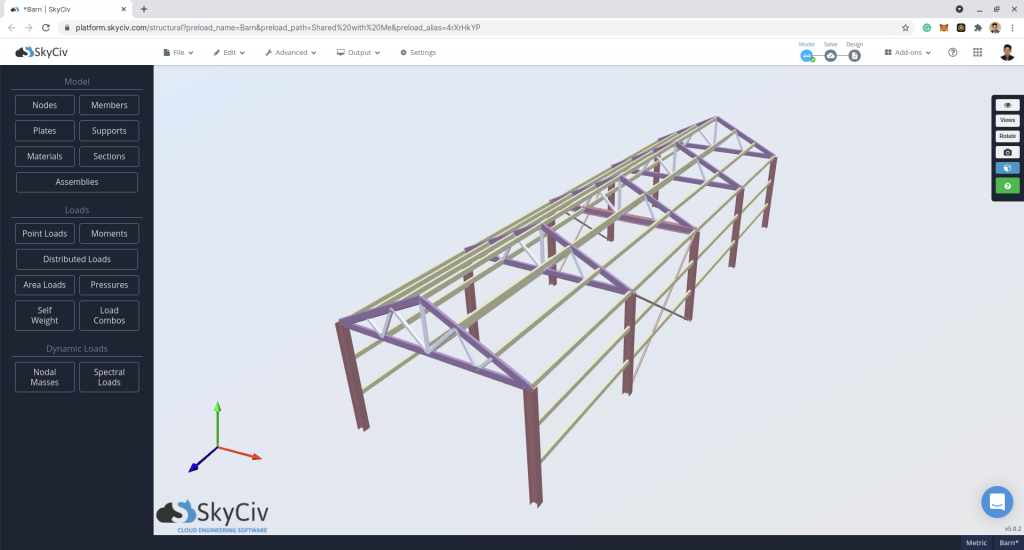
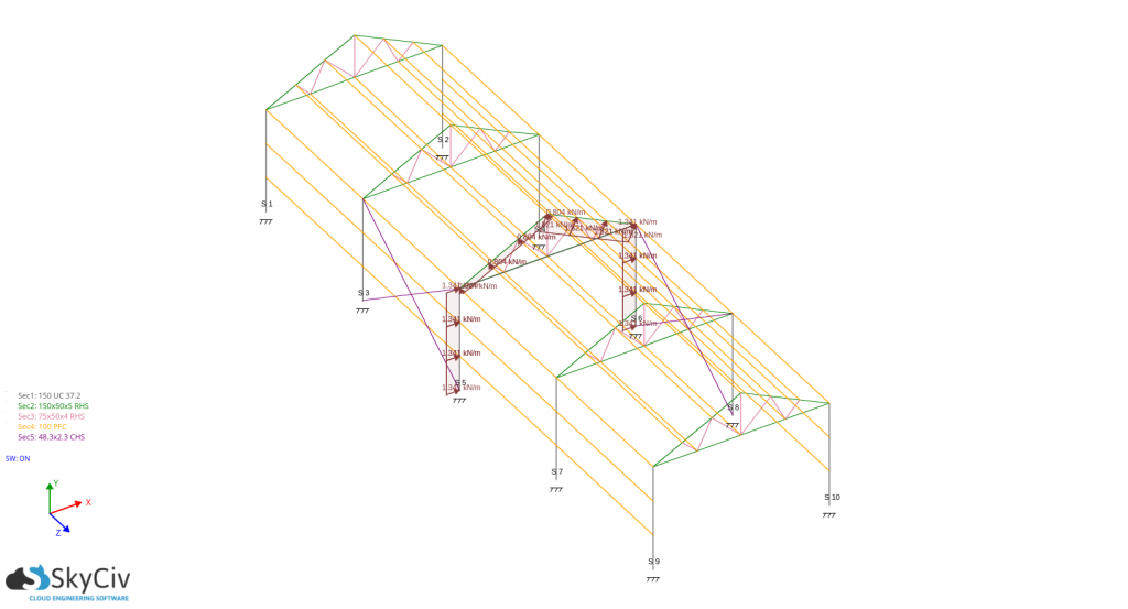
記事上で, ワルワンの建物の風荷重圧力の計算例, マハラシュトラ, インド (18.945695°N, 74.564866°E) 表示されます. この計算は IS に従って行われます。 875-3:2015 風荷重計算. SkyCiv無料風荷重計算機 最近ISを追加しました 875-3 風荷重計算, したがって, 風荷重を計算する方法を示します, 以下の S3D Barnhouse モデルを使用して:
このケーススタディの場合, 構造データは以下の通りです:
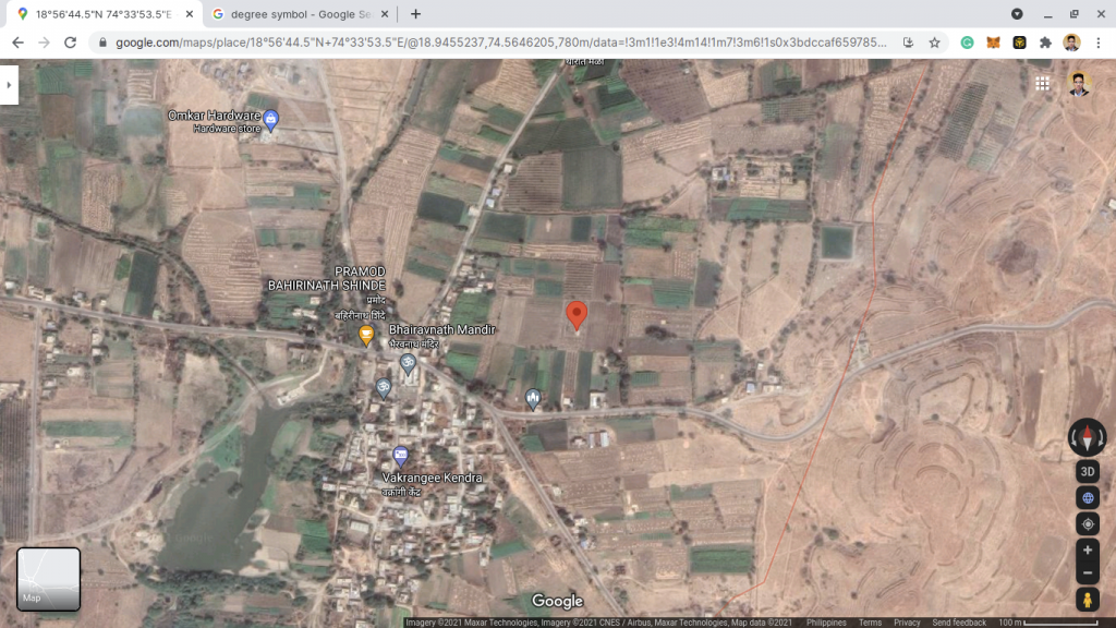
| ロケーション | 反撃, マハラシュトラ, インド (18.945695°N, 74.564866°E) |
| 占有 | その他 – 農場の構造 |
| 地形 | 平坦な空き地 |
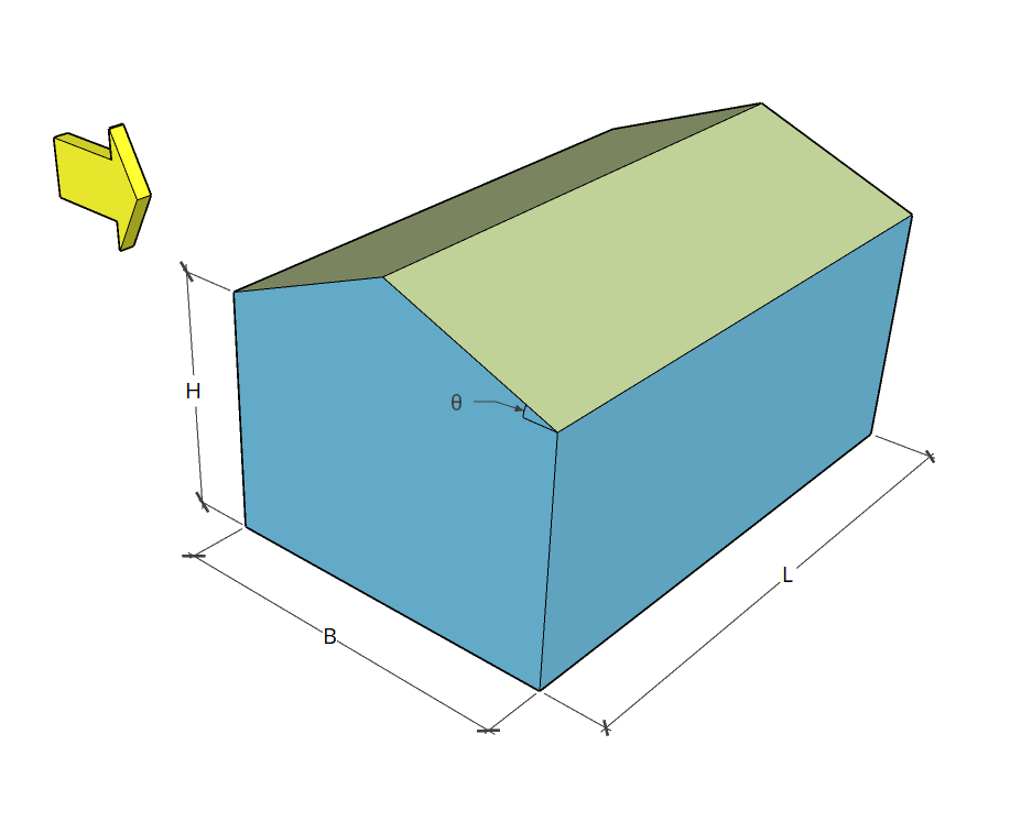
| 外形寸法 | B = 4 m × L = 14 計画中のm H = 庇高さ 2.4 メートル 標高での頂点の高さ. 3.4 メートル 屋根の傾斜 1:2 (26.565°) 開口部なし |
| クラッド | 母屋の間隔は 0.745m 壁の間柱の間隔は 0.8m |
IS の使用 875-3: 2015, その場所の設計風速と傾斜屋根の長方形の建物の設計風圧は、以下の方程式を使用して解くことができます。:
設計風速 高所で と (m/sで): V と = Vbk1k2k3k4 (1)
どこ:
V b それは基本風速, MS
k1 それは 確率係数 (リスク係数) に基づく 6.3.1 ISの 875-3
k2 それは 地形の粗さと高さの係数 に基づく 6.3.2 ISの 875-3
k3 それは 地形要因 に基づく 6.3.3 ISの 875-3
k4 それは 重要度 に基づくサイクロン領域の 6.3.4 ISの 875-3
設計風圧 (Paで): pd = KdKaKcpと (2)
どこ:
Kd それは 風向性係数 に基づく 7.2.1 ISの 875-3. に等しい 1.0 局所圧力係数を考慮する場合.
Ka それは 面積平均係数 に基づく 7.2.2 ISの 875-3
Kc それは 組み合わせ係数 に基づく 7.3.3.13 IS 875-3
pと に等しい 0.60V と2 Paで
=建物またはその他の構造物の場所での地面からの高さ pd 以下のものを摂取すべきではない 0.70pと
設計圧力から pd 得られた, 圧力は、を使用してメンバーに分散されます。:
表面または部材にかかる風力 (宿): F = (Cオン – Cパイ)アプd (3)
どこ:
あ 構造要素または被覆ユニットの表面積です。
Cオン は外部圧力係数です
Cp私 は内圧係数です
以下の各パラメータの詳細を詳しく説明します.
基本風速 V b
図から 1 ISの 875-3, サイトの位置は基本風速が吹く地図の状況です V b に等しい 39 MS.
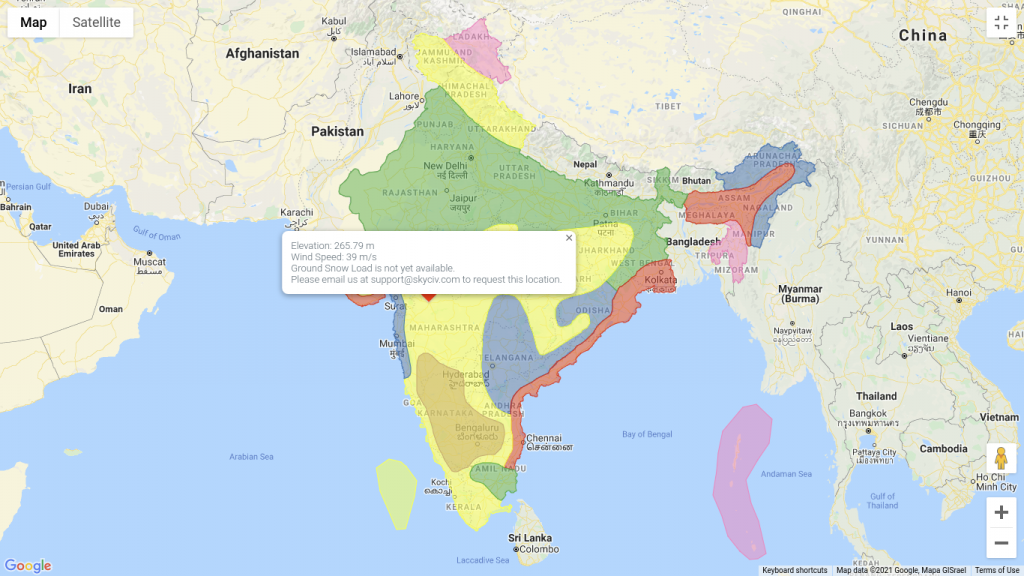
SkyCivは、インドのサイトの場所を定義するだけで風速計算を自動化できます. 私たちを試してみてください SkyCiv Free Wind Tool.
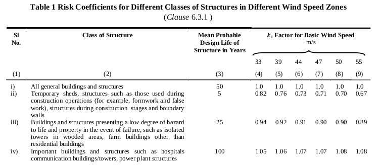
確率係数 (リスク係数) k1
テーブル 1 ISの 875-3 異なる風速帯における異なるクラスの構造物のリスク係数を示します。. この構造の場合, それは納屋であり、いくつかの家畜を保護するために使用されるため, 構造は以下に分類されます “故障した場合でも生命や財産に対する危険性が低い建物および構築物, 樹木が茂った地域の孤立した塔など, 住宅以外の農場の建物。” したがって, 表から 1 ISの 875-3, 対応します 確率係数 (リスク係数) k1 に等しい 0.92.
地形の粗さと高さの係数 k2
この構造の場合, 農場の中心に位置し、すぐに障害物がない場所です。. したがって, 地形は次のように分類できます カテゴリー 1. テーブルの使用 2 ISの 875-3:2015, 私たちは得ることができます k2 値 (考慮される高さによって異なります):
| 高さ | k2 |
| 基準高さ, H = 2.4 メートル | 1.05 |
地形要因 k3
地形効果を考慮するため, 8 つの場所の標高データを取得する必要があります。 (8) 枢機卿の方向 – N, S, W, E, 北西, 生まれ, SW, とSE – Google 標高 API を使用する. データに基づいて, 一般に地形は次のように仮定できます。 “平らな” 全方向に. したがって, に基づく 6.3.3 ISの 875-3:2015, 私たちは設定することができます k3 に等しい 1.0.
重要度 k4
敷地の場所はインドの東海岸内ではなく、構造物は農業目的にのみ使用されるため、, の価値 k4 に等しい 1.0 に基づく 6.3.4 ISの 875-3:2015
設計風速 V と
上記の要因から, 設計風速はすでに解決できています V と 式を使用する (1):
| レベル | V b MS | k1 | k2 | k3 | k4 | V と MS |
| H = 2.4 メートル | 39.0 | 0.92 | 1.05 | 1.0 | 1.0 | 37.674 |
設計風速より, 設計風圧を計算できます pd.
風向係数 Kd
から 7.2.1 ISの 875-3:2015, の 風向係数 Kd に等しい 0.9 フレームの場合、および局所的な圧力係数を考慮する場合, に等しくなります 1.0. この例では, 我々は使用するだろう Kd に等しい 1.0 母屋や壁の研究用、 Kd に等しい 0.9 柱とトラスの場合.
範囲 平均化係数 Ka
の 範囲 平均化係数 Ka テーブルを使用して計算できます 4 ISの 875-3:2015:
Ka = 1.0 以下の面積の場合 10 平方メートル.
Ka = 0.9 に等しい面積 25 平方メートル.
Ka = 0.8 面積以上 100 平方メートル.
=建物またはその他の構造物の場所での地面からの高さ Ka 値の間を線形補間できる. この構造の場合, 風上の列の支流領域を取得する必要があります (ゾーンA), 風下 (ゾーンB), サイドウォール (ゾーン C および D), と屋根のトラス. しかも, また、壁の間柱と母屋の支流の面積も考慮します。.
| 成分 | 範囲, 平方メートル. | Ka |
| カラム | 2.4×3.5 m = 8.4 平方メートル. | 1.0 |
| トラス | 4×3.5 メートル (投影) = 14 平方メートル. | 0.97 |
| 壁鋲 | 0.8×3.5 m = 2.8 平方メートル. | 1.0 |
| 母屋 | 0.745×3.5 m = 2.608 平方メートル. | 1.0 |
組み合わせ係数 Kc
壁や屋根の圧力と内部の圧力の同時作用を考慮しますので、, 想定される 組み合わせ係数 Kc に等しい 0.9 で参照されているように 7.3.3.13 ISの 875-3:2015.
設計風圧, pd
方程式の使用 (2), 設計風圧を計算できます, pd, =建物またはその他の構造物の場所での地面からの高さ pと = 851.598 上手 そして pd 以下であってはなりません 0.7pと または 596.119上手.
| 成分 | Ka | Kd | Kc | pと | pd |
| カラム | 1.0 | 1.0 | 0.9 | 851.598 | 766.438 |
| トラス | 0.97 | 1.0 | 0.9 | 851.598 | 743.445 |
| 壁鋲 | 1.0 | 1.0 | 0.9 | 851.598 | 766.438 |
| 母屋 | 1.0 | 1.0 | 0.9 | 851.598 | 766.438 |
これらのデータから, 設計圧力をコンポーネントに分配するには、圧力係数を計算する必要があります。.
内圧係数 Cパイ
の 内圧係数 Cパイ から決定できます 7.3.2 ISの 875-3:2015. この構造の場合, 壁の総開口部は 5 総壁面積のパーセント. したがって, の Cパイ この例の値は次のとおりです。 +0.2 そして -0.2.
外部圧力係数 Cオン
の 外部圧力係数 Cオン 身長などの特定のパラメータに依存します, 幅, 長さ, 屋根の角度, と屋根のプロファイル.
壁外圧係数
壁の外圧係数は次によって異なります。 ハードウェア そして リットル/ワット 比, どこ h 軒の高さです, w 建物の最小寸法です, そして l 建物の大きい方の寸法です. この例では, h = H, l = L, そして w = B. したがって, ハードウェア = 0.6 そして l/w = 3.5. テーブルから 5 ISの 875-3:2015, 対応します Cオン 値は次のとおりです:
風角 = 0 度:
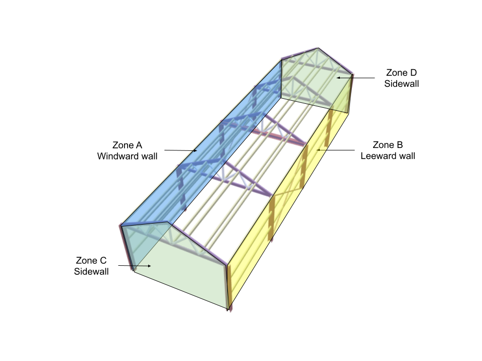
| ゾーン/サーフェス | Cオン |
| ゾーンA – 風上壁 | +0.7 |
| ゾーンB – 風下の壁 | -0.3 |
| ゾーンC – 側壁 | -0.7 |
| ゾーンD – 側壁 | -0.7 |
| ローカルゾーン (0.25w 端から) | -1.1 |
風角 = 90 度:
| ゾーン/サーフェス | Cオン |
| ゾーンA – 風上壁 | -0.5 |
| ゾーンB – 風下の壁 | -0.5 |
| ゾーンC – 側壁 | +0.7 |
| ゾーンD – 側壁 | -0.1 |
| ローカルゾーン (0.25w 端から) | -1.1 |
=建物またはその他の構造物の場所での地面からの高さ w = 4 メートル.
屋根外圧係数
この構造の場合, 屋根の形状が切妻またはデュオピッチであるため, 屋根の外圧係数は表に基づいて計算されます。 6 ISの 875-3:2015. この例では、 ハードウェア = 0.6, そして屋根の角度は 26.565°, の Cオン 値は次の値を使用して補間されます。:
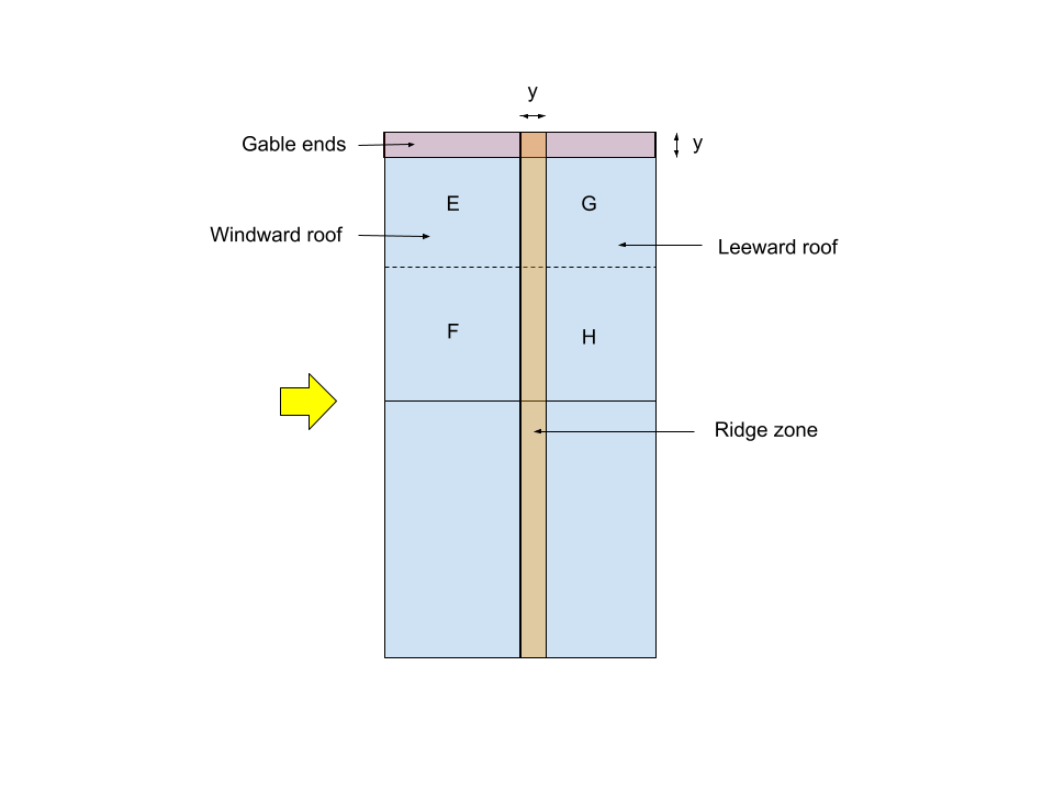
注意: そして = 0.15w = 0.6メートル
風角 = 0 度:
| 屋根の角度 | ゾーンEF – 風上 | ゾーンGH – 風下 |
| 20° | -0.7 | -0.5 |
| 26.565° | -0.109 | -0.5 |
| 30° | -0.2 | -0.5 |
風角 = 90 度:
| 屋根の角度 | ゾーンEG – 横風 | ゾーンFH – 横風 |
| 20° | -0.8 | -0.6 |
| 26.565° | -0.8 | -0.6 |
| 30° | -0.8 | -0.6 |
局所的な圧力に対して:
| 屋根の角度 | 切妻端 | リッジゾーン |
| 20° | -1.5 | -1.0 |
| 26.565° | -1.172 | -1.0 |
| 30° | -1.0 | -1.0 |
最終的な屋根の圧力係数は次のようになります。:
| ゾーン/サーフェス | 風向き – 0 度 | 風向き – 90 度 |
| ゾーンEF – 風上 | -0.109 | – |
| ゾーンGH – 風下 | -0.5 | – |
| ゾーンEG – 横風 | – | -0.8 |
| ゾーンFH – 横風 | – | -0.6 |
| 切妻端 | -1.172 | -1.172 |
| リッジゾーン | -1.0 | -1.0 |
内圧と外圧を合わせた圧力
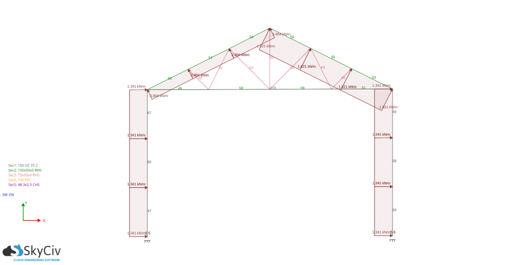
上記の値から, 風力は次の式を使用して計算できます。 (3). しかしながら, 簡単にするために, デザインプレッシャーを受けるだけです (値を面積に乗算しない あ) も検討する予定です 風向角 0 度 メインフレーム用 (柱とトラス). フレーム間隔は以下に等しい 3.5メートル. =建物またはその他の構造物の場所での地面からの高さ pd = 766.438 上手 柱と壁の間柱の両方に.
柱や壁の間柱に – 0 度:
| ゾーン/サーフェス | Cオン | Cパイ | Cオン–Cパイ | p = pd(Cオン-Cパイ) 上手 | コラム用 p×3.5m N / m | 壁スタッド用 p×0.8m N / m |
| ゾーンA – 風上壁 | 0.7 | +0.2 -0.2 | +0.5 +0.9 | 383.219 689.795 | 1341.267 2414.281 | 306.575 551.836 |
| ゾーンB – 風下の壁 | -0.3 | +0.2 -0.2 | -0.5 -0.1 | -383.219 -76.644 | -1341.267 -268.253 | -306.575 -61.315 |
| ローカルゾーン (1端からメートル) | -1.1 | +0.2 -0.2 | -1.3 -0.9 | -996.370 -689.795 | -3487.295 -2414.281 | -797.096 -551.836 |
均一な荷重を得るために、柱にかかる圧力は 3.5 m に倍増されます。. しかも, 壁の間柱用, 0.8mが掛けられます. 正の圧力は表面に向かって作用し、負の圧力は表面から離れるように作用することを意味することに注意してください。 (吸引).
トラスおよび母屋用 – 0 却下:
| ゾーン/サーフェス | Cオン | Cパイ | Cオン–Cパイ | p = pd(Cオン-Cパイ) 上手 | トラス p×3.5m N / m | 母屋 p×0.745m N / m |
| ゾーンEF – 風上 | -0.109 | +0.2 -0.2 | -0.309 +0.091 | -229.725 67.654 | -804.036 236.787 | -171.145 50.402 |
| ゾーン GH – 風下 | -0.5 | +0.2 -0.2 | -0.7 -0.3 | -520.412 -223.034 | -1821.441 -780.617 | -387.707 -166.160 |
| 切妻端 | -1.172 | +0.2 -0.2 | -1.372 -0.972 | -1051.553 -744.978 | -3680.437 -2607.423 | – |
| リッジゾーン | -1.0 | +0.2 -0.2 | -1.2 -0.8 | -919.726 -613.151 | -3219.041 -2146.027 | – |
均一な荷重を得るために、トラスにかかる圧力は 3.5 m に倍増されます。. しかも, 壁の間柱用, 0.745mが乗算されます. =建物またはその他の構造物の場所での地面からの高さ pd = 766.438 上手 母屋用と pd = 743.445 上手 トラス用.
1 つのクリティカル フレームを考える – 間隔は3.5mです:
ために pd(Cオン – +Cパイ):
ために pd(Cオン – -Cパイ):
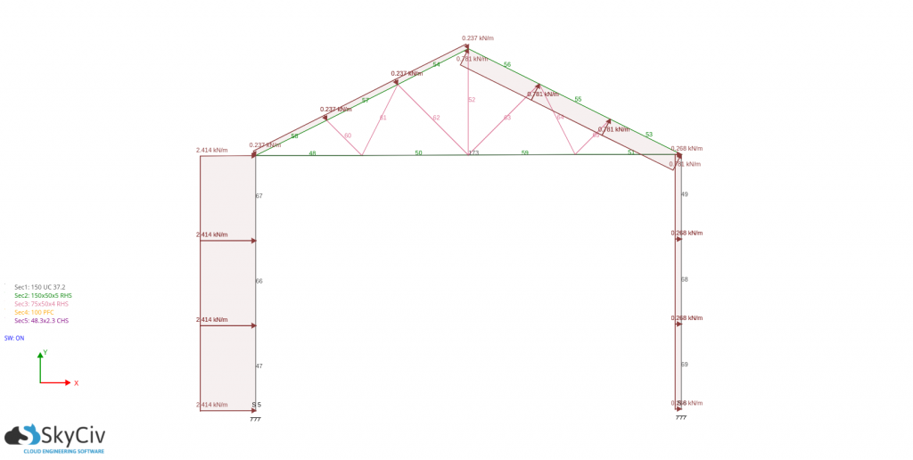
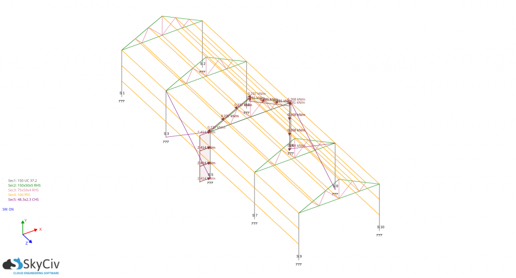
壁の間柱と母屋の設計用, 必要なのは、それに作用する絶対最大圧力を取得し、それを設計力の計算の基礎として使用することだけです。. この場合, 設計風荷重は: -797.096 壁スタッドの場合は N/m、母屋の場合は -783.407N/m,
これらの計算はすべて、 SkyCiv のロード ジェネレーター ソフトウェア ISの場合 875-3 他のコードも同様に. ユーザーはサイトの場所に入力して、風速と地形要素を取得できます, 建物パラメータを入力して風圧を生成する. 私たちを試してみてください SkyCiv Free Wind Tool 切妻構造の風速と風圧の計算用.

構造エンジニア, 製品開発
MS土木工学
参考文献:
- 設計荷重 (地震以外) 建物および構造物向け — 実践規範 (部 3 風荷重編). (2015). インド規格局.