モデル化の方法, SkyCivを使用してスチールモーメントフレームを分析および設計する
このチュートリアルは、統合された SkyCiv モジュールを使用したモーメント フレーム設計プロセスの簡単なガイドです。: 構造3D, メンバーデザイン, と接続設計.
モーメント フレームは、部分的または完全に拘束された接続で接続された柱と梁の組み合わせです。. これらの接続にはモーメント力がかかります 単純にサポートされる条件とは見なされない. それらは、せん断壁やブレース付きフレームと同様に使用されます; それらは、垂直方向の力と併せて横方向の力に抵抗します. 固定された性質のため, フレーム メンバー’ 剛性は、フレームの横方向の剛性の主な原因です. ブレース付きフレームは通常、必要な材料に基づいて安価なオプションです, しかし、モーメント フレームは、建築家や設計者に柱の間に広いスペースを与えるため、美観が向上します。. 次の記事は次の内容で構成されています:
- モーメント フレームのモデリング
- モーメント フレームを読み込んでいます
- あなたの瞬間を分析する フレーム
- AISC に従って鉄骨部材を設計する 360
- SkyCiv接続を使用して接続を設計する, AISCによる 360
SkyCiv構造3D (S3D): モーメント フレームのモデリングと分析
モデリング
モデリング用, 私たちは使用します SkyCiv構造3D 分析ソフトウェア (SkyCivのホームページで無料で始めましょう). しかし、モデリングに入る前に, どのユニットで働いているかを確認してください. これは、に行くことによって行うことができます 設定 ツールバーの右上に. この例では, 私たちは帝国単位で活動します. シングル ベイ モーメント フレームの重心ビームの高さが 18 足と 30 足幅. また, モーメント フレームは AISC データベースの W 形状で完全に構成され、ASTM A992 Gr から製造されていると仮定します。. 50 鋼. 最後に, のトライアルコラムとビームサイズ 幅12×40 そして 幅18×65 使用されます, それぞれ,
ワークフローを開始するには, モーメントフレームのノードを入力しましょう. 右から左に、選択ボックス内に完全に含まれている要素のみが選択されます ノード 入力タブで (画面の左側). フレームのノードは (バツ,そして): (0,0), (30,0), (0,18), そして (30,18).
次に、フレームを構成する 2 つの柱と梁を生成します。. これをする, 2つのオプションがあります: 1) に行く 会員 入力タブで、各メンバーの終了ノードを入力するか、 2) を使用してメンバーを描画します ペンツール モデル空間の右側の垂直ツールバーにあります. 瞬間フレームで作業しているため, 各接続位置での各メンバーのエンドリリースは完全に修正する必要があります, として示される “FFFFFF” として強調表示されます “フレーム” 内でメンバーを作成するとき 会員 タブ. これまでの瞬間フレームを見てみましょう:
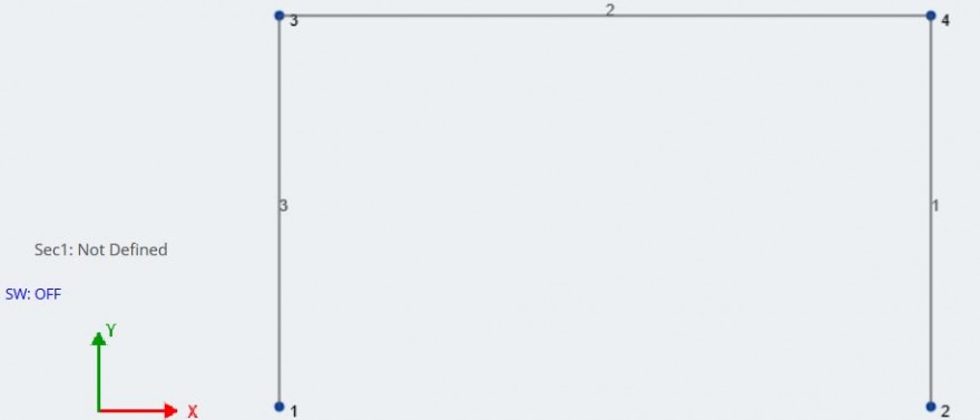
知らせ, “Sec1” 現在のメンバーに適用されるセクションであり、 “定義されていません” まだセクションを適用していないため. メンバーにセクションを割り当てる前に, モデルに正しい鋼材をインポートしましょう. 右から左に、選択ボックス内に完全に含まれている要素のみが選択されます 材料 – データベース 入力タブで. 正しい材料が見つかるまで、各相対フィールドのドロップダウンに従ってください。:
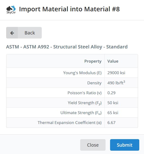 送信をクリックして素材をインポートします. 必要な素材をインポートした後, メンバーのサイズを割り当てましょう. 右から左に、選択ボックス内に完全に含まれている要素のみが選択されます セクション 入力タブで、ビルダーをクリックします. 今, の範囲内で活動している SkyCivセクションビルダー モジュール, S3D の現在のプロジェクトに直接統合. セクション ビルダーの使用中, に移動して、2 つの W 形状をインポートします。 データベース セクションビルダーの部分と各形状の選択. クリックする前に 繰り返し間の距離, 右側のマテリアルが、両方のメンバーに関連付けたいマテリアルに設定されていることを確認してください: ASTM A992 スチール.
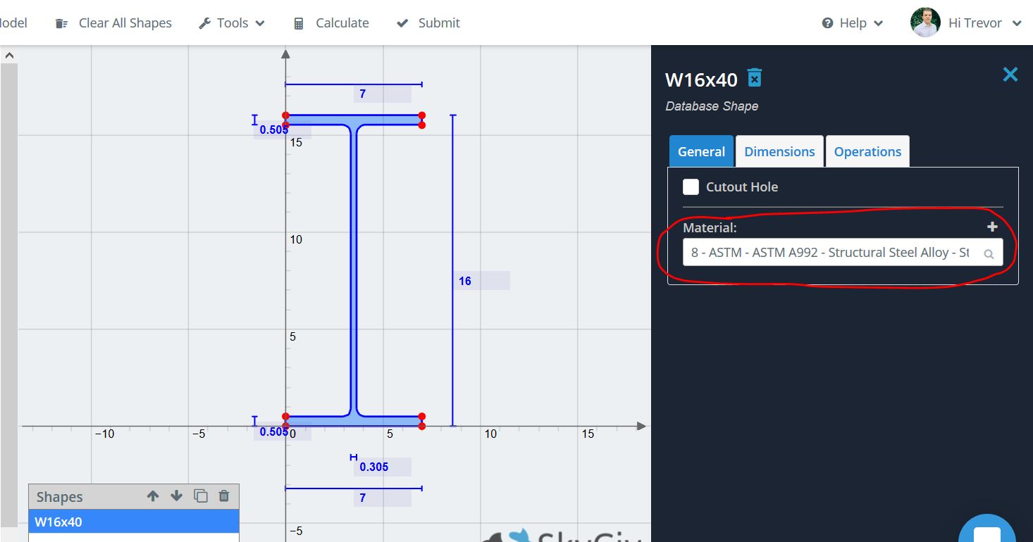
2 つのセクションをモデルに取り込んだ後, を使用して各メンバーに割り当てます。 セクションID 各メンバーが選択されている間の入力タブのフィールド. 詳細については、 SkyCivセクションビルダー とその能力, そのソフトウェアドキュメントをチェックしてください.
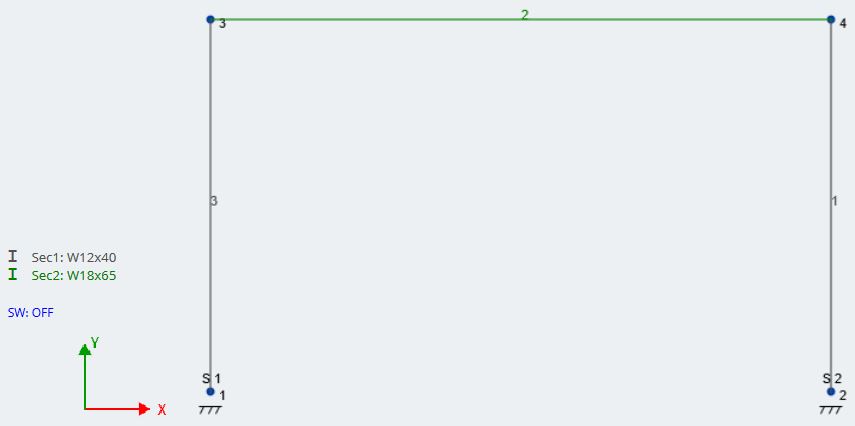
最後に、サポート条件を適用する必要があります. 重力柱またはブレース付きフレームの柱部分とは異なります, 当社のコラム サポートは完全に固定する必要があるため、ベースでモーメントが発生します。. サポートを追加するには, NS + 両方のノードをクリックします, 右クリックしてから左クリック サポートを追加. 入力タブに移動します – すでにノードが選択されています – 固定支持条件を選択. これは、に行くことによっても行うことができます サポート 入力タブで、各ノードにサポートを適用します.
棒モデルは、サポートに加えて、柱と梁の 2 つの異なる部材を表示するはずです。:
私たちの瞬間フレーム, また、カラムの向きが正しく、横方向のアクションに適していることを確認する必要があります. モーメント フレームは横方向の力を受けるため、, 柱の強軸は、ほとんどの場合、荷重方向に対して垂直です。. この場合, 横方向の力は X 方向になります, そのため、柱フランジは X 方向に垂直である必要があります. メンバーの向きを確認する良い方法は、3D レンダリングを入力することです。. これをする, モデル空間の右側のツールバーに移動し、3D 立方体のような形状をクリックします, モデルの 3D レンダリングが表示されます. 3D でモーメント フレームを見てみましょう:
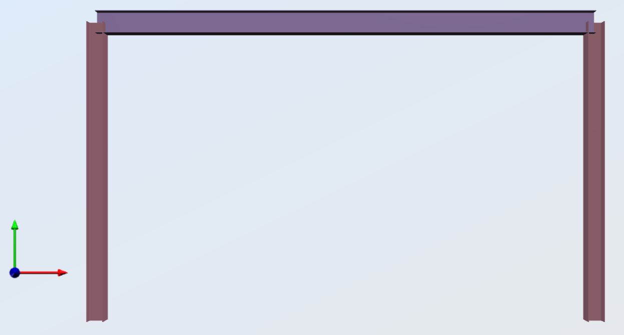
列が正しい方向に向けられていることがわかります. より複雑な 3D 構造では、メンバーを選択することで、任意のメンバーの向きを回転できます。, クリックする 高度な, 次に、目的の回転を度単位で入力します 回転角 分野.
構造をロードする前に, 正しいサポートがあることを再確認してください, セクション, および各セクションの資料.
負荷と負荷の組み合わせ
知らせ, 以前の図では、自重がオフになっていました, 今すぐこれをオンにしましょう. クリックしてください “SW: オフ” モデル空間で自重入力タブを出してONにする. SkyCiv は、分析計算を行う際に各メンバーの自重を考慮に入れるようになりました.
実用的な目的のために, モーメント フレームが、梁の間隔が 2 である建物にあると仮定します 8 フィート. したがって, ワンウェイロード用, 私たちの支流の幅は 8 フィート. 重ね積み用, 私たちの瞬間フレームが次の非因数負荷を受けると仮定しましょう:
\(側面:風:Load=8\:キップ:@\:トップ:elevation\)
\(Dead\:Load=40\:psf)
\(40\:psf*8\:ft=320\:lb/ft=0.320\:k/ft\)
\(住む:Load=100\:psf)
\(100\:psf*8\:ft=800\:lb/ft=0.800\:k/ft\)
モーメントフレームが対称であるため, 1つの風向だけを見ていきます. フレームがさまざまな方向にさまざまな大きさの風荷重を見る場合, その風荷重ケースも追加する必要があります.
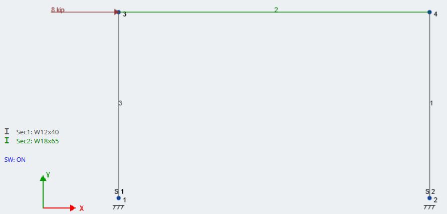
風による横方向の点荷重から始めましょう. 右から左に、選択ボックス内に完全に含まれている要素のみが選択されます 点荷重 左側の入力タブで. 適用します 8 ノードへのkipロード 3 X方向に. その後, 入力して、対応する荷重グループを追加します “風荷重” に 負荷グループ フィールドと打撃 受け入れる. 風荷重は次のようになります:
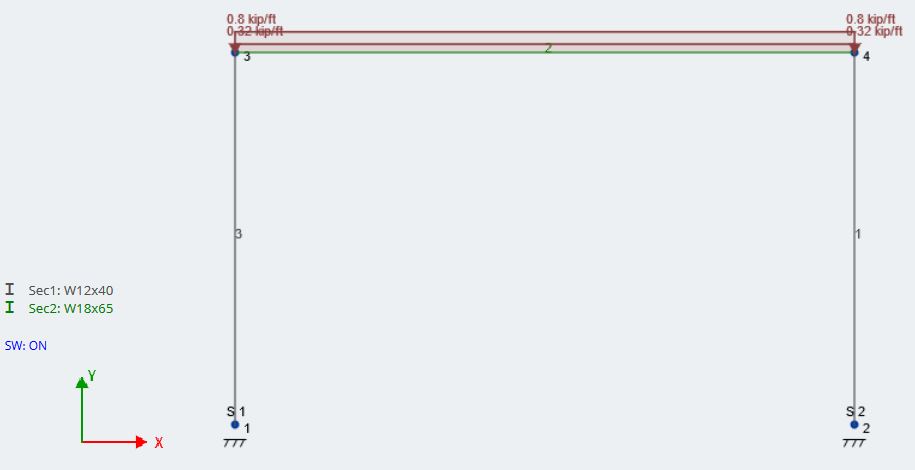
次, 重ね合わせた固定荷重と活荷重を均一な分布荷重として適用してみましょう. 右から左に、選択ボックス内に完全に含まれている要素のみが選択されます 分布荷重 そして会員IDを入力 (メンバー 2) 私たちのビームのために. その後, の中に Y-Magを開始します そして Y-Magを終了します, の大きさを入力 0.320 死荷重の k/ft. 風荷重と同様, タイプ “デッドロード” の中に 負荷グループ 対応する荷重グループを生成するフィールド. ライブ ロードに対してこのプロセスを繰り返します。. デッド ロードとライブ ロードの両方が適用されたモデルの外観を次に示します。:
解析前の最後の主要なステップは、荷重の組み合わせを生成することです. SkyCiv は、ユーザーが世界中の国のコードから負荷の組み合わせを直接インポートする機能を提供します. インペリアル単位と AISC 形状で作業しているため, ASCE から荷重の組み合わせをインポートします。 7-10. まず最初に, 荷重グループを荷重ケースに割り当てる必要があります. 上部のツールバーに移動し、 編集する – 荷重ケースの割り当て. 各荷重グループを正しい荷重ケースに割り当てます. この例では, それは単に死荷重を死荷重に合わせているだけです, 等. 割り当ては次のようになります。:
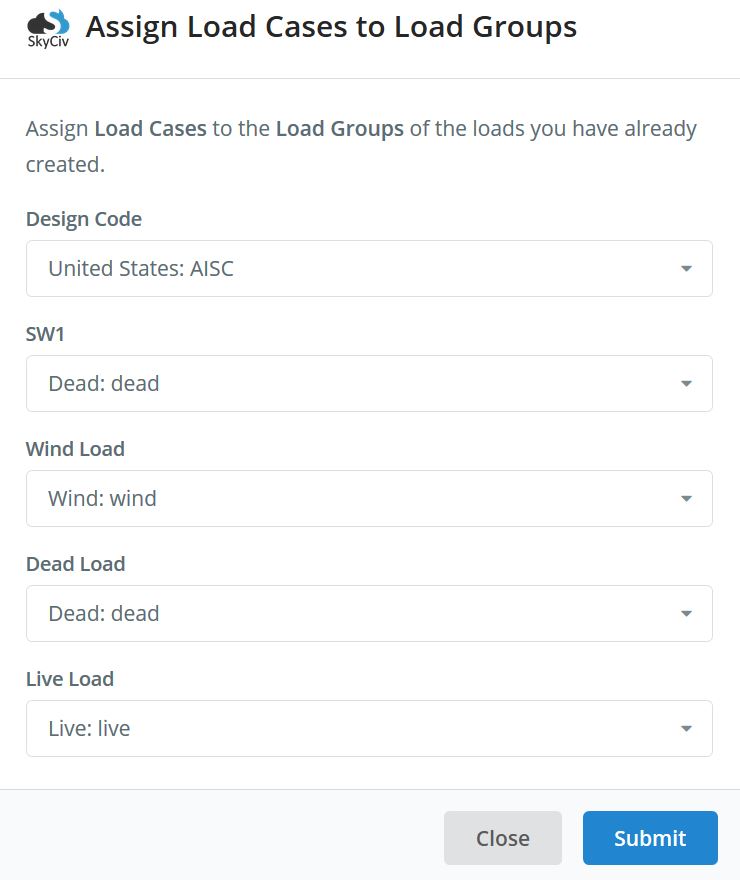
荷重ケースを自重に割り当てる必要があることに注意してください (SW1) 同様に. 荷重の組み合わせを生成するには、 コンボをロードする 入力タブで、をクリックします デザインコード. この場合、LRFD 設計を使用します。. 画面 負荷の組み合わせと、これが表示されるはずです:
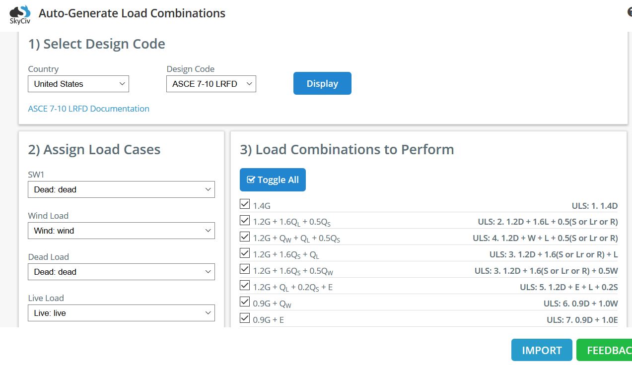
インポート前に荷重ケースを割り当て忘れた場合, ここでもそれを行うことができます. 当社の負荷組み合わせジェネレーターは、あらゆる ASCE をプルします。 7-10 プロジェクトの荷重ケースの少なくとも 1 つを含む荷重の組み合わせ. 私たちの場合には, 地震荷重はありません, ULSのチェックを外します: 5 とユニバーサル: 6. また、ルーフ ライブまたはスノー ロードもありません。, 1.2D + 1.6L 荷重の組み合わせが垂直方向の力を支配します, ULSのチェックを外します 3. 必要な負荷の組み合わせを確認したら, クリック インポート それらをプロジェクトにインポートします.
ノードを生成したので、, 会員, サポート, 負荷, 荷重ケース, 荷重の組み合わせ, 分析を開始できます. これらの手順または S3D の使用に関する情報については、, 私たちをチェックしてください ソフトウェアのドキュメント.
分析, 結果, および後処理
に行くのは良い習慣です 編集する – 修理モデル 構造の分析を開始する前に、モデル内の不整合を修復するか、ノードをマージします。. また, エンド リリースとサポート条件を全体にわたってチェックして、プロジェクトが安定していることを確認します。. 最後に, に行く 設定 – ソルバー 関連する分析設定を確認して編集する, P-デルタ分析中の収束許容誤差やメンバーごとの評価点数など.
この例には動的ローディングが含まれていないため、, 使用できる3つの解決方法があります:
- 線形静的
- 線形静的 + 座屈
- 非線形静的 + Pデルタ
SkyCiv Structural 3D の各解析タイプについて詳しく知るには, ここをクリック.
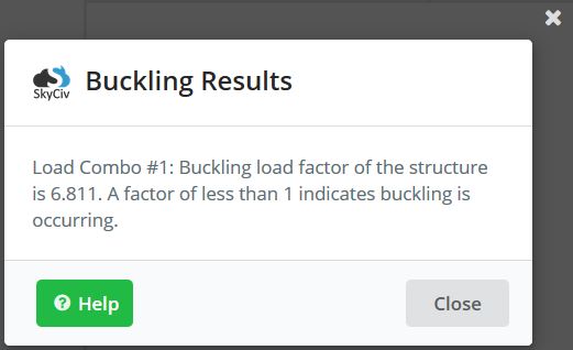
少なくとも、Linear Static を実行することをお勧めします。 + 構造内のいずれかのメンバーが座屈の影響を受けているかどうかを確認するための座屈解析. 非線形静的を使用します + 横風荷重による二次効果によるPデルタ解析. カーソルを合わせた後、ドロップダウンで分析オプションを見つけます 解決する, 上部ツールバーにあります. 結果を生成した後, フレームの座屈の心配がないことがわかりました, 座屈解析プロンプトのおかげで:
結果ページの左側には、さまざまなタイプの力と表示可能な結果が表示されます。. 個々の負荷の組み合わせを評価可能, 個々の荷重ケースまたはグループと同様に. 設計目的のため, を使用します 封筒絶対最大 各メンバーが経験する最悪の力を見せてくれるから. 注意, エンベロープは最悪の負荷の組み合わせを示していません, しかし、一度にすべての負荷の組み合わせの中で最悪の組み合わせ. この負荷条件は現実的ではありません, しかしそれ “封筒” 各メンバーが持つすべての可能な力 できる 見る. モーメント フレームに関連する力とたわみの図については、下の図を参照してください。:
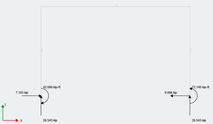
反応エンベロープ絶対最大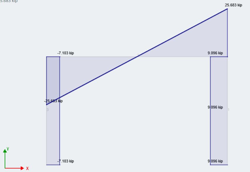
せん断エンベロープ絶対最大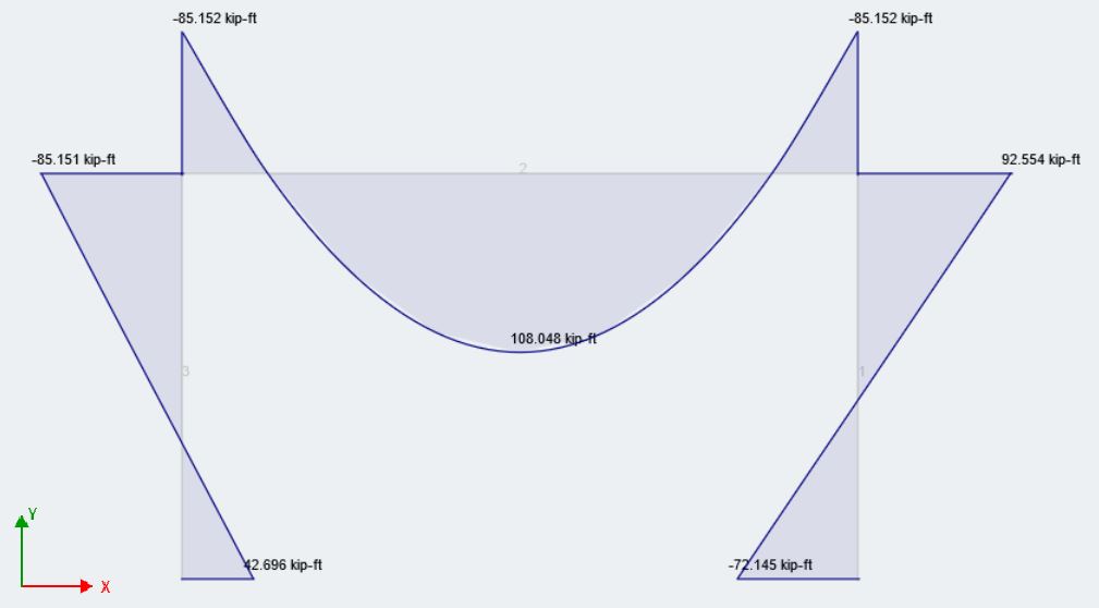
モーメントエンベロープ絶対最大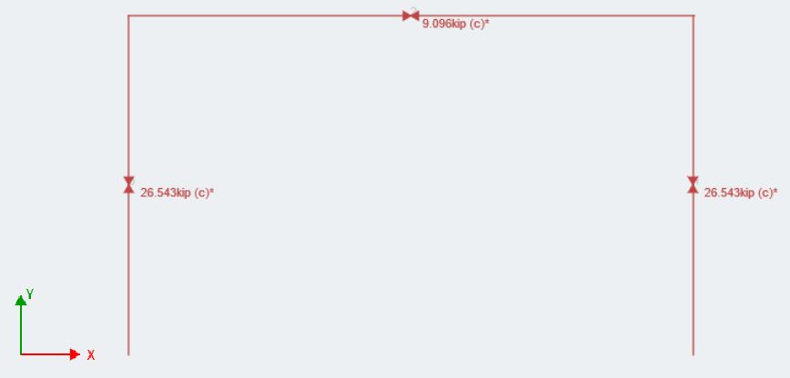
軸エンベロープ絶対最大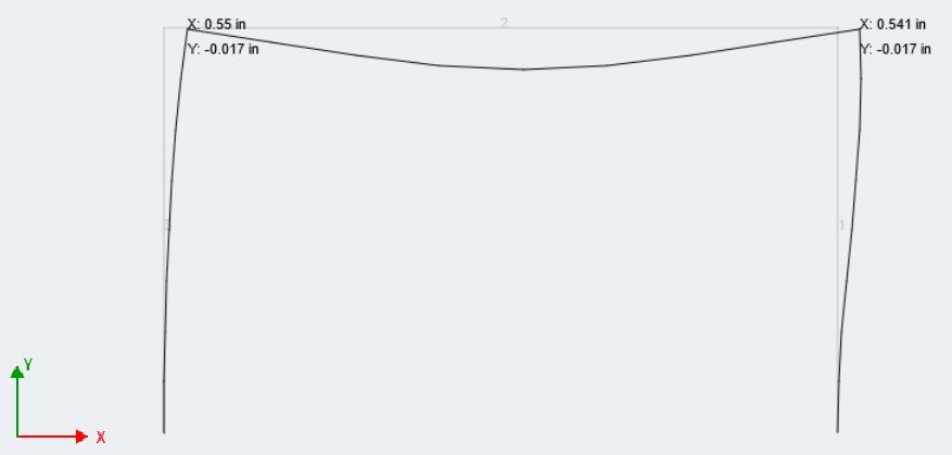
たわみエンベロープ絶対最大
地震荷重によるものではないストーリードリフトの直接的なコード要件はありませんが、, 間の構造のストーリードリフトを維持することをお勧めします 1/500 そして 1/200 物語の高さ (エリングウッド). このフレームの場合, 物語の高さは 18 フィート, だから私たちのドリフトは間にあるはずです (18 フィート/500) そして (18 ft/5200), または間 0.43 そして 1.0 インチ. エンベロープの最大ドリフトは次のように示されます 0.55 インチ, これは実際には H/500 の下限に近い, これは私たちの工学的判断を満たすものです.
ボタン, 結果概要, メンバーのストレス限界をすばやく確認するために、大多数のユーザーが使用しています, 特に鋼の場合. このウィンドウには、応力容量に最も近い部材のスナップショットが表示されます. ユーザーは、モデリング スペースの右側にあるツールバーを使用して、プロジェクトの応力とたわみの制限をカスタマイズできます。. これは、 結果概要: 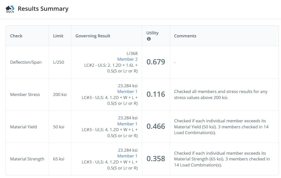 の たわみ/スパン そして 部材応力 カスタマイズ可能なフィールドです. 最後に, Structural 3D がユーザーに次の機能を提供することを忘れないでください。 ほぼ無制限の機能とカスタマイズでレポートを印刷.
SkyCiv スイートを使用する最大の利点の 1 つは、すべてのモジュールをスタンドアロンとして使用できることです。, それらのほとんどは直接統合されており、構造 3D から直接使用する方が適しています。. こちらです, 計算したばかりのすべての分析結果は、メンバーと接続の設計のために補助モジュールに直接取り込むことができます.
SkyCivメンバーデザイン: デザインの確認と選択 メンバー
SkyCiv全体で行われた作業の大部分はモデリングです, 読み込み中, および 3D モデルの解析フェーズ. SkyCivメンバーデザインは、使いやすさとシンプルさを重視するという点で同様のスタイルに従います. 使いやすく、S3D との統合により、ユーザーはモデルと設計モジュールをシームレスに切り替えることができます. ユーザーが時間をかけて各設計モジュールを調べ、自分でこれを確認することをお勧めします. 今, フレーム内のメンバーのデザインを見てみましょう; 私たちは使用します AISC 360-10 LRFD 私たちのデザインコードのために.
メンバーデザインモジュールを開いたとき, プロジェクトのジョブの詳細が表示され、変更および確認できます. 次の入力タブでは、鋼のファイファクターをカスタマイズできます. AISC によってレイアウトされたデフォルトを維持します。. の 会員 入力タブは、設計可能なメンバーのリストを停止して確認するのに適した場所です. SkyCivの統合エコシステムのため, 3D モデルのすべての鉄骨部材をインポートし、ブレースなしの長さを計算します。, 有効長さ係数, それらの細さの比率. また、モデルに存在する材料とさまざまなセクションもリストします. フォース 任意の単一荷重の組み合わせを設計するオプションを提供します, ただし、構造のエンベロープ力にデフォルト設定されています. 任意の荷重の組み合わせについても、構造の絶対的な最悪ケースの力を表示できます.
入力オプションを確認したので、, させて 実行設計, この出力が表示されるはずです:
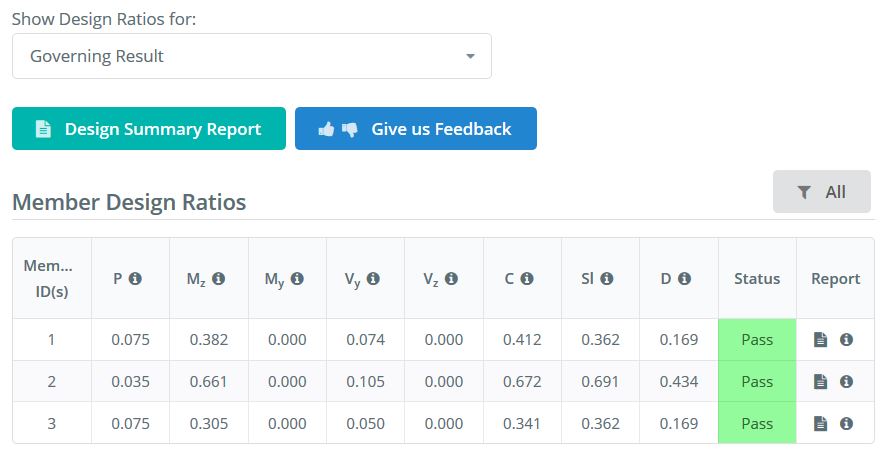
このウィンドウは、ユニティを表示するメインの結果ページです。, または容量比, 各デザインチェックの. ツールチップにカーソルを合わせるのを忘れないでください (“私” 円の中) 各変数が何を表しているのか正確にわからない場合. 3人全員で連合軍限界状態が支配しているのがわかります.
の デザイン サマリ レポート に似ています 結果概要 そして 報告する 分析フェーズ用, メンバーが経験している力と、定員に達したかどうかを簡潔に把握できます。.
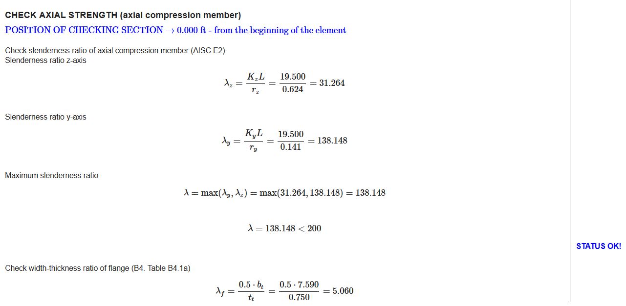
SkyCiv デザイン モジュールの最も排他的な機能の 1 つは、各メンバーの [レポート] 列の下にあるレポート アイコンの 1 つをクリックして利用できる個々のメンバー デザイン レポートです。; これはPDFまたはHTMLに印刷できます. これらのレポートは、メンバーに対して行われているチェックのより詳細な手計算を提供します。. 例えば, ビームの一部を見てみましょう (メンバー 2):
軸力チェックの開始
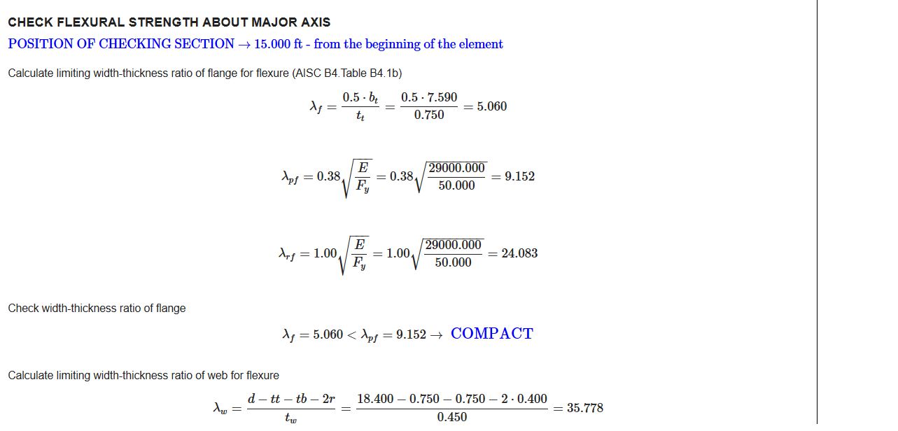
曲げ強度チェックの開始
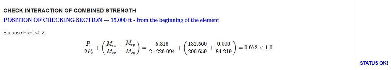
私たちの管理制限状態チェック:
モデリングウィンドウを見ると, フレームには各メンバーのデザイン比率と色分けが表示されていることがわかります. メンバー3人だから “合格した”, これが現在のフレームの外観です:
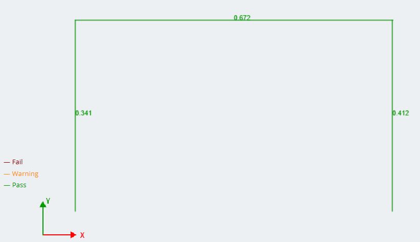
注意: 限界状態の設計比率をモデル空間に表示できます. 各メンバーの管理ケースにデフォルト設定され、どのメンバーが改訂を必要とするかについてユーザーに可能な限り最良のイメージを提供します.
メンバーデザインモジュールの詳細については、モジュールがサポートするコードバージョンを参照してください, 私たちを参照してください ソフトウェアのドキュメント.
次は何ですか?
SkyCivは常に更新され、プラットフォームに機能が追加されています, ほぼ毎日、ソフトウェアの更新が行われる 2 数週間! 他のほとんどの構造工学ソフトウェアは、年に1回だけ更新されます。. この記事の時点で現在開発中の主要な設計更新には、次のものがあります。:
- オプティマイザ: ユーザー向けに部材設計を自動的に最適化する Structural 3D との統合ツール, 設定またはカスタマイズ可能な基準に基づく.
- 風力/雪荷重モジュールから素早く簡単に荷重をかける
- より多くの設計コードとモジュール
- 他の機能が必要? 今すぐ [email protected] でリクエストしてください
SkyCiv接続設計: モーメント接続の設計
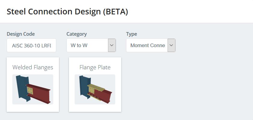
次に、フレームの 2 つの梁と柱の接続の設計を見てみましょう。. 接続位置にモーメントが存在するため、どちらもモーメント接続として設計されます。. であることを確認してください。 封筒絶対最大 接続モジュールは、モジュールに入ったときに表示される力をもたらすため、ワークフローの分析部分に表示されます。. メンバーデザインに似ている, 接続モジュールに入る, クリックしてください 設計 ボタンと モジュールの変更 ドロップダウンメニューで. を押して接続を追加します 接続アセンブリを追加. 切り替え モーメント接続 溶接フランジモーメント接続タイプを見つけます. 接続選択ウィンドウは次のようになります。:
選択した接続タイプで, 接続の親メンバーと子メンバーを識別する必要があります. 設計を簡素化するために、両方の梁の端に同じ接続を使用します。. 分析を振り返ってみると, 右側の接続では、モーメントの大きさが大きくなっていることがわかります, この接続用に設計します. この場合, 右側の列が親メンバーになります (メンバー 1), ビームは子メンバーになります (メンバー 2). これが正しい入力領域で編集されたら, モデル空間は接続を識別し、次のようになります:
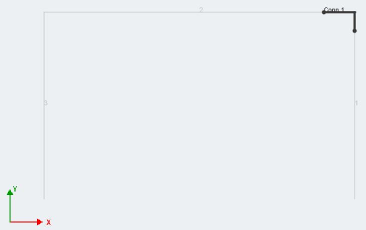
これにより、ユーザーは特定の接続位置を視覚的に表現して確認できます。(s) 彼らは彼らの構造のために設計しています. デザインに入るには, 入力タブの鉛筆の画像をクリックします. 注意, 入力が変更されている間、接続を 3D でレンダリングすることができます。. 接続に変更があるたびに, クリックしてください レンダリングする レンダリング イメージを更新するボタン. フォース カスタマイズ可能, しかし、S3D との接続モジュールの統合のおかげで, それらは自動的に入力されます. 前述のとおり, リストされた力は、S3D の解析部分で表示されていた荷重の組み合わせ/エンベロープから取得されます。.
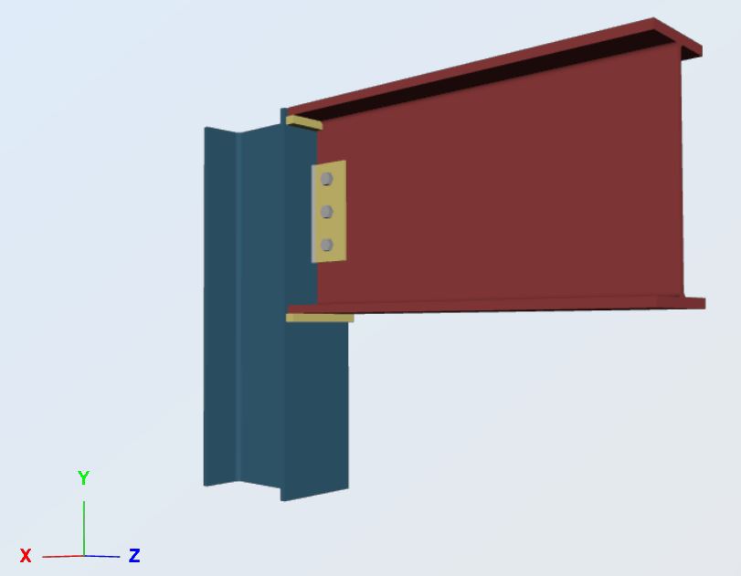
の 繋がり 入力タブは、編集の大部分が行われる場所です. 親会員 そして 子会員 1 S3Dに入力されたメンバー情報から直接情報が引き出されるため、正確である必要があります. これらの領域に関連する設計値を常に確認してください。. 各タブを確認し、希望の角度寸法とボルト エッジ距離を入力します, 溶接サイズと同様に. A36 PL1/4x4x0 を使用します′-9″ と (3)-3/4″ グループ A ボルト. すみ肉溶接サイズの場合, 1/4から始めます″. 必要なすべての情報を関連するフィールドに入力します, 次に、レンダリングを押します. 3D 接続イメージが変更され、最新の情報に更新されます。. これが私たちの例です:
クリック 実行設計. 接続の各部分の結果が左側に表示されます. 部材設計モジュールに類似, 制限状態は色分けされており、接続設計が容量を下回っているか超えているかをユーザーに知らせます. 私たちにとって幸いなことに, 当社が製造したコネクションは各デザイン チェックに合格しており、当社のフレームで機能します。!
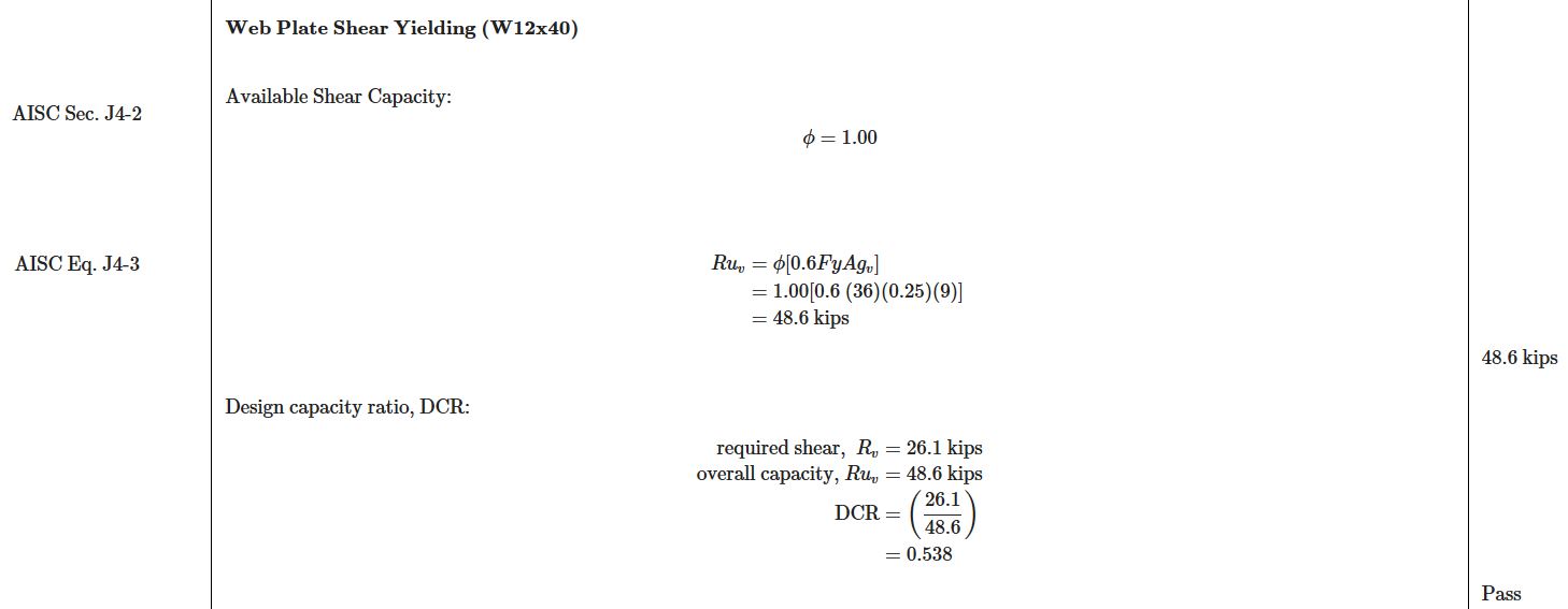
透明性と正確性をテーマに, SkyCiv Connection は、AISC に従って、各スチール接続のフルハンド計算を印刷する力を持っています 360-10 第 J 章. 手計算で示される限界状態は、各設計が実行された後に結果に要約されます. 継続のために, この接続レポートのスニペットをいくつか見てみましょう:
溶接フランジの引張降伏 (AISC 秒. J4)
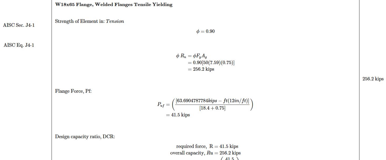
デッドロードからの反応 (AISC 秒. J4):
最後に, 接続モジュールで操作する場合, 接続を図面形式でエクスポートできることに注意してください, または AutoCAD に直接. 詳細をゼロから下書きするのにかかる時間を考慮する, このエクスポート機能は、構造エンジニアの時間を節約しただけではありません, 構造設計者も.
接続モジュールまたはモーメント接続全般に関する詳細情報, 私たちを参照してください ソフトウェアのドキュメント.
次は何ですか?
SkyCivは常に更新され、プラットフォームに機能が追加されています, ほぼ毎日、ソフトウェアの更新が行われる 2 数週間! 他のほとんどの構造工学ソフトウェアは、年に1回だけ更新されます。. この記事の時点で現在開発中の主要な設計更新には、次のものがあります。:
- ベースプレートとアンカーのデザイン: S3D で柱の基部にあるベースプレートとアンカーを分析および設計する
- その他の設計コード (ユーロコードは近日公開予定)
- ユーザー ワークフローを簡素化および高速化するための UI の改善
- 基礎デザイン: 柱の分離基礎と結合基礎および杭を設計する, Structural 3D で 3D モデルと直接統合
最終的な考え
シンプルな 2D モーメント フレームの設計を構想から進めることができました。, 接続設計から詳細まで. このプロセス全体を通して、プログラムを終了したり、複数のモジュールを個別にロードしたりする必要はありませんでした. 各モジュールは、利用可能な他の構造工学ソフトウェアとは異なり、互いにシームレスにつながります. その間ずっと, あなたは任意のブラウザを介して操作しています, 任意のデバイスで, すべてのファイルがクラウドに保存されている. SkyCivスイートで可能な限り機能を拡張!
参考文献
- 構造用鋼製建物の仕様. American Institute of Steel Construction, 2010.
- エリングウッド, ブルース. 「鋼構造物の有用性ガイドライン」。 www.aisc.org, 1989, www.aisc.org/globalassets/aisc/awards/tr-higgins/past-winners/serviceability-guidelines-for-steel-structures.pdf.