ASに準拠した単杭設計 2159 (2009) & 3600 (2018)
横荷重が大きい場合や土壌条件が悪い場合, 杭基礎は浅い基礎よりも好ましい. 杭を回避するために、土壌改良方法などの試みを行うことができます, しかしながら, これらの方法には高価なプロセスが含まれる可能性があります, ここでこの場合, 山はおそらくさらに安い.
SkyCiv Foundation Design モジュールには、American Concrete Institute に準拠した杭の設計が含まれています (ACI 318) およびオーストラリアの基準 (なので 2159 & 3600).
SkyCivの 詳細な計算レポートをエクスポートして、成果物または計算パッケージとして使用します ASの適用が簡単になります 2159 そして 3600 構造プロジェクトのチェックイン.
SkyCivのFoundationDesignソフトウェアを試してみたい? 私たちの無料ツールを使用すると、ユーザーはダウンロードやインストールなしで耐荷重計算を実行できます!
杭の地盤強度の設計
杭にかかる垂直荷重は、杭の端部耐力とその長さに沿った外皮またはシャフトの摩擦によって支えられます。. 設計地盤強度 (Rd,g) 究極の地盤工学的強度に等しい (Rd,と) 地盤工学的削減係数を掛けたもの (øg) に指定されているように なので 2159 セクション 4.3.1.
\({R}_{d,g} = {ø}_{g} × {R}_{d,と}\) (1)
Rd,g = 地盤強度の設計
Rd,と = 究極の地盤工学的強度
øg = 地盤工学的削減係数
究極の地盤強度 (Rd,と)
最終的な地盤工学的強度は、杭の因数分解された表皮摩擦の合計に等しい (fメートル,s ) 側表面積×基礎抵抗×杭先端断面積×.
\( {R}_{d,と} = [{R}_{s} × ({f}_{メートル,s} × {あ}_{s} )] + ({f}_{b} × {あ}_{b} )\) (2)
Rs = シャフト抵抗の低減係数
fメートル,s = シャフトとの摩擦抵抗
あs = 横表面積
fb = ベース抵抗項
あb = 杭先端の断面積
より詳細なガイドについて, 計算に関する記事をご覧ください 皮膚摩擦抵抗とエンドベアリング能力.
地盤工学的削減係数 (øg)
地盤工学的低減係数は、さまざまな要因を考慮した最終設計のためのリスクベースの計算です。, サイトの状態など, パイルデザイン, および設置要因. その値の範囲は、一般的に 0.40 に 0.90. なので 2159 4.3.1 また、式に示すようにその値を推定する方法についても述べています (3).
\( {ø}_{g} = {ø}_{GB} + [K× ({ø}_{tf} – {ø}_{GB})] ≥ {ø}_{GB} \) (3)
øGB = 基本的な地盤強度低下係数
øtf = 固有のテスト要素
K= テストの利点係数
固有の試験と試験の利点係数は両方とも、杭に使用される荷重試験の種類に依存します。. それらの値は表に指定されています 1 そして方程式について (4) そして (5). 杭荷重試験についてはセクションで簡単に説明します。 8 ASの 2159.
| 固有のテスト要素 (øtf) | |||||||||||||
|---|---|---|---|---|---|---|---|---|---|---|---|---|---|
| 静荷重試験 | 0.90 | ||||||||||||
| 迅速な負荷テスト | 0.75 | ||||||||||||
| 既成杭の動的荷重試験 | 0.80 | ||||||||||||
| 既成杭以外の動的荷重試験 | 0.75 | ||||||||||||
| 双方向負荷テスト | 0.85 | ||||||||||||
| テストなし | 0.80 | ||||||||||||
テーブル 1: 固有のテスト係数値
静荷重試験の試験利点係数:
\( K = frac{1.33 ×p}{p + 3.3} ≤ 1\) (4)
動的負荷テストのテスト利点係数:
\( K = frac{1.13 ×p}{p + 3.3} ≤ 1\) (5)
p = テストされ、合格基準を満たした杭の合計の割合
基本的な地盤強度低下係数は、セクションで説明するリスク評価手順を使用して評価されます。 4.3. ASの 2159. 上記手順の結果が個人のリスク評価です (内部利益率) および全体的な設計 平均リスク評価 (到着) ø の値を決定するために使用されます。GB 表に示すように 2.
| 基礎地盤強度低下係数 (øGB) | |||||||||||||
|---|---|---|---|---|---|---|---|---|---|---|---|---|---|
| 平均リスク評価 (到着) | リスクカテゴリー | øGB 冗長性の低いシステムの場合 | øGB 高冗長システム向け | ||||||||||
| ARR ≤ 1.5 | とても低い | 0.67 | 0.76 | ||||||||||
| 1.5 < ARR ≤ 2.0 | 非常に低いから低い | 0.61 | 0.70 | ||||||||||
| 2.0 < ARR ≤ 2.5 | 低 | 0.56 | 0.64 | ||||||||||
| 2.5 < ARR ≤ 3.0 | 低から中程度 | 0.52 | 0.60 | ||||||||||
| 3.0 < ARR ≤ 3.5 | 中程度 | 0.48 | 0.56 | ||||||||||
| 3.5 < ARR ≤ 4.0 | 中程度から高程度 | 0.45 | 0.53 | ||||||||||
| 4.0 < ARR ≤ 4.5 | 高い | 0.42 | 0.50 | ||||||||||
| 到着 > 4.5 | すごく高い | 0.40 | 0.47 | ||||||||||
テーブル 2: 基本的な地盤工学的低減係数の値, (なので 2159 テーブル 4.3.2)
低冗長性システムは重負荷の単一杭であり、高冗長性システムには大きな杭キャップの下にある大規模な杭グループまたは 2 つ以上の杭グループが含まれます。 4 杭.
構造強度の設計
杭は柱とほぼ同じ構造設計. 設計強度 (Rd,s) 究極の能力が必要, 軸力やせん断力など, と曲げモーメント. コンクリート杭の設計構造強度は、設計極限強度に相当します。 (R我ら) 強度減少係数で減少 (øs) および具体的な配置係数 (k), セクションで述べたように 5.2.1 ASの 2159.
\( {R}_{d,s} = {ø}_{s} × k × {R}_{我ら} \) (6)
øs = 強度低下係数
k = コンクリート打設係数
R我ら = 究極の設計強度
強度低下係数の値を表に示します。 3. コンクリート配置係数の範囲は 0.75 に 1.0, 杭工法による. しかしながら, コンクリート、グラウト以外の杭用, k は 1.0.
| 強度低下係数 (ø) | |||||||||||||
|---|---|---|---|---|---|---|---|---|---|---|---|---|---|
| 曲げのない軸力 | 0.65 | ||||||||||||
| 軸力なしで曲げる (øポンド) | 0.65 ≤ 1.24 – [(13 ×k=最も近いサポートの面までのせん断が考慮されているセクションの距離)/12] ≤ 0.85 | ||||||||||||
| 軸圧縮による曲げ: | |||||||||||||
| (私) Nあなた ≧Nウブ | 0.60 | ||||||||||||
| (ii) Nあなた < Nウブ | 0.60 + {(øポンド – 0.66) × [1 – (Nあなた/Nウブ)]} | ||||||||||||
| 剪断 | 0.70 | ||||||||||||
テーブル 3: 強度低下要因 (テーブル 2.2.2, なので 3600-18)
単一杭の軸方向および曲げ能力
コラムに似ている, パイルは、圧縮と曲げの複合荷重を受けることもあります。. 軸方向および曲げ能力は、相互作用図を使用してチェックされます. この図は、純粋な曲げ点からバランス点に達するまでの荷重の増加によって引き起こされる曲げおよび軸方向の容量の挙動を視覚的に表したものです。.
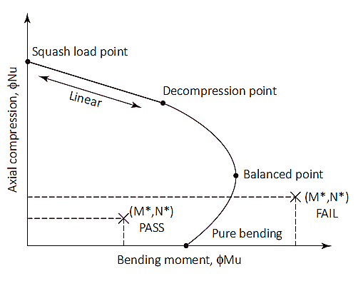
図 1: 列の相互作用図
スカッシュロード (N=最も近いサポートの面までのせん断が考慮されているセクションの距離)
スカッシュ荷重点は、杭が純粋な圧縮で破壊される図上の点です。. この時点で, 曲げずに圧縮状態を維持するために、軸方向の荷重が断面のプラスチックの重心に適用されます。. スカッシュロード (N=最も近いサポートの面までのせん断が考慮されているセクションの距離) そしてプラスチックの重心の位置 (dq) 式に示すように計算されます (7) & (8). プラスチックの重心の位置は次のように解釈できますが、 1/2 対称的な補強レイアウトを備えた対称断面の断面の合計深さの.
\( {ϕN}_{=最も近いサポートの面までのせん断が考慮されているセクションの距離} =ø× [({あ}_{g} – {あ}_{s}) × ({a}_{1} ×f’c) + ({あ}_{s} × {f}_{彼の})] \) (7)
あg = 総断面積
あs = 鋼の総面積
a1 = 1.0 – (0.003 ×f’c) [0.72 ≦α1 ≤0.85]
f’c = コンクリート強度
f彼の = 鋼の降伏強さ
\( {d}_{q} = frac{[(b×D) – {あ}_{s}] × ({a}_{1} ×f’c) × 合計_{i=1}^{ん} ({あ}_{バイ} × {f}_{彼の} × {d}_{する})}{{N}_{=最も近いサポートの面までのせん断が考慮されているセクションの距離}} \) (8)
b = パイル断面幅
D = 杭断面の深さまたは直径
あバイ = 検討中の鉄筋の面積
dする = 検討中の鉄筋の深さ
荷重点から減圧点までを押しつぶす
減圧点とは、極度に圧縮された繊維におけるコンクリートのひずみが次の値に等しい場所です。 0.003 極限引張繊維のひずみはゼロです. 圧壊荷重と減圧点の間の杭の強度は、強度低下係数を使用して線形補間によって計算できます。 (øs) の 0.6.
減圧点から純粋な曲げまで
純粋な曲げ点は、軸方向の耐荷重がゼロになる場所です。. 減圧点から純粋な曲げへの移行には、強度低下係数が使用されます。 0.6 に 0.8 と入力パラメータ (kあなた) 紹介されています. kの値あなた から始まります 1 減圧点で増加し、純粋な曲げに達するまで減少します。. 2 つの点の遷移の間, バランスの取れた状態が達成されます. この時点で, コンクリートのひずみは限界にあります (ec= 0.003) 外側の鋼のひずみが降伏に達する (es= 0.0025), kの値あなた この時点でおよそ 0.54 強度低下係数は 0.6.
k の値が 1 回になるとあなた 選択されています, 断面の引張力と圧縮力を計算できます. 断面にかかる軸方向荷重は、引張力と圧縮力の合計に相当します。, 一方、曲げモーメントは、中立軸を中心とするこれらの力を分解することによって計算されます。. 圧縮力と引張力の計算を以下に列挙します。
コンクリートによる力 (Fcc):
\( {F}_{cc} = {a}_{2} × ふーん × {あ}_{c} \) (9)
a2 = 0.85 – (0.0015 ×f’c) [a2 ≥0.67]
あc = 圧縮ブロック領域 (図を参照 2)
= b × c × kあなた ×d (長方形の断面)
=(1/2) × (θ – sinθ) × (D/2)2 (円形断面)
γ = 0.97 – (0.0025 ×f’c) [c ≥0.67]
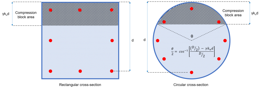
図 2: コンクリート圧縮ブロックエリア
力 (Fそして) と瞬間 (M私) 各バーの貢献:
セクションの各鉄筋は、圧縮または引張のいずれかの力を及ぼします。, バーのひずみ値に応じて (eそして) 式で示される (10).
\( {e}_{そして} = frac{{e}_{c}}{({k}_{あなた} ×d)} × [({k}_{あなた} ×d) – {d}_{する}] \) (10)
dする = 考慮されているバーまでの深さ
ec= コンクリートひずみ = 0.003
もし eそして < 0 (バーが緊張している)
もし eそして > 0 (バーは圧縮中です)
圧縮バー:
\( {F}_{そして} = {σ}_{そして} × {あ}_{バイ} \) (11)
σそして = バーの応力 = 最小 [(eそして × Es ), f彼の]
Es = 鋼の弾性率
あバイ = バーエリア
緊張したバー:
\( {F}_{そして} = [{σ}_{そして} – ({a}_{2} ×f’c)] × {あ}_{バイ} ≥ 0\) (12)
σそして = バーの応力 = 最小 [(eそして × Es ), –f彼の]
Es = 鋼の弾性率
あバイ = バーエリア
各小節ごとの瞬間:
\( {M}_{私} = {F}_{そして} × {d}_{する} \) (13)
杭の軸方向能力:
\( {島}_{あなた} =ø× [ {F}_{cc} + {Σ}_{i=1}^{ん} {F}_{そして}]\) (14)
杭の曲げ耐力:
\( {痛い}_{あなた} =ø× [ ({N}_{あなた} × {d}_{q}) – ({F}_{cc} × {そして}_{c}) – {Σ}_{i=1}^{ん} {M}_{私}] \) (15)
設計曲げモーメント:
セクション 7.2 杭の水平方向の位置決めには、杭の位置ずれ許容値が 75 mm である必要があることを指定します。. この要件により、アキシアル荷重に 75mm の偏心量を乗じたものに等しい曲げモーメントが発生する可能性があります。. さらに, 軸力に次の値を乗じたものに等しい最小設計モーメントも考慮する必要があります。 5% パイルの全体の最小幅の. したがって, 設計曲げモーメントは、式 16a と式 16b の間の大きい方の値である必要があります。.
\( {M}_{d} = {{M}^{*}}_{適用} + ({N}^{*} × 0.075 メートル) \) (16a)
\( {M}_{d} = {N}^{*} × (0.05 ×D) \) (16b)
Md = 設計曲げモーメント
ま*適用 = 適用モーメント
N* = アキシアル荷重
D = パイル幅
単一杭のせん断耐力
せん断強度の計算は、セクションに従って行うものとします。 8.2 ASの 3600. せん断強度は、コンクリートと鉄筋のせん断耐力を合わせたものと同等です。 (方程式 17).
\( {øV}_{あなた} =ø× ({V }_{SkyCiv Foundationには、オーストラリア規格に準拠した孤立した基礎の設計が含まれています¹} + {V }_{我ら}) ≤ {øV}_{あなた,最高} \) (17)
コンクリートのせん断強度 (V SkyCiv Foundationには、オーストラリア規格に準拠した孤立した基礎の設計が含まれています¹)
せん断耐力へのコンクリートの寄与は、式に示すように計算されます (18) セクションで定義されています 8.2.4.1 ASの 3600. このセクションでは、√f’c の値が次を超えないことも必要です。 9.0 MPa. パラメータ k の値v そして θv セクションで提案されている簡略化された方法を使用して決定されます。 8.2.4.3 ASの 3600.
\( {V }_{SkyCiv Foundationには、オーストラリア規格に準拠した孤立した基礎の設計が含まれています¹} = {k}_{v} × b × {d}_{v} [object Window]{f’c} \) (18)
dv = 有効せん断深さ = 最大 [(0.72 ×D ), (0.90 ×d )]
せん断補強の最小面積の決定 (あsv.min) & kv:
せん断補強の面積 (あSV) 適用された荷重の同じ方向に結ばれた付属のすべての鋼棒の合計棒面積です。. セクション 8.2.1.7 ASの 3600 最小横せん断補強材の式を提供, これは:
\( \フラク{{あ}_{sv.min}}{s} = frac{0.08 [object Window]{f’c} ×b}{{f}_{そしてf}} \)
fそしてf = せん断鉄筋の降伏強度
s= せん断鉄筋の中心間距離
ために (あSV/s) < (あsv.min/s):
\( {k}_{v} = frac{200}{[1000 + (1.3 × {d}_{v} )]} ≤ 0.10\)
ために (あSV/s) ≥ (あsv.min/s):
\( {k}_{v} = 0.15 \)
棒鋼のせん断強度 (V 我ら)
計算されたせん断耐力に対する横せん断鉄筋の寄与は、次の式で示されます。 (19), これはセクションで定義されています 8.2.5 ASの 3600.
\( {V }_{我ら} = frac{{あ}_{SV} × {f}_{そしてf} × {d}_{v}}{s} × ベビーベッド{θ}_{v} \) (19)
θv= 圧縮ストラットの傾斜角 = 36°
最大せん断強度 (V u.max)
せん断能力は制限されており、いかなる場合もセクションに指定されている最大値を超えてはなりません 8.2.6 ASの 3600 (方程式 20).
\( {V }_{u.max} = 0.55 × [ (f'c × b × {d}_{v}) [object Window]{ベビーベッド{θ}_{v} + ベビーベッド{a}_{v}}{1 + ベビーベッド^{2}{θ}_{v} }] \) (20)
av= 傾斜せん断鉄筋と縦方向引張鉄筋間の角度≈ 90°
極限せん断強度 (V あなた)
コンクリートとせん断補強材によって寄与される合計せん断強度は、V の制限値以下でなければなりません。u.max
\( {V }_{あなた} = ({V }_{SkyCiv Foundationには、オーストラリア規格に準拠した孤立した基礎の設計が含まれています¹} + {V }_{我ら} ) ≤ {V }_{u.max} \) (21)
設計せん断強度 (øVあなた)
極限せん断強度に適用される容量減少係数は、 ø = 0.7. したがって, 杭の設計せん断強度は次の式で与えられます。:
\( {øV}_{あなた} =ø× ({V }_{SkyCiv Foundationには、オーストラリア規格に準拠した孤立した基礎の設計が含まれています¹} + {V }_{我ら} ) \) (22)
参考文献
- パック, ロニー (2018). 構造エンジニアのためのオーストラリアのガイドブック. CRCプレス.
- 杭の設計と施工 (2009). なので 2159. オーストラリア規格
- コンクリート構造物 (2018). なので 3600. オーストラリア規格