SkyCiv Structural 3D での曲線およびスパイラル部材のモデリング
曲線部材
SkyCiv は、モデリング ワークフローを高速化するための高度な操作を多数提供します。.
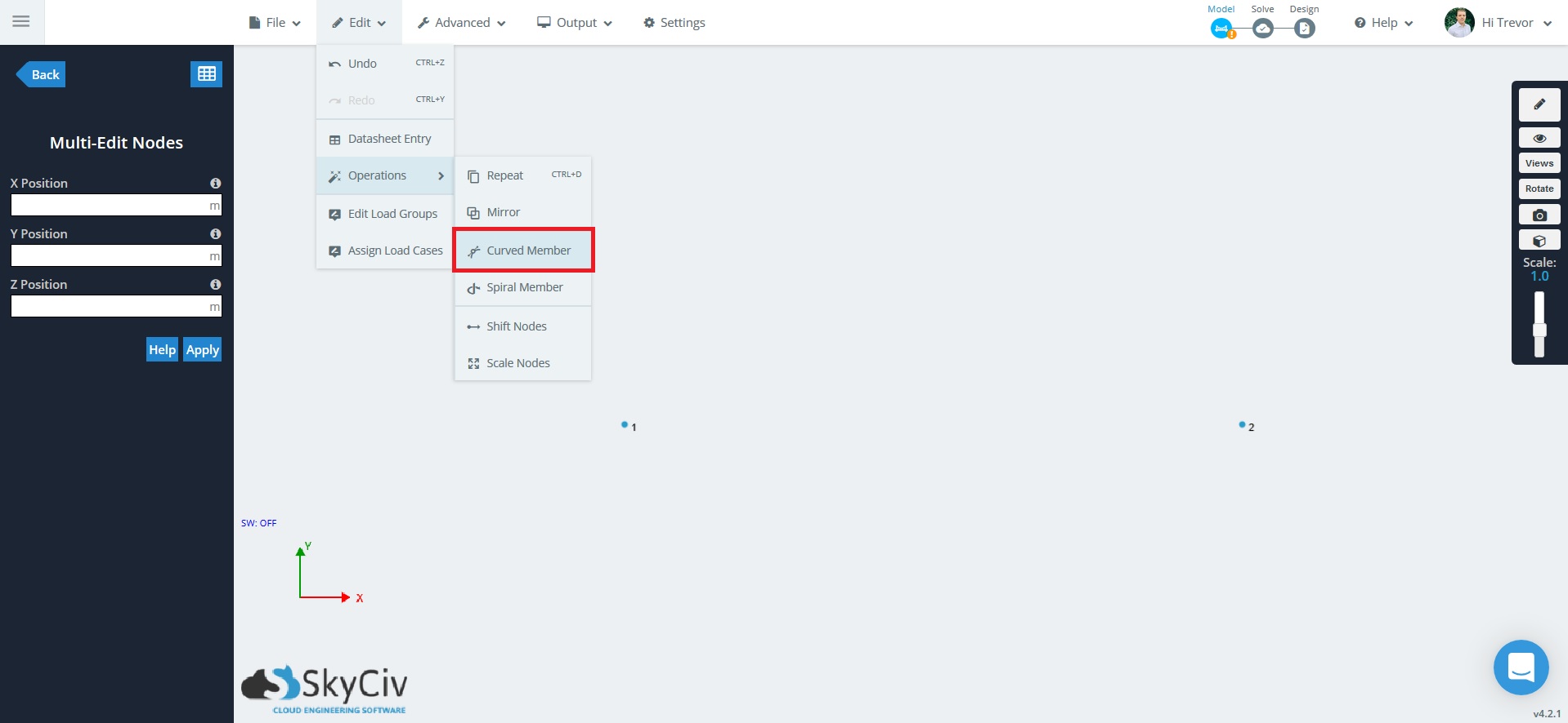
「曲がったメンバー」’ 操作により選択できるようになります (2) ノードとアークを生成する (メンバーで構成された) それらの間の. この機能は、湾曲した梁やアーチなどの湾曲した構造をモデル化する場合に便利です.
例: 湾曲したビームのモデリング
この例では, 曲がった梁をモデル化します. 最初のステップは 2 つのノードを作成することです. 座標を使用する (0,0,0) そして (10,0,0) つまり、2 つのノードは次のように区切られています。 10 x 方向のフィート.


- 会員数 – 曲率を作成するために使用されるメンバーの数.
- メンバーのセクションID – 各メンバーに適用される断面ID.
- 半径 – 2 つのノード間の曲線の半径. 半径の最小値はノード間の距離の半分です
- 飛行機 – 曲線が生成される座標平面.
- 方向 – ポジティブまたはネガティブ, カーブの方向に影響します “旅行する”
例えば, 我々は使用するだろう 20 曲線を構成するメンバー (メンバーが多ければ多いほど, 曲線がより正確に表現され、その逆も同様です。). 半径については, 最小値は 2 つのノード間の距離の半分です. この例の 2 つのノードは次のように区切られているため、 10 フィート, 最小の半分の距離は 5 フィート. 半径の最小値よりも大きい値を指定すると、「より平坦な」結果になります。’ 曲線. カーブのメンバーのセクション ID を直接指定して、特定の断面を割り当てることもできます。. 平面オプション (XY平面, XZ平面) そして方向 (ポジティブ, ネガティブ) 指定することもできます.


スパイラルメンバー
「スパイラル メンバー」操作では、開始点として 1 つのノードを選択できます, そしてスパイラルを生み出す (メンバーで構成された). この機能は、ある種の階段や手すりなどの螺旋構造をモデル化するときに役立ちます。.
例: スパイラル構造のモデリング
この例では, スパイラル構造をモデル化します. 最初のステップは原点にあるノードです (0,0,0).

ノードをクリックして選択します. 選択時, ノードが青に変わります.

上部のツールバーに移動します, その後 編集する > 操作 > スパイラルメンバー.
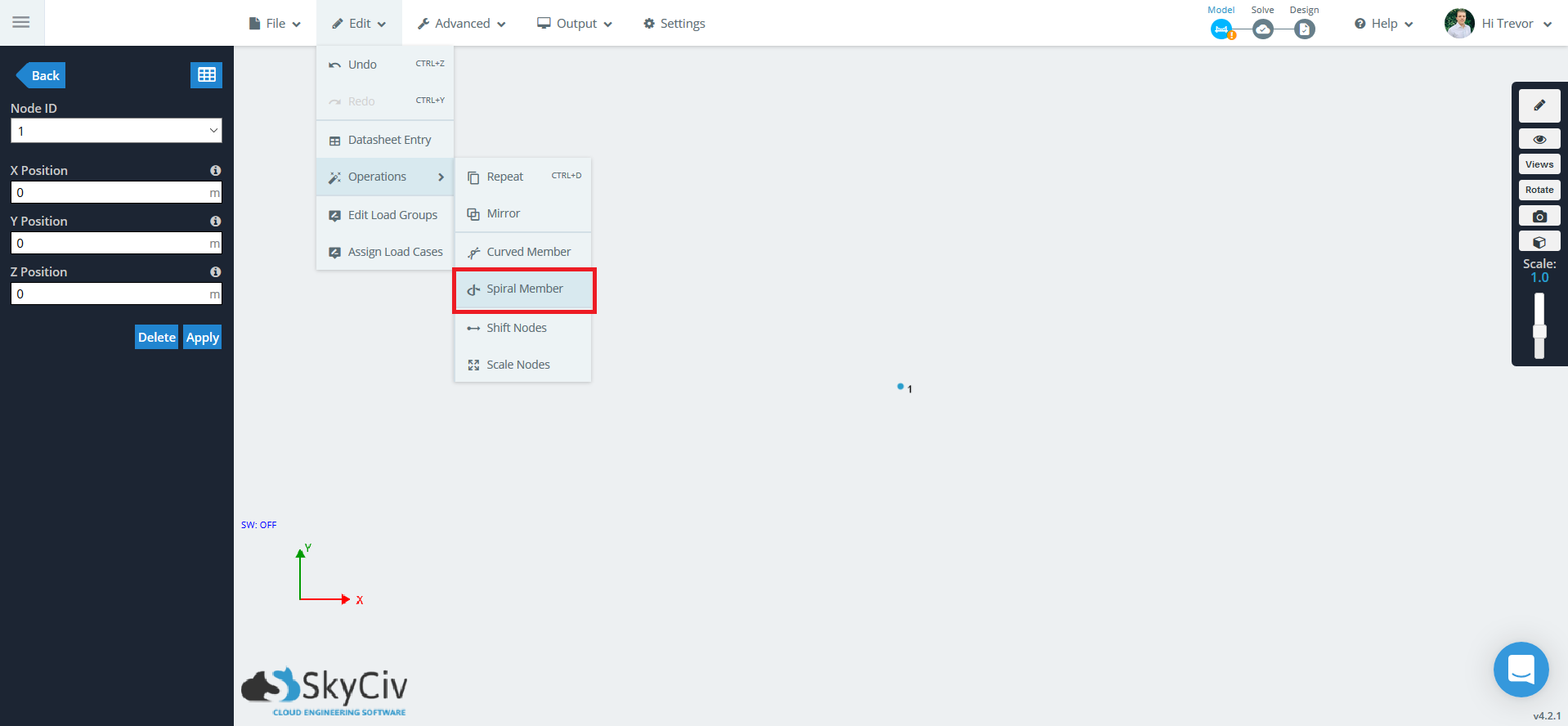
ポップアップが表示され、いくつかのオプションが表示されます.
- 利用するメンバーの合計数 – スパイラル構造を構成するメンバーの数.
- メンバーのセクションID – 各メンバーに適用される断面ID.
- らせん基点中心点 – らせん構造の中心. ×を入力してください, そして, z 座標.
- らせんの長さ – ターン間の長さ, 伝播方向に.
- の数 360 度ターン – 完全なターン数.
- 方向 – 螺旋の伝播方向.
- 回転方向 – 螺旋が曲がる方向 (時計回りに / 反時計回り) 特定の方向に伝播するため.

生成されたスパイラル構造を以下に示します.

テストテスト