この記事では、2 つの鉄筋コンクリート スラブの設計例について説明します。, 一方向および二方向曲げを含む. 主な目標は、手計算とSkyCivプレート設計モジュールの間で得られた結果を比較することです. ユーロコードを使用します 2 鉄筋コンクリート構造用.
スラブの典型的なケースを定義する場合、建築基準法にも同様のアプローチがあります。. このトピックについてもう少し詳しく知りたい場合, スラブ設計に関する次の記事を読むことをお勧めします ACI スラブの設計例と SkyCiv との比較 そして オーストラリア規格 AS3600 スラブの設計例と SkyCiv との比較
一方向スラブの設計例
分析する最初のケースは小さな 1 階建ての建物です。 (図 1, 図 2) 一方向として記述されたスラブ動作を持っています.
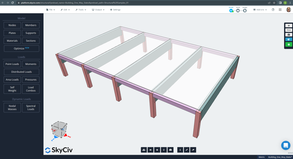
図 1. 小さな建物の一方向スラブの例. (構造3D, SkyCivクラウドエンジニアリング).
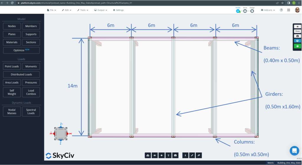
図 2. 小さな建物の一方向スラブの例 (平面寸法). (構造3D, SkyCivクラウドエンジニアリング).
スラブの例, 要約すれば, 材料, 要素のプロパティ, 考慮すべき負荷 :
- スラブタイプ分類: 1 – 方法行動 \(\フラク{L_2}{L_1} > 2 ; \フラク{14メートル}{6メートル}=2.33 > 2.00 \) OK!
- 建物の占有: 住宅用
- スラブの厚さ \(t_{スラブ}=0.25m\)
- 鉄筋コンクリート密度 \(\rho_w = 25 \フラク{kN}{m^3}\)
- でのコンクリートの特性圧縮強度 28 日々 (C25\30) \(fck = 25 MPa \)
- スラブ自重 \(Dead = \rho_w \times t_{スラブ} = 25 \フラク{kN}{m^3} \倍 0.25m = 6.25 \フラク {kN}{m^2}\)
- 重畳死荷重 \(SD = 3.0 \フラク {kN}{m^2}\)
- 活荷重 \(L = 2.0 \フラク {kN}{m^2}\)
EN-2 による手計算
このセクションで, ユーロコード規格の参照を使用して、必要な鉄筋を計算します. 最初に、スラブの単一幅のストリップによって実行される合計の要素曲げモーメントを取得します。.
- 死荷重, \(g = (3.0 + 6.25) \フラク{kN}{m^2} \回 1 m = 9.25 \フラク{kN}{メートル}\)
- 活荷重, \(q = (2.0) \フラク{kN}{m^2} \回 1 m = 2.0 \フラク{kN}{メートル}\)
- 究極の負荷, \(Fd = 1.35\times g + 1.5\回 q = (1.35\回 9.25 + 1.5\回 2.0)\フラク{kN}{メートル} =15.5 \frac{kN}{メートル} \)
鉄筋面積を求める前に, スパン有効深度比を確認する必要があります. 2つの主なケース:
| 構造システム | 基本スパン有効深度比 | ||
|---|---|---|---|
| 構造系係数 K | 高応力コンクリート %(\(\ロー= 1.5 )\) | 軽く応力を加えられたコンクリート %(\(\ロー= 0.5 )\) | |
| 1. 連続ビームまたは一方向連続スラブまたは 1 つの長辺で連続する双方向スラブのエンド スパン | 1.3 | 18 | 26 |
| 2. 連続梁または一方向または双方向のスパンスラブの内部スパン | 1.5 | 20 | 30 |
最も重大なケースは 1 番の場合です, それで, の比率を選択します 26.
- \(t_{分}= frac{L}{知っている}+cover+0.5\dot bar_{直径}= frac{6メートル}{26}+0.025m+0.5\times 12mm=0.26m \) 〜 \(0.25m). 全体の厚みはまだ十分, OK!
今, 一方向連続スラブにテーブルを使用する時が来ました:
| サポート終了条件 | まずはインテリアサポート | 内部スパンの中間 | 内部サポートで | ||||
|---|---|---|---|---|---|---|---|
| ピン留め | 継続的 | ||||||
| アウターサポート | エンドスパンの中間付近 | サポート終了 | エンドスパン | ||||
| 瞬間 | 0 | 0.086フロリダ州 | – | 0.075フロリダ州 | – | 0.063フロリダ州 | – |
| 0.04フロリダ州 | 0.086フロリダ州 | 0.063フロリダ州 | |||||
| 剪断 | 0.4F | – | – | – | |||
| 0.46F | 0.6F | 0.5F | |||||
どこ:
- L は実効スパン
- F は、スパン内の総最終荷重です。 (1.35合同 + 1.5Qk; Gk は死荷重、Qk は活荷重です。, それぞれ)
一例だけ説明します (継続エンドサポート) 残りは次の表に表示されます.
- \(F=Fd\times L = 15.5 \フラク{kN}{メートル} \倍 6m = 93.0 kN \)
- \(M=0.04FL=0.04 \times 93.0 kN \times 6m= -22.32{kN}{メートル}\)
- \(d=230mm \)
- \(K=\frac{M}{{b}{d^2}{f_{ck}}}= frac{22.32\10^6倍 {N}{んん}}{{1000んん}\回{(230 んん)^ 2}\回 {25 \フラク{N}{mm^2}}}=0.016877\)
- \(l_a = 0.95 \)
- \(z=l_a \times d = 0.95\times 230mm = 218.50 mm\)
- \(A_s = frac{M}{{0.87}{f_{yk}}{と}}= frac{22.32\10^6倍 {N}{んん}}{0.87\回 500 {N}{mm^2} \回 {218.50んん} = 234.83 mm^2 }\)
- \(A_{s,分}=0.0013{b}{d}=0.0013\times 1000mm \times 230 mm =299 mm^2\)
- \(A_{st}=最大(として, A_{s,分}) = 最大(234.83, 299) mm^2 = 299 mm^2 \)
| 瞬間 | エクステリア ネガティブ 左 | エクステリアポジティブ | 外側の負の右 | 内側の負の左 | インテリアポジティブ | 内側の負の右 |
|---|---|---|---|---|---|---|
| M値, kN-m | 22.32 | 35.15 | 41.85 | 48.00 | 35.15 | 35.15 |
| K | 0.0168 | 0.0266 | 0.03164 | 0.0362 | 0.0266 | 0.0266 |
| と, んん | 218.50 | 218.50 | 218.50 | 218.50 | 218.50 | 218.50 |
| \(として, mm^2\) | 234.83 | 369.815 | 440.31 | 505.011 | 369.815 | 369.815 |
| \(A_{s,分},mm^2\) | 299.00 | 299.00 | 299.00 | 299.00 | 299.00 | 299.00 |
| \(A_{st} {mm^2}\) | 299.00 | 369.815 | 440.31 | 505.011 | 369.815 | 369.815 |
次の動きは、SkyCiv のプレート設計モジュールを使用して鉄筋鉄筋を計算することです. お願いします, 次のセクションを読み続けてください!.
あなたがSkyCivで初めての場合, サインアップして自分でソフトウェアをテストする!
SkyCiv S3D プレート デザイン モジュールの結果
このセクションでは、鉄筋領域の取得について説明しますが、ソフトウェアを使用するだけです, の プレート設計モジュール. 簡潔に, 結果または重要な情報のみを画像で表示します.
モデルを分析する前に, プレート メッシュ サイズを定義する必要があります. 参考文献 (2) のシェル要素のサイズを推奨します 1/6 短いスパンのまたは 1/8 ロングスパンの, それらの短い方. この値に従う, 我々は持っています \(\フラク{L2}{6}= frac{6メートル}{6} = 1メートル \) または \(\フラク{L1}{8}= frac{14メートル}{8}=1.75m \); 最大推奨サイズとして 1m を採用し、適用メッシュ サイズは 0.50m です。.
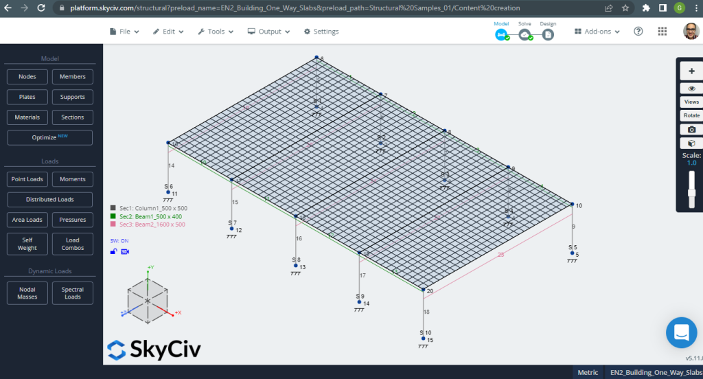
図 3. プレートメッシュ. (構造3D, SkyCivクラウドエンジニアリング).
解析構造モデルを改善したら, 線形弾性解析を実行します. スラブを設計するとき, 垂直変位がコードで許可されている最大値よりも小さいかどうかを確認する必要があります. ユーロコード 2 の最大保守可能垂直変位を確立しました \(\フラク{L}{250}= frac{6000んん}{250}=24.0 mm\).
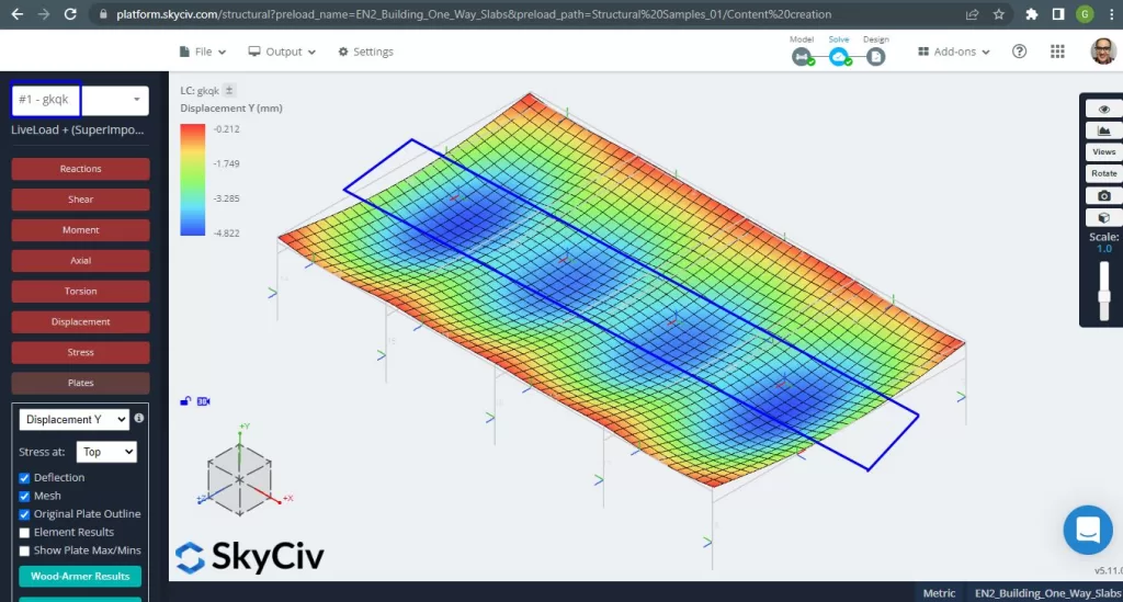
図 4. 垂直変位, スパンの中心での最大値. (構造3D, SkyCivクラウドエンジニアリング).
コード参照値に対する最大垂直変位の比較, スラブの剛性は十分です. \(4.822 んん < 24.00mm\).
スラブのスパンの最大モーメントは、正の場合は中心に、負の場合は外側と内側のサポートにあります。. 次の画像でこれらのモーメントの値を見てみましょう.
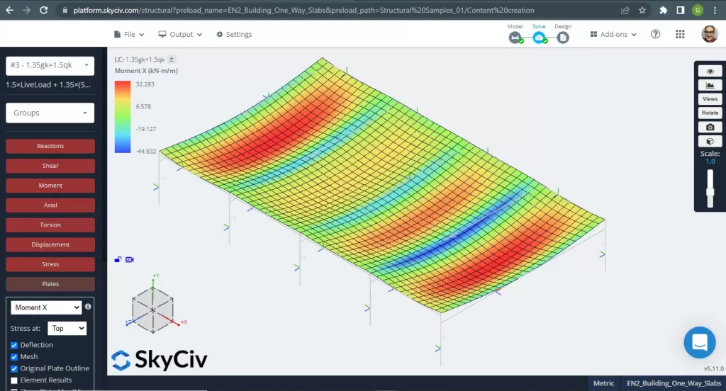
図 5. X 方向の曲げモーメント. (構造3D, SkyCivクラウドエンジニアリング).

図 6. Y方向の曲げモーメント. (構造3D, SkyCivクラウドエンジニアリング).
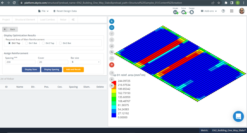
図 7. 上部の X 方向の鉄筋. (構造3D, SkyCivクラウドエンジニアリング).
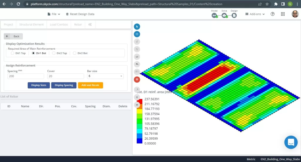
図 8. 下部の X 方向のスチール補強. (構造3D, SkyCivクラウドエンジニアリング).

図 9. 上部の Y 方向の鉄筋. (構造3D, SkyCivクラウドエンジニアリング).
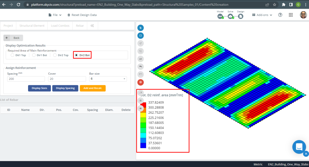
図 10. 下部の Y 方向の鉄筋. (構造3D, SkyCivクラウドエンジニアリング).
結果比較
この一方向スラブ設計例の最後のステップは、S3D 解析によって得られた鉄筋面積を比較することです。 (ローカル軸 “2”) と手計算.
| モーメントと鋼材エリア | エクステリア ネガティブ 左 | エクステリアポジティブ | 外側の負の右 | 内側の負の左 | インテリアポジティブ | 内側の負の右 |
|---|---|---|---|---|---|---|
| \(A_{st, 手計算} {mm^2}\) | 299.00 | 369.82 | 440.31 | 505.011 | 369.82 | 369.82 |
| \(A_{st, S3D} {mm^2}\) | 308.41 | 337.82 | 462.61 | 462.61 | 262.75 | 308.41 |
| \(\デルタ_{差分}\) (%) | 3.051 | 8.653 | 4.820 | 8.400 | 28.95 | 16.610 |
値の結果が互いに非常に近いことがわかります. これは、計算が正しいことを意味します!
あなたがSkyCivで初めての場合, サインアップして自分でソフトウェアをテストする!
双方向スラブの設計例
SkyCiv 3Dプレート設計モジュールは、イメージングできるあらゆるタイプの建物を分析および設計できる強力なソフトウェアです. 2 番目の設計スラブの例, フラットスラブシステムを実行することにしました (図 11).
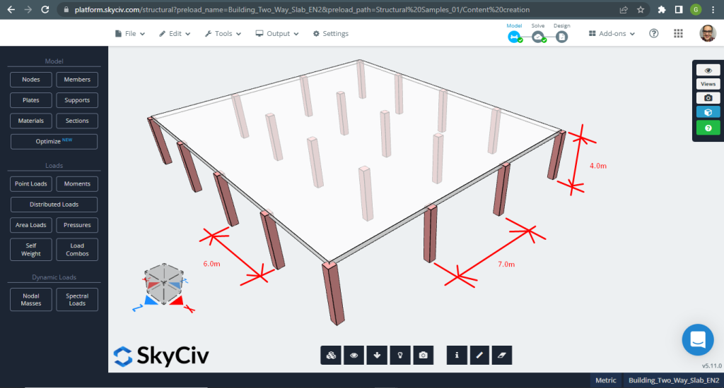
図 11. 小さな建物の一方向スラブの例. (構造3D, SkyCivクラウドエンジニアリング).
スラブの例, 要約すれば, 材料, 要素のプロパティ, 考慮すべき負荷 :
- スラブタイプ分類: 二 – 方法行動 \(\フラク{L_2}{L_1} \インクルード 2 ; \フラク{7メートル}{6メートル}=1.17 \le 2.00 \) OK!
- 建物の占有: 住宅用
- スラブの厚さ \(t_{スラブ}=0.30m\)
- 鉄筋コンクリート密度 \(\rho_w = 25 \フラク{kN}{m^3}\)
- でのコンクリートの特性圧縮強度 28 日々 (C25\30) \(fck = 25 MPa \)
- スラブ自重 \(Dead = \rho_w \times t_{スラブ} = 25 \フラク{kN}{m^3} \倍 0.30m = 7.5 \フラク {kN}{m^2}\)
- 重畳死荷重 \(SD = 3.0 \フラク {kN}{m^2}\)
- 活荷重 \(L = 2.0 \フラク {kN}{m^2}\)
EN-2 による手計算
最初のステップは、総最終負荷を定義することです:
- 死荷重, \(g = (3.0 + 7.5) \フラク{kN}{m^2} \回 7 m = 73.50 \フラク{kN}{メートル}\)
- 活荷重, \(q = (2.0) \フラク{kN}{m^2} \回 7 m = 14.00 \フラク{kN}{メートル}\)
- 究極の負荷, \(Fd = 1.35\times g + 1.5\回 q = (1.35\回 73.50 + 1.5\回 14.00)\フラク{kN}{メートル} =120.225 \frac{kN}{メートル} \)
手計算の場合, 構造は一連の同等のフレームに分割する必要があります. この目標を達成するには、次の方法を使用できます:
- モーメント分布 (ハーディークロス工法) フレーム解析用.
- コンピュータ上でのフレーム解析のための剛性法. 私たちを試してみてください 剛性マトリックス計算機.
- 次の要件に調整された一方向のモーメント係数を使用した簡略化された方法 (分析したモデルが単純であるため、この方法を選択しました。):
- 横方向の安定性は、スラブと柱の接続に依存しません (建物の横荷重は分析しません);
- 考慮されている方向にほぼ等しいスパンのパネルが少なくとも 3 列あります。 (主な両方向に 4 列と 3 列のパネルがあります。);
- ベイのサイズが \(30m^2\) (私たちのモデルエリアは \(42m^2\)
スラブの例で選択された厚さは、下の表に示されている耐火性の最大最小値よりも大きい.
| 標準耐火性 | 最小寸法 (んん) | |
|---|---|---|
| スラブの厚さ, HS | 軸間距離, a | |
| れい 60 | 180 | 15 |
| れい 90 | 200 | 25 |
| れい 120 | 200 | 35 |
| れい 240 | 200 | 50 |
このセクションで, 縦方向と列ストリップの計算のみを作成します (別の方向を自由に計算してください, 横方向, ミドルストリップ用). 数字に深入りする前に, まず、ストリップに分割する必要があります: 真ん中と列. (デザインストリップの詳細について, このSkyCivの記事をチェックしてください: ACI-318 でスラブを設計する).
- 列ストリップ幅: \(6m/4 = 1.50m\)
- 中間ストリップ幅: \(7メートル – 2\times 1.50m = 4.0m\)
EC2 では、次の表に従って各デザイン ストリップにモーメントを割り当てることができます。
| 列ストリップ | ミドルストリップ | |
|---|---|---|
| エッジ列の負のモーメント | 100% しかし、それ以上 \(0.17{なれ}{d^2}{f_{ck}}\) | 0 |
| 内部コラムの負のモーメント | 60-80% | 40-20% |
| スパンの正のモーメント | 50-70% | 50-30% |
分析中の列ストリップのモーメントのパーセンテージを選択しました:
- エッジ列の負のモーメント: 100%.
- 内部コラムの負のモーメント: 80%
- スパンの正のモーメント: 70%
総設計ストリップ モーメントの計算:
| サポート終了条件 | まずはインテリアサポート | 内部スパンの中間 | 内部サポートで | ||||
|---|---|---|---|---|---|---|---|
| ピン留め | 継続的 | ||||||
| アウターサポート | エンドスパンの中間付近 | サポート終了 | エンドスパン | ||||
| 瞬間 | 0 | 0.086フロリダ州 | – | 0.075フロリダ州 | – | 0.063フロリダ州 | – |
| 0.04フロリダ州 | 0.086フロリダ州 | 0.063フロリダ州 | |||||
| 剪断 | 0.4F | – | – | – | |||
| 0.46F | 0.6F | 0.5F | |||||
どこ:
- L は実効スパン
- F は、スパン内の総最終荷重です。 (1.35合同 + 1.5Qk; Gk は死荷重、Qk は活荷重です。, それぞれ)
一例だけ説明します (継続終了サポート) 残りは次の表に表示されます.
- \(F=Fd\times L = 120.225 \フラク{kN}{メートル} \倍 6m = 721.35 kN \)
- \(M=0.04FL=0.04 \times 721.35 kN \times 6m= -173.124 {kN}{メートル}\)
- \(d=280mm \)
- \(K=\frac{M}{{b}{d^2}{f_{ck}}}= frac{173.124\10^6倍 {N}{んん}}{{1500んん}\回{(280 んん)^ 2}\回 {25 \フラク{N}{mm^2}}}=0.012637\)
- \(l_a = 0.95 \)
- \(z=l_a \times d = 0.95\times 280mm = 266.0 mm\)
- \(A_s = frac{M}{{0.87}{f_{yk}}{と}}= frac{173.124\10^6倍 {N}{んん}}{0.87\回 500 {N}{mm^2} \回 {266.0んん} = 214.0523 mm^2 }\)
- \(A_{s,分}=0.0013{b}{d}=0.0013\times 1500mm \times 280 mm =546 mm^2\)
- \(A_{st}=最大(として, A_{s,分}) = 最大(234.83, 546) mm^2 = 299 mm^2 \)
| 瞬間 | エクステリア ネガティブ 左 | エクステリアポジティブ | 外側の負の右 | 内側の負の左 | インテリアポジティブ | 内側の負の右 |
|---|---|---|---|---|---|---|
| M値, kN-m | 173.124 | 191.125 | 260.064 | 298.281 | 191.125 | 218.429 |
| K | 0.05897 | 0.06500 | 0.0884 | 0.101 | 0.06500 | 0.0743 |
| と, んん | 266.00 | 266.00 | 266.00 | 266.00 | 266.00 | 266.00 |
| \(として, mm^2\) | 1498.366 | 1651.761 | 2247.55 | 2577.835 | 1651.761 | 1887.727 |
| \(A_{s,分},mm^2\) | 546.00 | 546.00 | 546.00 | 546.00 | 546.00 | 546.00 |
| \(A_{st} {mm^2}\) | 1498.366 | 1651.761 | 2247.55 | 2577.835 | 1651.761 | 1887.727 |
次の動きは、SkyCiv のプレート設計モジュールを使用して鉄筋鉄筋を計算することです. お願いします, 次のセクションを読み続けてください!
SkyCiv S3D プレート デザイン モジュールの結果
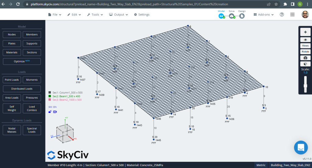
図 12. 小さな建物の一方向スラブの例. (構造3D, SkyCivクラウドエンジニアリング).
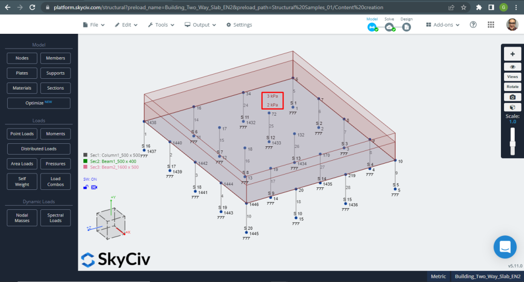
図 13. 小さな建物の一方向スラブの例. (構造3D, SkyCivクラウドエンジニアリング).
スラブを設計するとき, 垂直変位がコードで許可されている最大値よりも小さいかどうかを確認する必要があります. Eurocode は、最大保守可能垂直変位の stablished \(\フラク{L}{250}= frac{6000んん}{250}=24.0 mm\).
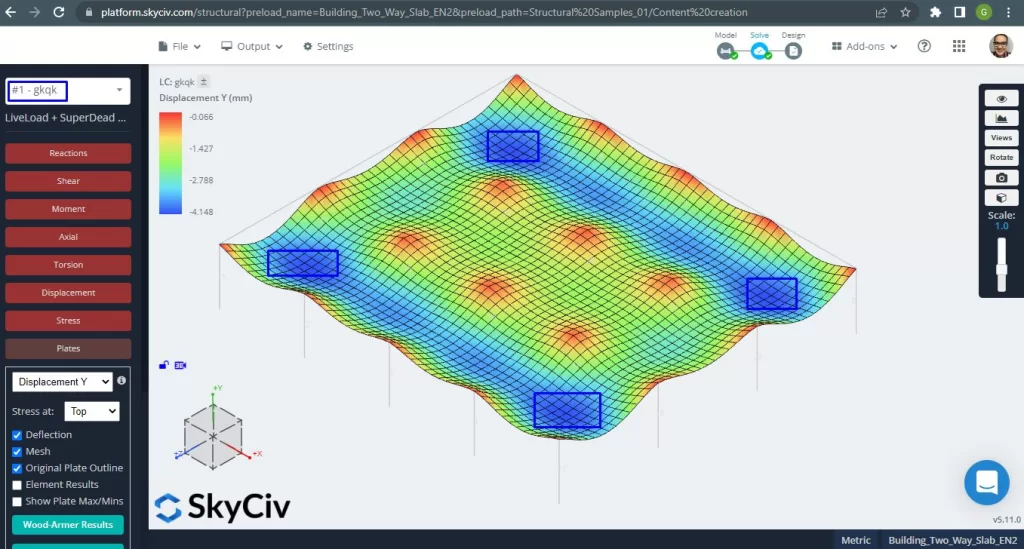
図 14. 小さな建物の一方向スラブの例. (構造3D, SkyCivクラウドエンジニアリング).
上の画像は、垂直方向の変位を示しています. 最大値は -4.148mm で、許容される最大値 -24mm よりも小さいです。. したがって, スラブの剛性は十分です.
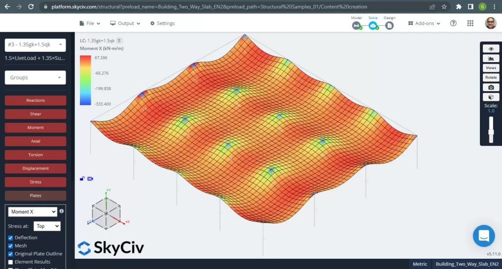
図 15. 小さな建物の一方向スラブの例. (構造3D, SkyCivクラウドエンジニアリング).
画像 15 そして 16 各主方向の曲げモーメントからなる. モーメント分布と値を取る, ソフトウェア, SkyCiv, 次に、鉄筋の総面積を取得できます.

図 16. 小さな建物の一方向スラブの例. (構造3D, SkyCivクラウドエンジニアリング).
鋼補強エリア:
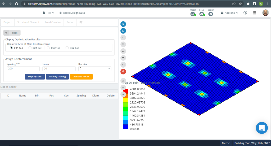
図 17. 小さな建物の一方向スラブの例. (構造3D, SkyCivクラウドエンジニアリング).
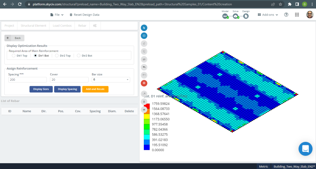
図 18. 小さな建物の一方向スラブの例. (構造3D, SkyCivクラウドエンジニアリング).
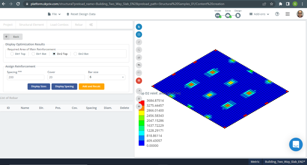
図 19. 小さな建物の一方向スラブの例. (構造3D, SkyCivクラウドエンジニアリング).
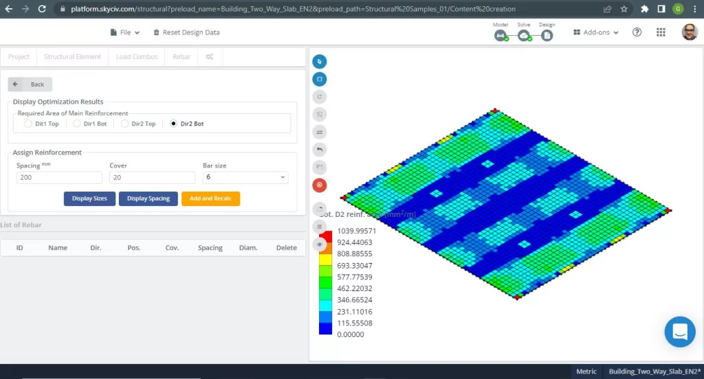
図 20. 小さな建物の一方向スラブの例. (構造3D, SkyCivクラウドエンジニアリング).
結果比較
この双方向スラブ設計例の最後のステップは、S3D 解析と手計算によって得られた鉄筋面積を比較することです。.
X方向の鉄筋と柱帯
| モーメントと鋼材エリア | エクステリア ネガティブ 左 | エクステリアポジティブ | 外側の負の右 | 内側の負の左 | インテリアポジティブ | 内側の負の右 |
|---|---|---|---|---|---|---|
| \(A_{st, 手計算} {mm^2}\) | 1498.366 | 1651.761 | 2247.55 | 2577.835 | 1651.761 | 1887.727 |
| \(A_{st, S3D} {mm^2}\) | 3889.375 | 1040.00 | 4196.145 | 4196.145 | 520.00 | 3175.00 |
| \(\デルタ_{差分}\) (%) | 61.475 | 37.04 | 46.44 | 38.566 | 68.52 | 40.544 |
あなたがSkyCivで初めての場合, サインアップして自分でソフトウェアをテストする!
参考文献
- B. モズレー, R. ハルス, JH. バンジー , “Eurocode 2 に準拠した鉄筋コンクリート設計”, 第七版, パルグレイブ・マクミラン.
- バザン・エンリケ & メリ・ピラーラ, “構造物の耐震設計”, 1ed, クリア.
- ユーロコード 2: コンクリート構造物の設計.