SkyCiv Foundation は、孤立した基礎を簡単にモデル化するための強力なデザインと組み合わせたユーザーフレンドリーなインターフェイスを提供します. 最近リリースされたバージョンでは 3.1, Isolated Foundation のユーザー インターフェイスは次のように分かれています。 2 コンテナ, 左側が入っている 4 を含むタブ 詳細, 財団, 入力 そして 結果, そして、それを含む権利 3Dレンダラー.
私. 詳細
ユーザーがデザインコードを選択したら, ユーザーはプロジェクトの詳細を更新できます。 “詳細” 以下に示すタブ. 単位は選択した設計コードに基づいて自動的に設定されます.
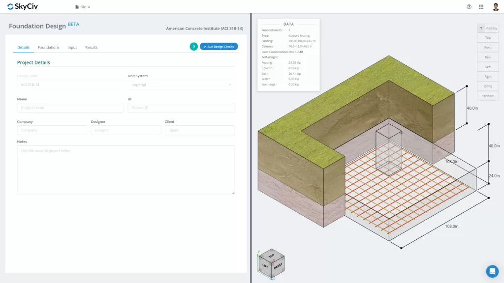
図 1. 「プロジェクトの詳細」タブ
ユーザーはプロジェクトの詳細に関する情報を入力できます, といった
- プロジェクト名
- プロジェクトID
- あなたの会社名
- デザイナー
- クライアント
- プロジェクトノート (オープンエンドノート)
すべての情報は、生成された設計レポートに挿入されます。.
II. 財団
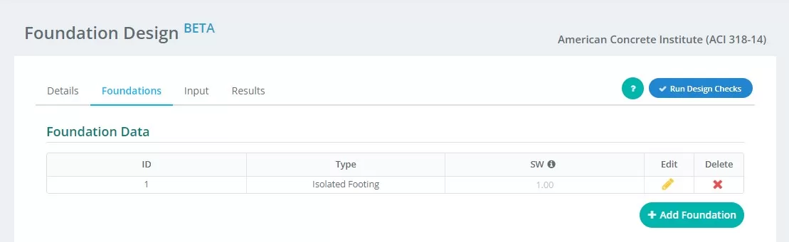
図 2. 基礎タブの詳細
に関する入力の要約 “財団” タブ:
- 財団ID – 各財団に数値識別を割り当てる.
- タイプ – 選択する “孤立した財団” ドロップダウンメニューから.
- SW – 自重係数
- 編集する – これをクリックしてデータの入力を開始し、ファンデーションを編集します
- 消去 – 基盤を削除するには
III. 入力
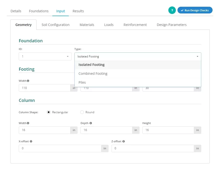
図 3. の選択 孤立した基礎 ドロップダウンメニュー.
ユーザーは、図に示すように基礎のタイプを確立できます 3, 選択する “孤立した基礎” このビューを表示するには.
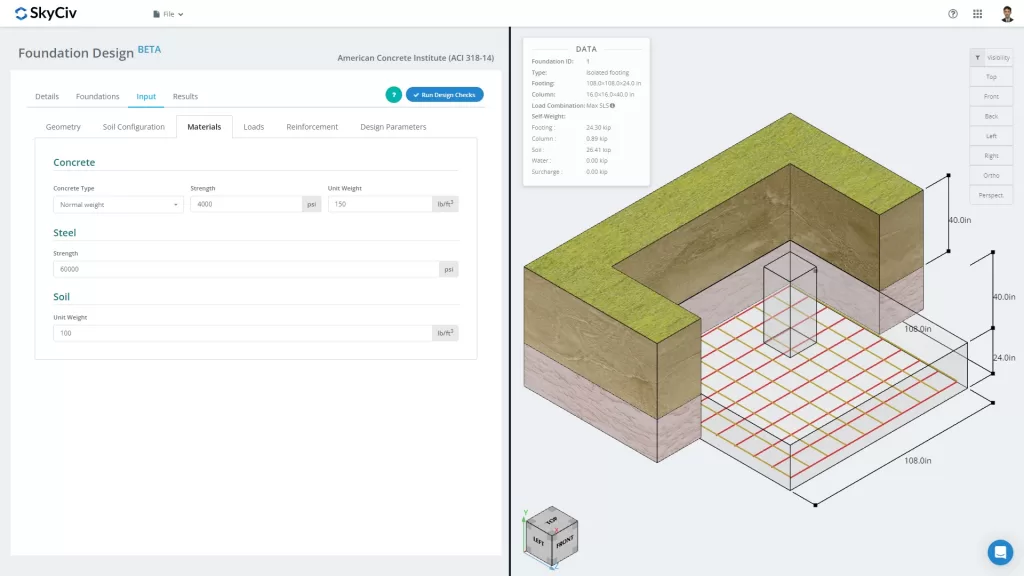
図 4. ファウンデーションタブ
の “入力” タブはジオメトリを含む入力カテゴリを区切ります, 土壌構成, 材料, 負荷, 補強とその他. これらの入力により、画面の右側のタブにある 3D グラフィックスが自動的に更新されます。. 適切なコンテナについては、このドキュメントの最後の部分で説明します。.
さまざまな入力カテゴリをもう少し詳しく見てみましょう:
ジオメトリ
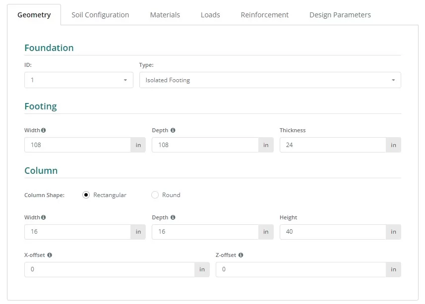
図 5. ジオメトリ 左側のタブ.
図を参照 6 そして 7 基礎と柱の寸法の命名法について:
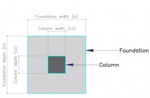
図 6. 指定のある財団
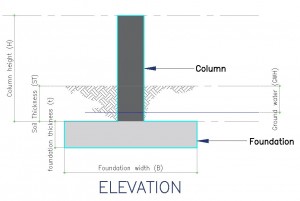
図 7. 財団の立面図
土壌構成
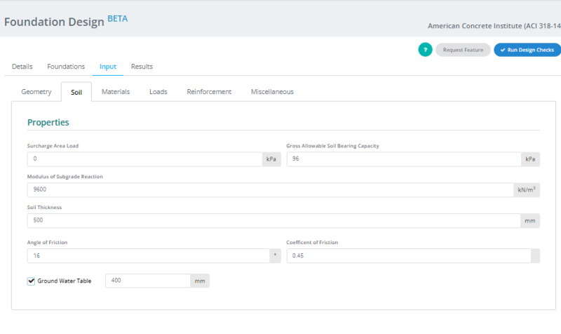
図 8. 土壌構成 左側のタブ.
注意:
- 土壌値は通常、地質工学レポートに記載されています。.
- にチェックを入れます “地下水位” 地下水の高さを定義するボックス.
- 「総許容地耐力」の値が変化すると、路床反力係数の値が自動的に更新されます。” 変更されます. しかしながら, ユーザーは引き続きこの値を上書きできます.
材料
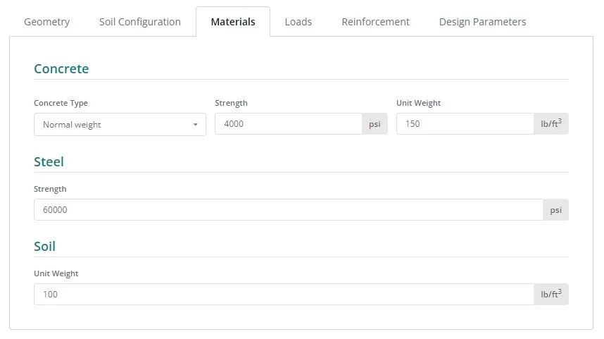
図 9. 材料 左側のタブのボタン.
負荷
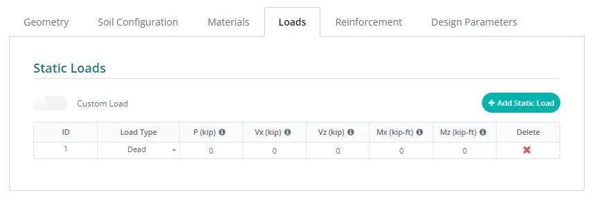
図 10. 負荷 左側のタブのボタン.
強化
通常, 隔離フーチングには底部の補強材のみが含まれます, ただし、対応するボタンをクリックすると上部補強のオプションにアクセスできます。. 補強の更新は簡単です, ドロップダウンリストからバーのサイズを選択し、必要な間隔を入力します。.
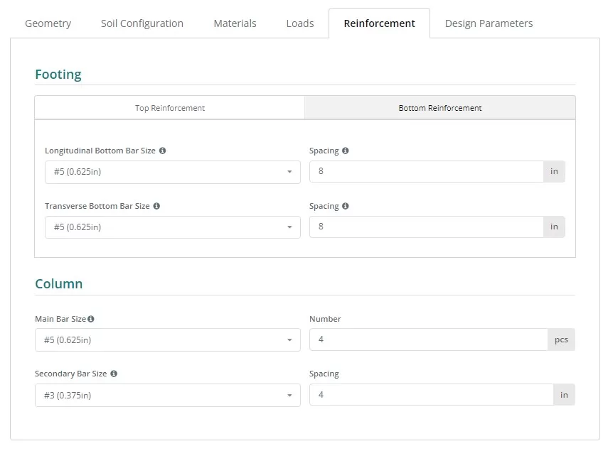
図 11. 強化 左側のタブのボタン.
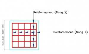
図 12. 補強の詳細.
鉄筋コードリファレンス:
- ASTM615 – 米国材料試験協会 615 : コンクリート補強用の変形およびプレーン炭素鋼棒の標準仕様
- N – オーストラリアの鉄筋クラスN
- PNS49 – フィリピン国家標準 49 : コンクリート補強用棒鋼 – 仕様.
- E2 – ユーロコード鉄筋 P
雑多
このタブには、選択した設計コードに必要なその他の入力が含まれています. また、有限要素モデルのメッシュ サイズとパンチングせん断チェック用のパンチングせん断エッジ係数を制御するための入力も含まれています。.
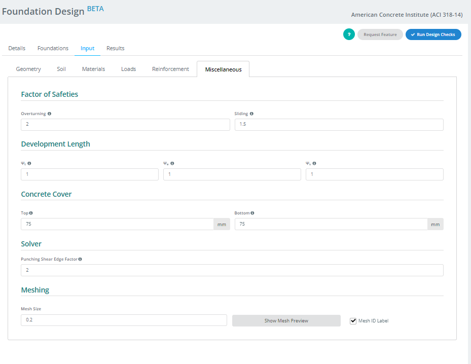
図 13. 雑多 左側のタブのボタン.
IV. 結果
「Run Design Check」ボタンをクリックすると、デザインによって結果テーブルが生成されます。. 各列, 最後の2つを除いて, Foundationモジュールによって完了した設計チェックを表します. 数値は利用率です; 以下のもの 1.0 パスです, そして何でも 1.0 失敗です. 最後の 2 列には、色分けされたステータスと、HTML または PDF 形式でレポートにアクセスまたはダウンロードするためのオプションが含まれています。.
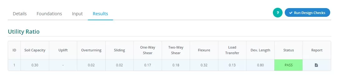
図 14. 結果 左側のタブの出力.
列表現の要約:
- 土圧
許容土圧に対する経験荷重による土圧の比率. - 隆起
荷重に隆起が存在するかどうかを判断します - 転覆
許容転倒モーメントに対する経験転倒モーメントの比率. - スライディング
すべり抵抗に対するすべり力の比率. - 一方向せん断
容量に対する一方向せん断需要の比率. - 二方向せん断
容量に対する双方向せん断需要の比率. - たわみ
曲げ能力に対する曲げ需要の比率. - 荷重伝達
公称耐力強度と実際の耐力強度の比. - 開発期間
公称開発長と実際の開発長の比率. - 状態
基礎設計が 合格 または 不合格 - 報告する
クリックすると基礎設計の詳細な計算が表示されます.
V . レンダラー
最後に, 画面の右側には、ユーザーが入力を視覚化するのに役立つ 3D レンダラーがあります。. 左上隅には、基礎に関する基本情報を含むモデルの概要データがあります。, 反対側の角には可視性の設定があります. ユーザーは表示または非表示にしたいオブジェクトを選択し、表示したいグラフィックの方向を選択できます。.
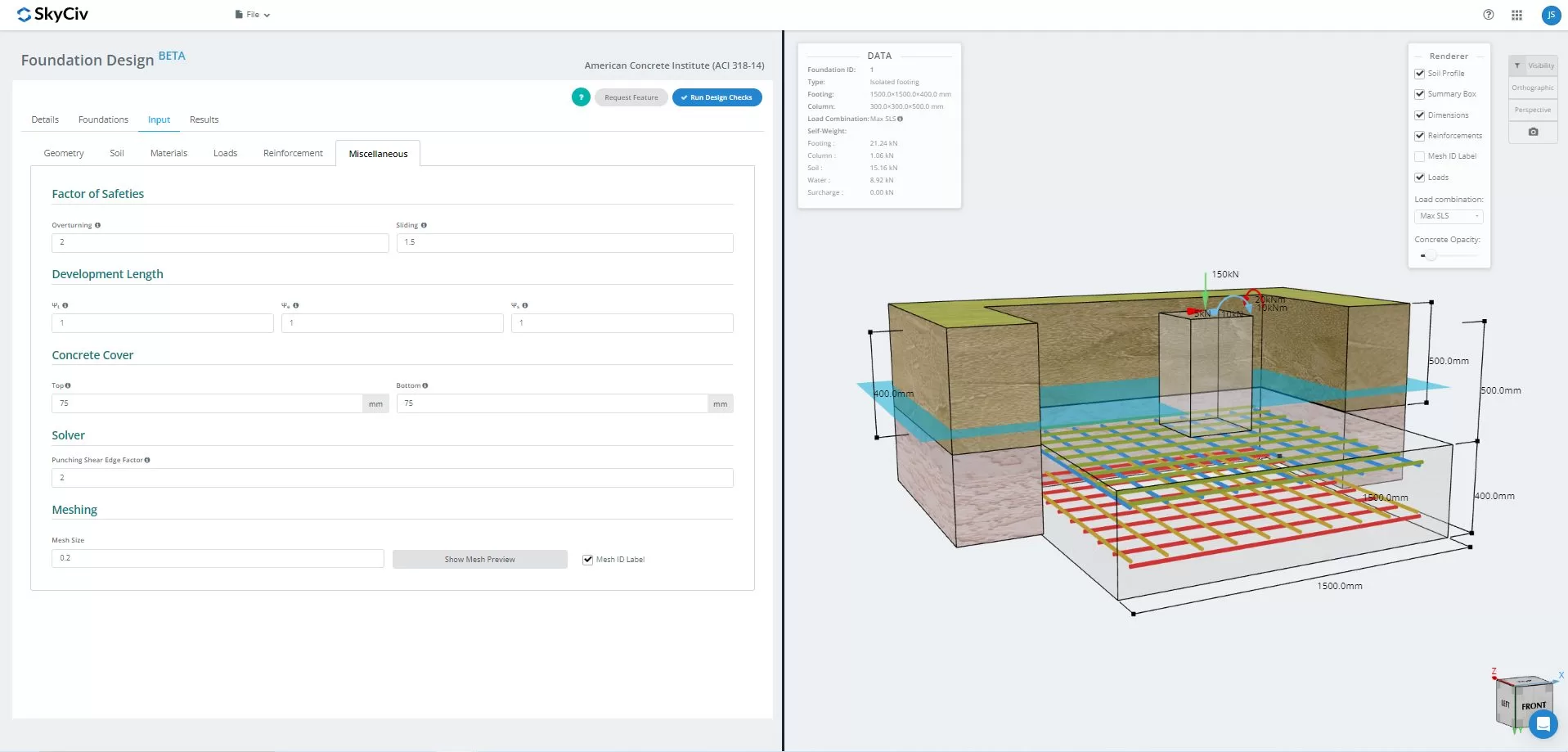
図 15.3D モデルのグラフィック表現
解決したら, ユーザーはFEA結果の土圧を表示できます, 3D での木甲板分析. 結果はすべての荷重の組み合わせにわたって切り替えることができます, 封筒ケースも含めて. 現在のビューのスクリーンショットもダウンロードできます.
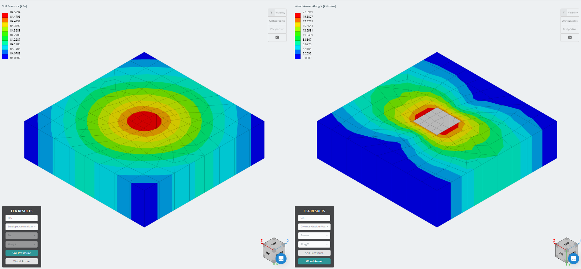
図 16. 有限要素解析結果
SkyCivのFoundationDesignソフトウェアを試してみたい? 当社のツールを使用すると、ダウンロードやインストールを行わずに基礎設計の計算を実行できます。!
参照:
- 構造コンクリートの建築基準要件 (ACI 318-14) 構造コンクリートの建築基準要件に関する解説 (ACI 318R-14). アメリカコンクリート学会, 2014.
- テイラー, アンドリュー, et al. 鉄筋コンクリート設計ハンドブック: ACI-318-14のコンパニオン. アメリカコンクリート学会, 2015.