Rigid Member の概要と使用例
剛体メンバーは強力で効果的なメンバー クラスです, 完全に剛性の高い部材をシミュレートするために使用できます。. ある場所から別の場所に力を伝達するためによく使用されます。, 何らかの任意の手段を介して, 想像上の, 無限に硬い部材. 仕組みの詳細については、以下のビデオをご覧ください。, ソフトウェアでモデル化する方法, そしていくつかのユースケース:
剛体メンバーの使用方法
メンバーを剛体として設定するには, メンバーを指定するだけです “タイプ” なので “リジッドリンク”. 注意: を切り替える必要があるかもしれません アドバンストモード 見に行きます タイプ 属性:
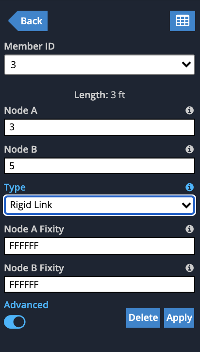
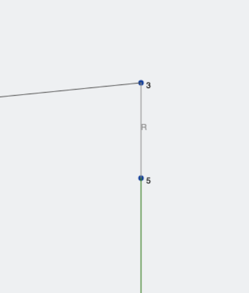
オプションが折りたたまれていることに気づくでしょう (リジッドリンクには必要ないため、) ただし、エンドフィックスを制御することはできます, これは基本的にどの荷重が転送されるかを制御します. 一度クリックすると 適用する, 剛体リンクが明るい灰色で描画されていることがわかります。 “R” その横にある記号:
使用例
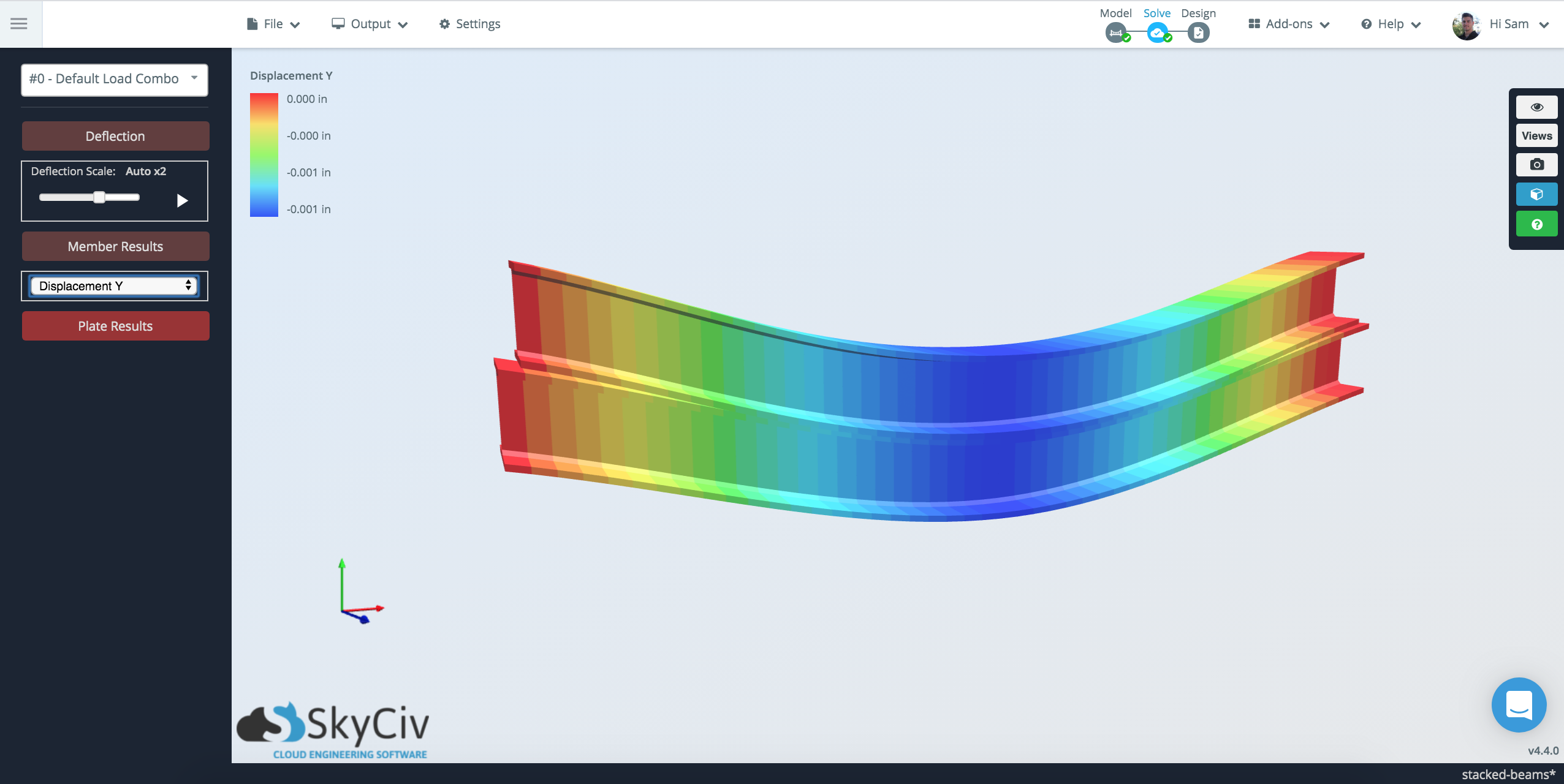
積み上げ梁

プレート間のラインヒンジ
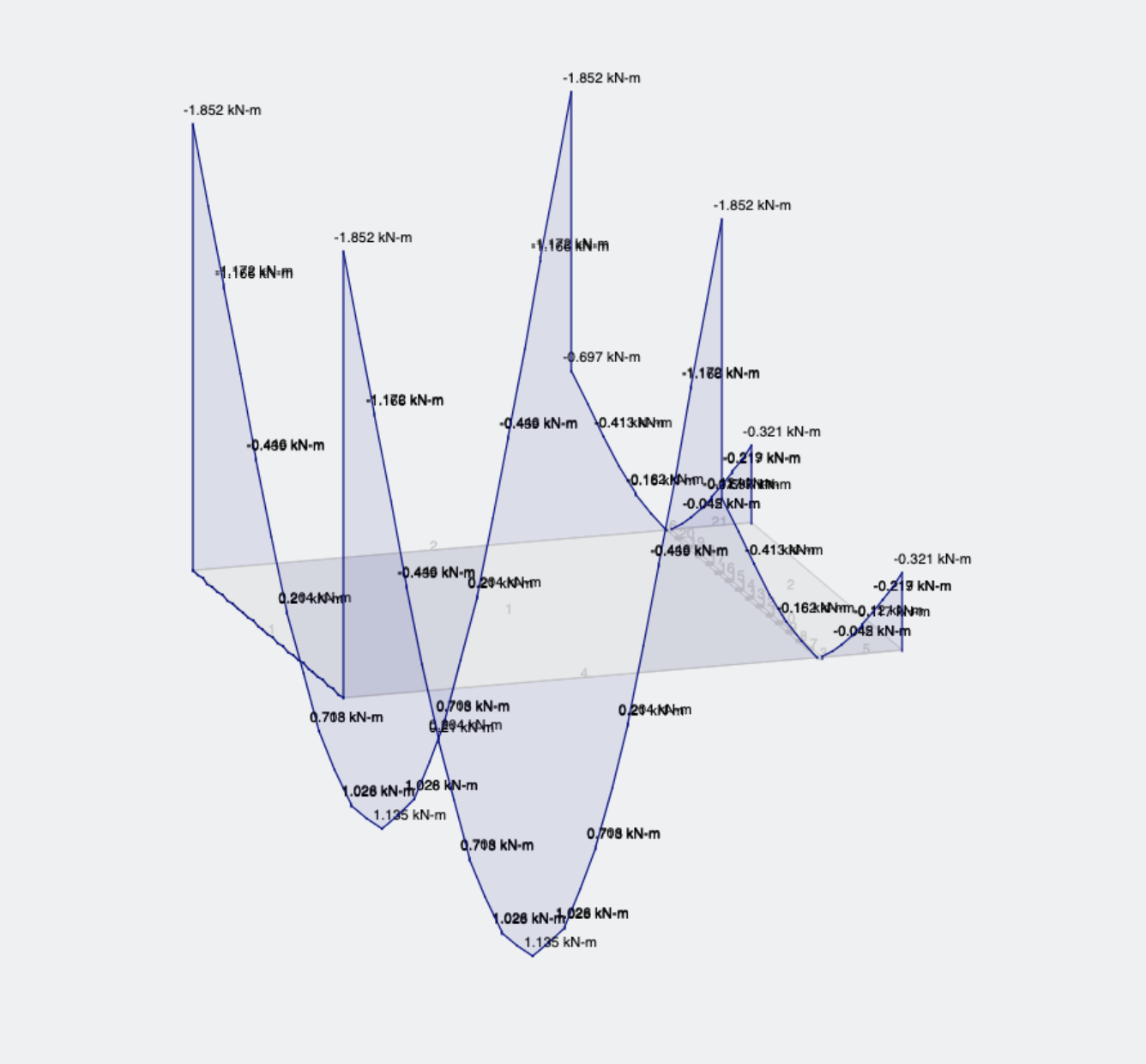
剛体リンクは、構造または要素間の剛体接続を定義するのに役立ちます. 彼らはしばしばメンバーを結合する想像上の堅いリンクとして考えられます。 一緒に平行移動および/または回転. 剛体リンクを使用して、メンバーのオフセットまたは接続を手動で制御することもできます。. さらに、リジッド リンクの固定/解放を変更して、接続先に対してどのような力と影響を与えるかを制御できます。. この良い例は、ヒンジでプレートを接続するライン ヒンジをシミュレートすることです。:
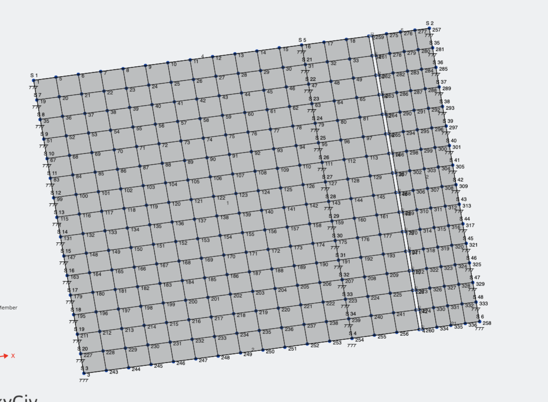
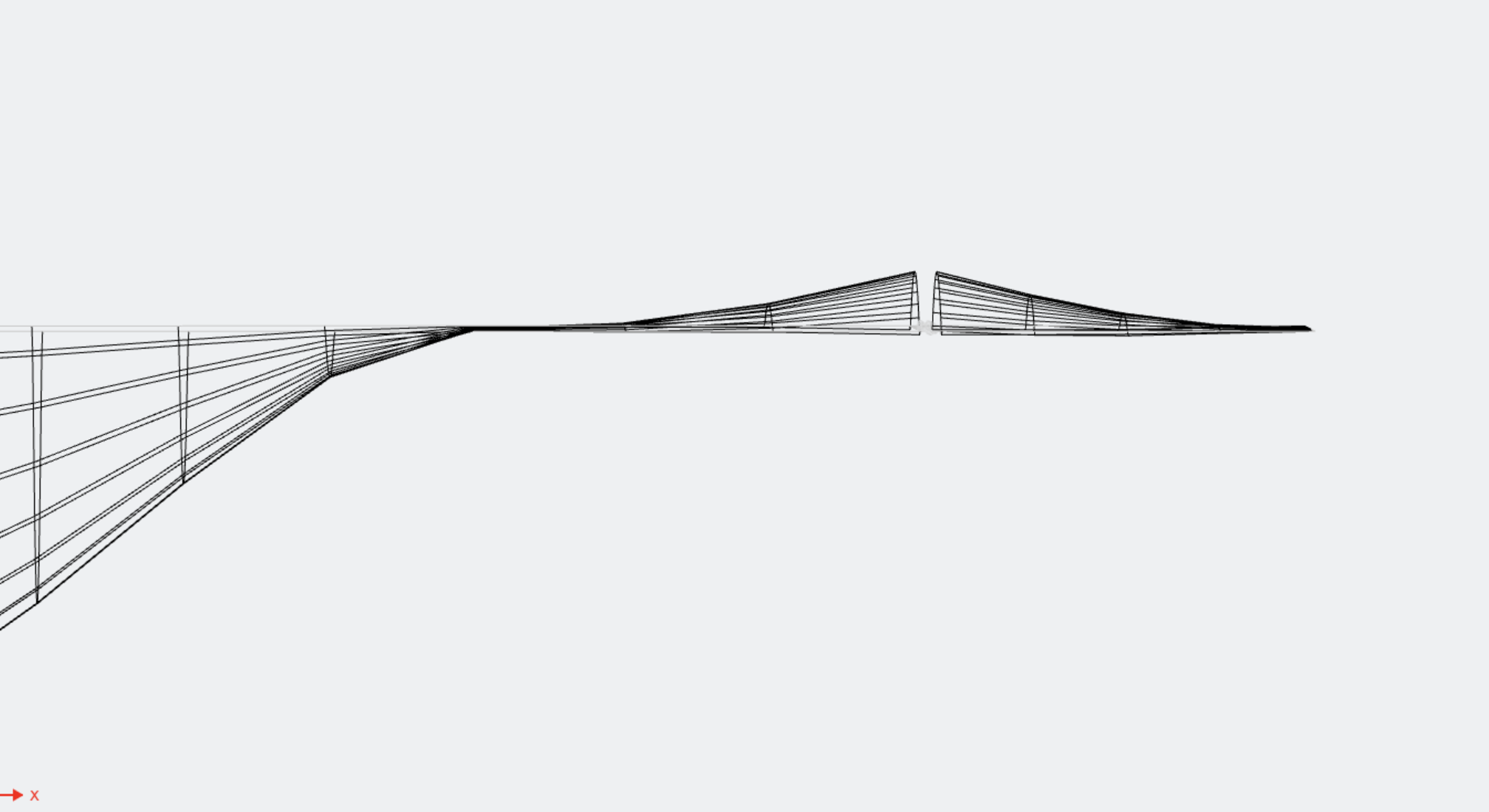
プレートを 2 枚追加することから始めます (ヒンジで結合したい場合) そして、それらを端部固定FFFFRRを備えた剛体メンバーに接続します. これらの堅固なリンクは、下に見られるプレートの隙間を接続しています。:
一般的な問題のトラブルシューティング
マスター/スレーブ接続
リジッド リンクを使用するときにソルバーから発生する最も一般的なエラーの 1 つは次のとおりです。:
“エラーコード 182: ノード #5 マスターノードです (ノードA) メンバーの #17 リジッドリンクのため、スレーブノードとして使用できません (Node B) 別のリジッド リンク メンバーの. これは、リジッド リンクに接続されているオフセットが原因である可能性があります。. この問題を回避するには、オフセットまたはリジッド リンクを削除してください。”
このようなエラーが発生した場合は、このガイドがこの種の問題の解決に役立ちます. この問題は、マスター ノードが多数のスレーブ ノードを持つことができるために発生します。. しかしながら, スレーブ ノードはマスター ノードを 1 つだけ持つことができます. 簡単に言えば, 単一のマスターとそこから来る多数のスレーブを維持します. 以下の例を考えてみましょう, 上記のエラーの原因となっていたのは:
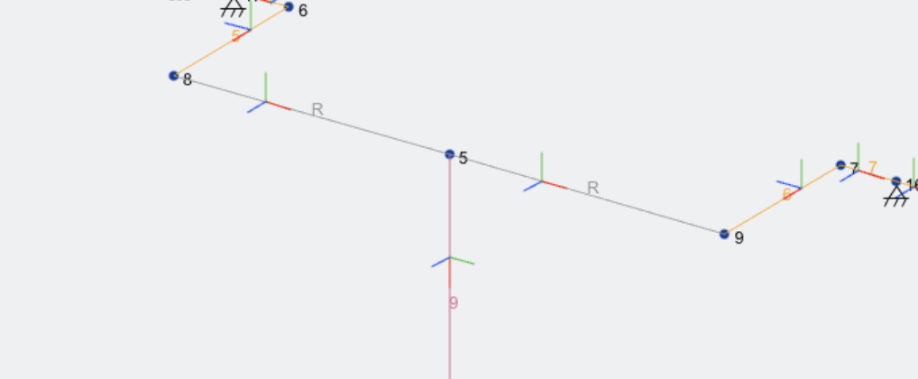
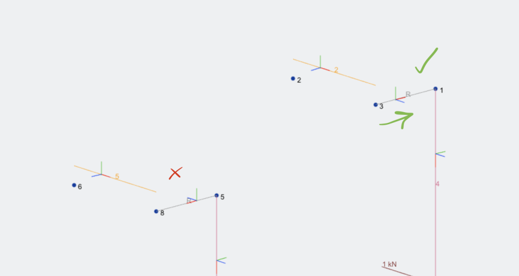
あなたができる最善のことは、 ローカル軸をオンにする マスターからスレーブへの方向を赤い線で示します (メンバーのローカル X 軸). 赤い線が左から右に流れているのがわかります。これは、あるメンバーのスレーブが別のメンバーのマスターでもあることを示しています。.
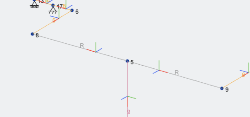
これを修正するには, 最初のメンバーのノード ID を反転すると、この動作が得られます, 堅実なメンバーたちと 流出する 単一ノードから:
オフセット付近でのリジッド リンクの使用
これは上記の問題と非常によく似ています, ただし、オフセットを使用すると自動的に発生する可能性があります。. オフセットあり, マスター ノードは常にメンバーのオフセット元のノードです。. 校長は上記と同じです, これが機能することを確認するために, オフセットノードから始まる剛体メンバーが常に存在します。. もう一度, メンバーのローカル軸は次のようになります。 流れ出します:
隣接するダイヤフラム
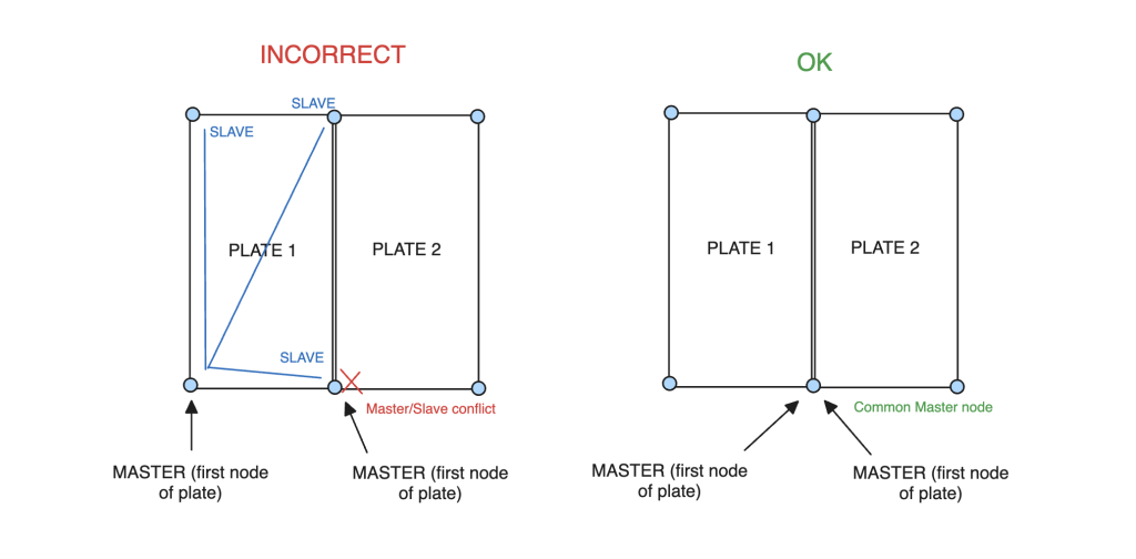
2 つのダイヤフラムを接続すると、マスター/スレーブの問題が発生する可能性もあります. ダイヤフラム内のマスター ノードは次のとおりであることに注意することが重要です。 常に最初のノード. これにより、接続された 2 つのダイヤフラムに共通のマスター/スレーブ ノードがある場合に問題が発生する可能性があります。. したがって、2 つの隣接する剛性ダイヤフラムが必要な場合は、, そのように設定する必要があります:
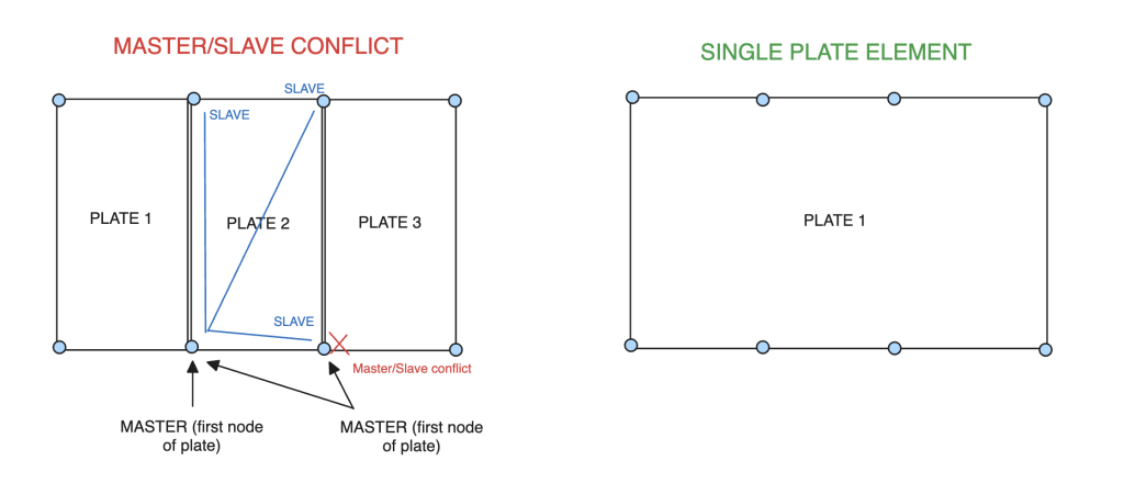
ダイヤフラムが 3 つ以上ある場合、問題が悪化する可能性があります, 共通のマスターノードを共有する方法がないため. この場合, プレート全体を単一の剛性ダイヤフラムに交換する方が良いでしょう。, 以上のものを手に入れることができることを覚えておいてください 4 プレートのノード, したがって、これはほとんどの場合、かなり許容できる回避策となるはずです:
スレーブはサポートになれません
これは一般的な構造解析の制限です.