Selecting Initial Sections
Start by modelling your usual structure, today we’ll be reviewing a model that has a Universal Beam for the beams, HSS sections for the columns and Equal Angle sections for the bracing. You can pretty much start with whatever sections you like, however we usually recommend selecting a section that you best guess will work. Here’s the model we’ll be optimizing:
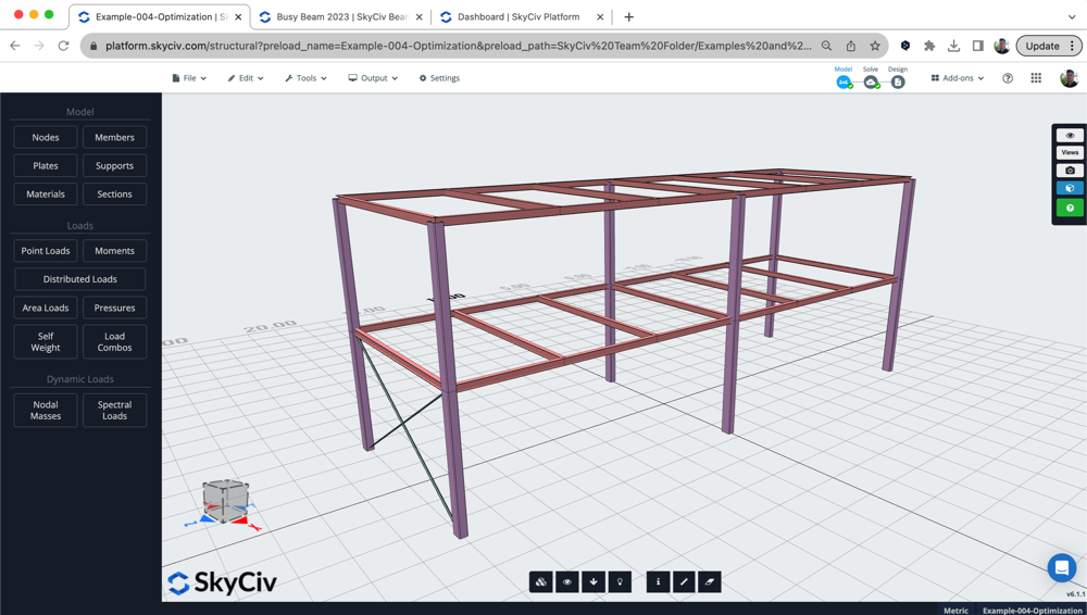
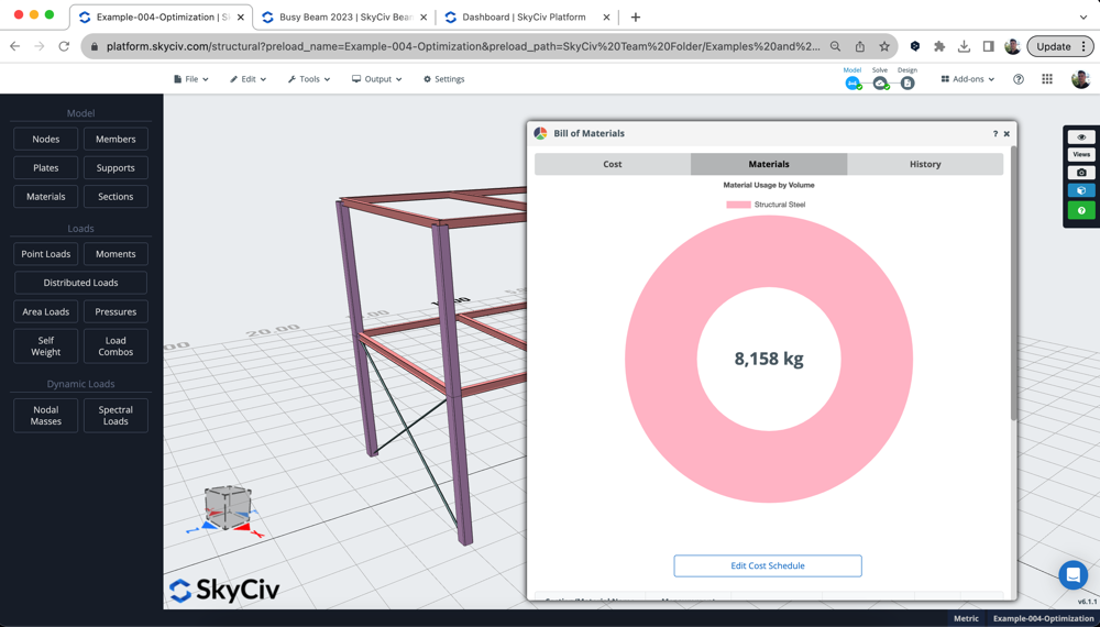
The model had load combinations, live/dead/wind loads and the proper restraints already setup. We also wanted to look at the initial material usage of this design. We use the Bill of Materials App to calculate the amount of material being used in the initial design:
Review Design Results + Set the Settings for Optimization
It’s usually a good idea to review where the design is at initially by running the design check for the model. In this example, we’ll be using Eurocode for the steel design check, but you can just as easily run the design check for the following:
- Steel – AISC, CSA, AS, BS, IS
- Timber – NDS, AS1720
- Cold Formed Steel – AISI, AS4600
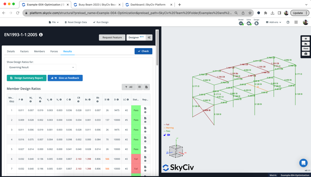
After reviewing the results, we could see the following:
- Universal Beams: Were failing, but only by a bit, with a utility ratio of about 110%. We want to optimize these to get them passing
- HSS Columns: were all passing, but very low utility (23%) so we felt we could optimize and reduce the material used here
- Bracing Members: these EA sections were all failing, with a utility of about 300%. We want to find the most optimal section that passed the design requirements
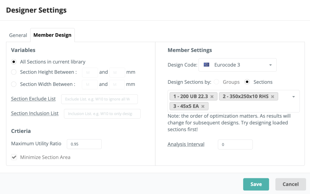
Accordingly, we wanted to run an Optimization using the Designer with the following settings. We want to design all 3 sections, with the analysis interval set to 0 (meaning the analysis won’t re-run after testing every section):
Reviewing the Results of the Designer
Once the designer runs, we receive the following popup – showing the optimal sections selected at a glance:
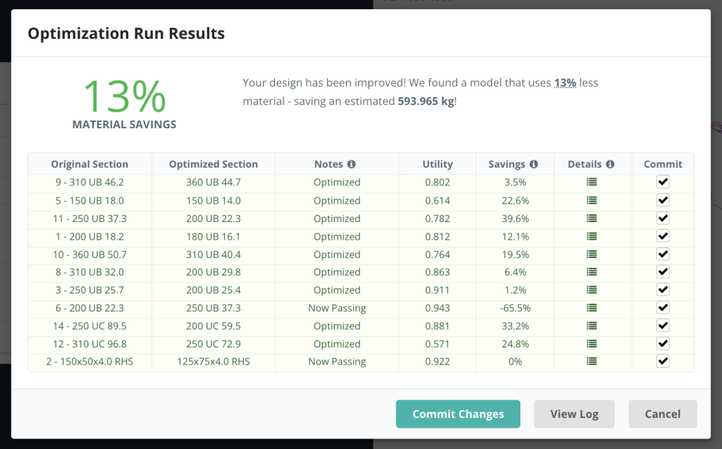
Note: the above screenshot shows the most up-to-date UI. Results are from a different model and do not match those in this tutorial
The Designer was able to find passable results for all the sections. Here were the results:
- Section 1 was slightly increased, found a workable solution at 94.9% utility
- Section 2 section seize was drastically reduced, and able to find a workable section at 88.6% utility
- Section 3 was previously failing, and now passing under a larger section but optimized at 83.2%
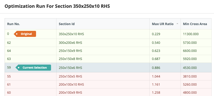
We can also review all the runs for each section by clicking the Iterations icon. This will display more information on all the sections tested. For example, looking at Section 2 above we can see it was only previously 22.9% utilized, and is not at 88.6%:
Committing Sections Suggested by the Designer
Once you’re happy with the proposed sections, click Commit Changes. The software will then re-solve the model and re-check the sections. In our video, you’ll see the results not matching with the Designer for Section 1. This is because the analysis interval was set to 0 – meaning the analysis results (particularly deflection) was not updated during the optimization process.
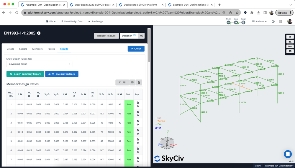
So, we re-ran the Designer – this time just Section 1 and with the Analysis Interval set to 1. After committing the changes again, we have a fully designed model with all the sections optimized to this design standard:
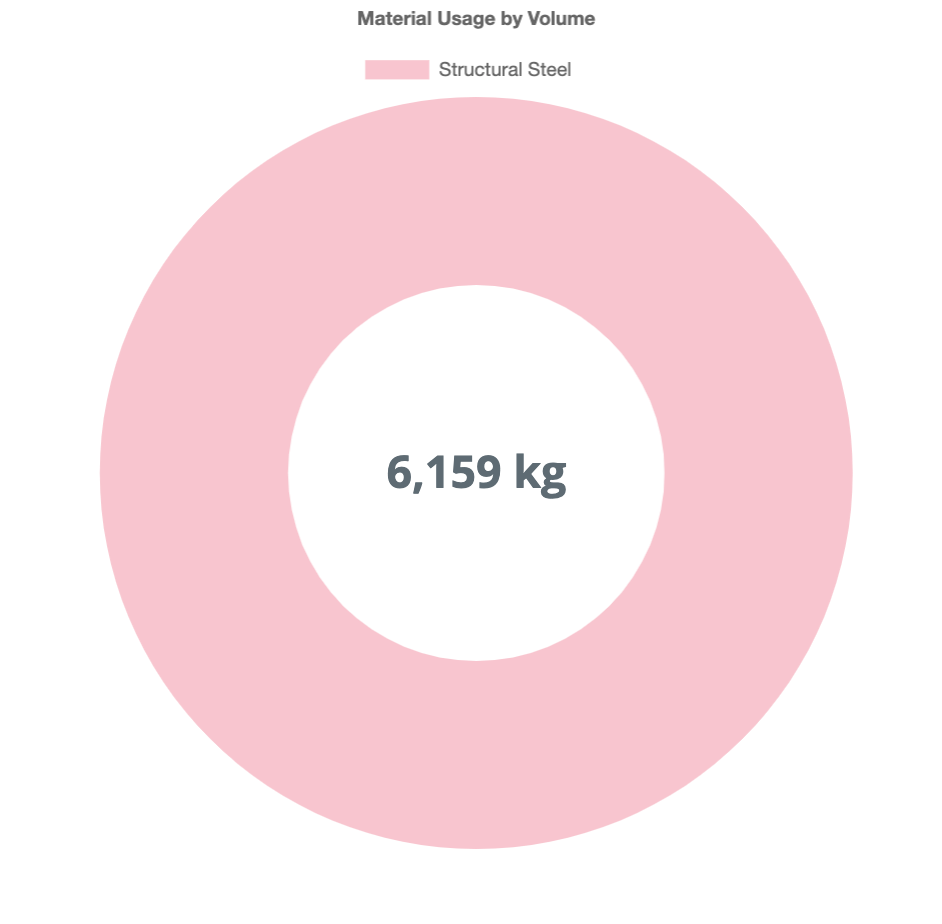
We can also now review the cost savings using the Bill of Materials App used in the first step, which shows we have reduced the structural model by about 2,000kg – resulting in almost 25% less material.
Optimizing Using SkyCiv Beam
We can also optimize single beams, using the SkyCiv Beam product. Combined with the above designer, we’re able to get quick and simple results for the optimal section. We can do this in 3 simple steps:
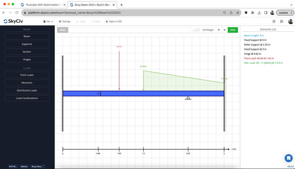
1. Build your Model – build your model the same way you always do, in this case we used a Canadian HSS section:
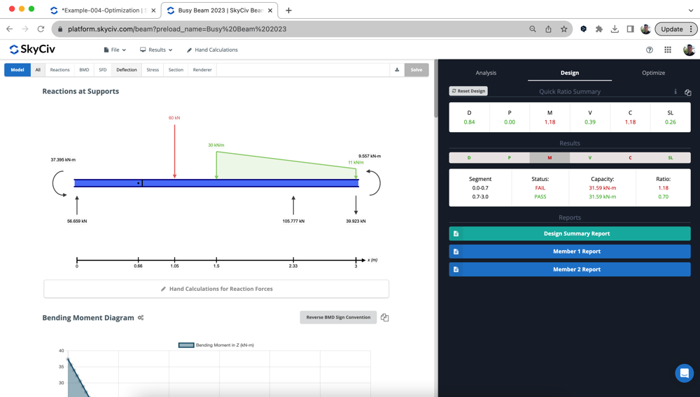
2. Review initial results – run Design (as per CSA S16 in this example) to see where our design is initially at. In the below example, the section is failing by about 20%:
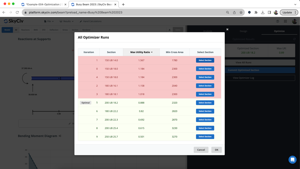
3. Run the Designer – run the Designer under Optimize with your desired sections and review your results. The most optimal section will already be selected, ready for you to commit to your model:
FAQ
We have two recommendations here:
- Large Models – Set Analysis Interval to 0 – this will run faster and return some pretty close results. However, there may be a mismatch of results, so might require a second re-run for a section
- Smaller Models – Set Analysis Interval to 1 – This way you have the most accurate results since we are re-running the solver between each cross section
- Medium Size – set analysis interval t0 5 – this will balance the need for accuracy and speed.
The Designer supports all of the member design modules in S3D, including:
- Steel – AISC, CSA, AS, BS, IS
- Timber – NDS, AS1720
- Cold Formed Steel – AISI, AS4600
For SkyCiv Beam, all of the above, except for the wind modules, are supported.


