
AISCを使用したベースプレートのデザイン例 360-22 およびACI 318-19
問題ステートメント
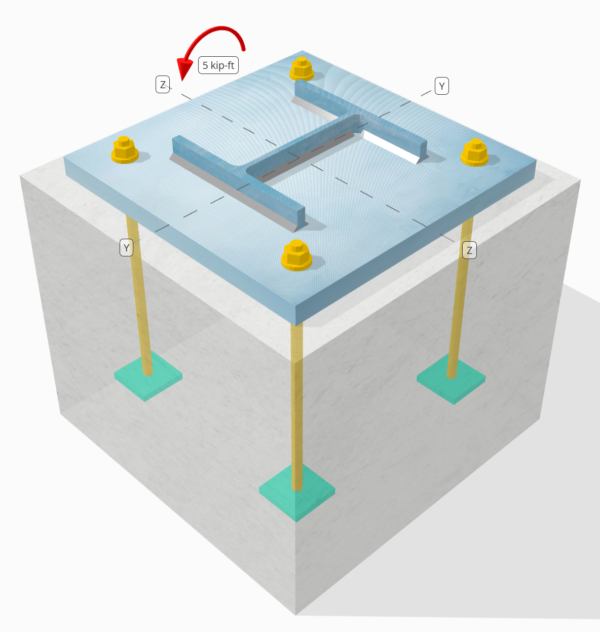
設計された柱とベース プレートの接続が十分な接続であるかどうかを判断します。 5 kip-ft strong-axis moment.
指定されたデータ
カラム:
列セクション: W8x31
列エリア: 9.130 に2
列素材: A992
ベースプレート:
ベースプレートの寸法: 15 xで 15 に
ベースプレートの厚さ: 1 に
ベースプレート材料: A36
コンクリート:
具体的な寸法: 18 xで 18 に
コンクリートの厚さ: 15 に
コンクリート材料: 3000 psi
溶接:
溶接サイズ: 1/4 に
フィラー金属分類: E70XX
溶接のみを介して伝達される圧縮負荷? いいえ
SkyCiv 無料ツールでモデルを作成する
無料のオンライン ツールを使用して、上記のベース プレート設計を今すぐモデル化してください。! サインアップは必要ありません.
Determine if Low Moment or Large Moment
The calculations for this base plate example, which is subjected to a strong-axis moment, will be based on AISC 設計ガイド 1, 3RDエディション. According to the design guide, base plates subjected to moment loads only are classified as the Large Moment Case. This is because no axial load is present to counteract the eccentric load acting on the connection.
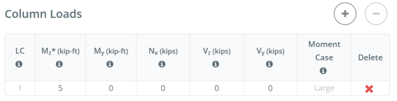
For other load combinations, such as strong-axis bending with axial compression or strong-axis bending with axial tension, determining if the case is Large Moment or Low Moment depends on the actual 列サイズ, base plate size, concrete size, and the given 負荷.
In the free version of SkyCiv, the moment case is displayed as you enter the load values. You can access the free tool here to determine the moment case yourself. Straight from the browser, インストール不要.
To learn more about Low Moment and Large Moment case, refer to this SkyCiv article: AISC DG1: モーメントの大きいベースプレートとモーメントの小さいベースプレート
段階的な計算
小切手 #1: Weld capacity
We start the design by checking the weld capacity of the connection. We use the Blodgett equations from 溶接構造の設計 オマー・W著. Blodgett to determine the weld section modulus of the weld. We take the weld shape shown below as a simplification.
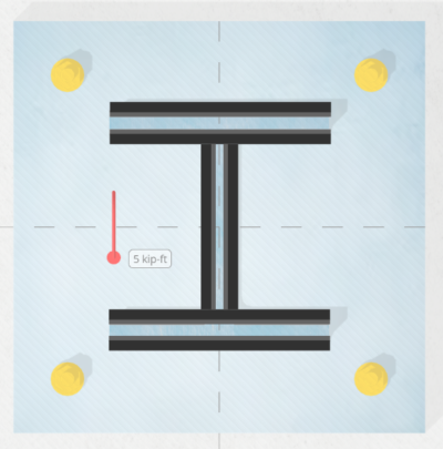
\(S_w = 2d_{col}b_f + \dfrac{(d_{col})^2}{3} = 2 \times 8 \text{ in} \times 8 \text{ in} + \dfrac{(8 \text{ in})^2}{3} = 149.33 \text{ in}^2\)
次, we divide the applied bending moment by the weld section modulus to determine the weld stress per unit length. Note that in calculating the weld section modulus, we assume the critical weld stresses occur at the outermost fiber. For a weld in an I-shaped section, the critical locations are at the outer flanges. We get the weld stress as:
\(r_{uw} = \dfrac{M_z}{S_w} = \dfrac{5 \text{ kip·ft}}{149.33 \text{ in}^2} = 0.40179 \text{ kip/in}\)
その後, を計算します capacity of the weld. のために 0.25 in weld size, the design weld throat is 0.177 に, which is obtained by multiplying the weld size by \(\dfrac{\sqrt{2}}{2}\). 使用する AISC 360-22 Eq. J2-4, the weld capacity per unit length is:
\(\phi r_n = \phi 0.6F_{exx}E_w k_{ds} = 0.75 \times 0.6 \times 70 \text{ ksi} \times 0.177 \text{ in} \times 1 = 5.5755 \text{ kip/in}\)
以来 0.40179 KPI < 5.5755 KPI , the column weld capacity is 十分な.
This weld check investigates the weld stress at the tension flange. Since the geometry is symmetric and the only load is a moment acting at the center, we can assume the stress at the compression flange is the same as the stress at the tension flange. したがって, the welds at the compression flange also have enough capacity.
この設計例では, しかしながら, the design inputs specify that compression is not transferred through the welds, but through ベアリング. したがって, in the next check, we evaluate the bearing capacity of the column.
小切手 #2: Calculate column bearing capacity
After evaluating the weld capacity, we make sure the column has enough capacity to bear on the base plate. This is necessary because we assume the welds do not carry the compression load.
最初, を決定します compressive stress at the critical section, which is still the flange. We then add any contribution from axial compression. この場合, there is none.
\(r_u = \dfrac{N_x}{A_{col}} + \dfrac{M_z 0.5d_{col}}{I_{zz,col}} = \dfrac{0 \text{ kip}}{9.13 \text{ in}^2} + \dfrac{5 \text{ kip·ft} \times 0.5 \times 8 \text{ in}}{110 \text{ in}^4} = 2.1818 \text{ ksi}\)
その後, を使用しております AISC 360-22 Section J7 Eq. J7-1 を決定する 支持力:
\(\phi r_n = \phi 1.8F_{y\_col} = 0.75 \times 1.8 \times 50 \text{ ksi} = 67.5 \text{ ksi}\)
以来 2.1818 KSI < 67.5 KSI, 列ベアリング容量はです 十分な.
通常, this check is not governing.
小切手 #3: コンクリートベアリング容量を計算します
To calculate the concrete bearing capacity, we need two areas. See the figure below as a guide.
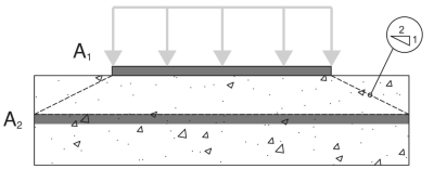
- A1 – Base plate loaded area
- A2 – Area of the concrete support with the same shape as A1
A1 それは loaded area of the base plate, その間 A2 それは same loaded area projected at a 2H:1V slope into the concrete support. More details on these areas can be found in ACI 318-19 セクション 22.8.3.2.
これで base plate design with moment, the A1 area will be calculated using the full width of the base plate, \(B\) そしてその actual bearing length, \(Y\). The actual bearing length is measured from the edge of the base plate at the compression side towards the center of the plate.
\( A_1 = B \times Y \)
For most engineers, calculating A1 and A2 requires a lot of work, so they simply assume A1 = A2, どちらが保守的ですか. 構造が非線形の振る舞いを示す場合、非線形または2次の静的解析が適しています SkyCIVベースプレートソフトウェア, 反復 are performed to determine the actual A1 values and to maximize the capacity of the base plate.
The table below shows the iteration steps from SkyCiv to determine the bearing length Y, そしてその後, to determine the actual A1 and A2 areas.

最初, an initial Y is assumed, and the A2 and A1 values are calculated based on the initial Y. These are then used to calculate the maximum bearing strength of the concrete, \(f_{p\_max}\), そして対応する bearing force per unit length, \(q_{max}\). Once these are determined, the corresponding Y value is determined based on Eq. 4-32 of AISC DG1 3rd 版. If the calculated Y does not match the initial Y, another iteration step is performed. A more detailed step-by-step calculation of the last iteration is shown in the next section.
今, taking the A2 and A1 values from the iteration, を使用しております Eq. 4-2 of AISC Design Guide 1, 3RDエディション, to determine \(f_{p\_max}\), the design bearing strength for concrete crushing:
\(f_{p\_max} = \phi \left( \min \left( 0.85 \, (f_c’) \sqrt{\dfrac{A_2}{A_1}}, \, 1.7 \, (f_c’) \right) \right)\)
\(f_{p\_max} = 0.65 \times \left( \min \left( 0.85 \times (3 \text{ ksi}) \times \sqrt{39.941}, \, 1.7 \times (3 \text{ ksi}) \right) \right) = 3.315 \text{ ksi}\)
さらに, since this design is a Large Moment Case, the base plate has both a compression side and a tension side. この状況では, we should allow the concrete bearing to be at its full capacity and minimize the Y value. そう, any remaining tensile force, based on equilibrium of forces, will be taken by the anchors at the tension side.
Given this, we set \(f_{p\_actual}\) に等しい \(f_{p\_max}\).
\(f_{p\_actual} = f_{p\_max} = 3.315 \text{ ksi}\)
以来 3.315 ksi ≤ 3.315 KSI, コンクリートベアリング能力はです 十分な.
小切手 #4: Calculate base plate yielding capacity at the bearing interface
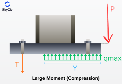
The next step is to determine if the base plate has enough capacity for the given load. As the moment load pushes the base plate against the concrete, the base plate has a tendency to yield due to flexure. We call this check the base plate yielding check on the bearing interface. There is also a separate yielding due to the tension load, and it will be covered in the next design check.
To check the base plate yielding, we need to determine the \(q_{max}\), which is the compression force per unit length. AISC DG1 3rd Ed. Eq. 4-37 与える \(q_{max}\)なので:
\(q_{max} = f_{p\_max}B_{bp} = 3.315 \text{ ksi} \times 15 \text{ in} = 49.725 \text{ kip/in}\)
その後, we will calculate the Y-dimension. Although the Y-dimension is already calculated in the prior check, this section will show how we use the equations from AISC DG1. For this Large Moment Case, を使用しております Eq. 4-32 of AISC DG1, 3RDエディション.
For the plus case:
\(Y_{case1} = \left( f + \dfrac{L_{bp}}{2} \right) + \sqrt{\left( \left( f + \dfrac{L_{bp}}{2} \right)^2 \right) – \dfrac{2M_z}{q_{max}}}\)
\(Y_{case1} = \left( 5.5315 \text{ in} + \dfrac{15 \text{ in}}{2} \right) + \sqrt{\left( \left( 5.5315 \text{ in} + \dfrac{15 \text{ in}}{2} \right)^2 \right) – \dfrac{2 \times 5 \text{ kip·ft}}{49.725 \text{ kip/in}}}\)
\(Y_{case1} = 25.97 \text{ in}\)
For the minus case:
\(Y_{case2} = \left( f + \dfrac{L_{bp}}{2} \right) – \sqrt{\left( \left( f + \dfrac{L_{bp}}{2} \right)^2 \right) – \dfrac{2M_z}{q_{max}}}\)
\(Y_{case2} = \left( 5.5315 \text{ in} + \dfrac{15 \text{ in}}{2} \right) – \sqrt{\left( \left( 5.5315 \text{ in} + \dfrac{15 \text{ in}}{2} \right)^2 \right) – \dfrac{2 \times 5 \text{ kip·ft}}{49.725 \text{ kip/in}}}\)
\(Y_{case2} = 0.092925 \text{ in}\)
Note that this equation has + そして – シンボル, so we get two values. ここから, we need to determine which value makes more sense. 以来 25.97 に is greater than the base plate length, 15 に, we will not consider this value. そう, 我々は使用するだろう 0.092925 に として ベアリングの長さ.
\(Y = Y_{case2} = 0.092925 \text{ in}\)
次, we calculate the cantilever lengths. これらは m and n dimensions from the figure below. これはに基づいています AISC DG1 3rd Edition Section 4.3.1.
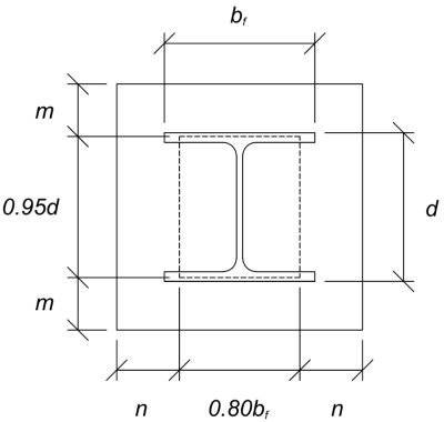
The calculated m and n cantilever values are:
\(m = \dfrac{L_{bp} – 0.95d_{col}}{2} = \dfrac{15 \text{ in} – 0.95 \times 8 \text{ in}}{2} = 3.7 \text{ in}\)
\(n = \dfrac{B_{bp} – 0.8b_f}{2} = \dfrac{15 \text{ in} – 0.8 \times 8 \text{ in}}{2} = 4.3 \text{ in}\)
その後, 私達はします compare the calculated Y value to the larger of m and n. Since Y is less than the larger cantilever length, 我々は使用するだろう AISC DG1 3rd Ed. Eq. 4-52a. This gives the required base plate thickness to be:
\(t_{p(req)} = \sqrt{\dfrac{4f_{p\_actual}Y \left( n – \dfrac{Y}{2} \right)}{\phi F_{y\_bp}}}\)
\(t_{p(req)} = \sqrt{\dfrac{4 \times 3.315 \text{ ksi} \times 0.092925 \text{ in} \times \left( 4.3 \text{ in} – \dfrac{0.092925 \text{ in}}{2} \right)}{0.9 \times 36 \text{ ksi}}} = 0.4022 \text{ in}\)
最後に, let’s compare it to the actual base plate thickness.
\(t_{p(actual)} = t_{bp} = 1 \text{ in}\)
以来 0.4022 に < 1 に, the yielding capacity of the base plate is 十分な.
小切手 #5: Calculate base plate yielding capacity at the tension interface
The required tensile force on the anchors at the tension side 等しい to the resulting compression force on the compression side. This is because the base plate is only loaded with moment loads, and so the resulting couple forces are equal in magnitude.
To calculate the required strength of anchors, を使用しております AISC DG1 3rd Ed. Eq. 4-31.
\(T_u = q_{max}Y = 49.725 \text{ kip/in} \times 0.092925 \text{ in} = 4.6207 \text{ kip}\)
その後, を計算します eccentricity of this tensile force from the column support. This is taken from the center of the anchor rod to the center of the column flange. 使用します Eq. 4-61 of the design guide to determine the eccentricity. In the equation, f is the distance of the anchor rod from the column centerline.
\(x = \left( f – \dfrac{d_{col}}{2} \right) + \dfrac{t_f}{2} = \left( 5.5315 \text{ in} – \dfrac{8 \text{ in}}{2} \right) + \dfrac{0.435 \text{ in}}{2} = 1.749 \text{ in}\)
Note that in this analysis, we take the whole base plate width as the section to resist the flexure, as we closely follow the AISC DG1 3rd Ed. guidelines. Other conservative bending widths could also be used.
最後に, we determine the required base plate thickness を使用して Eq. 4-62a.
\(t_{p(req)} = \sqrt{\dfrac{4T_u x}{B_{bp}\phi F_{y\_bp}}} = \sqrt{\dfrac{4 \times 4.6207 \text{ kip} \times 1.749 \text{ in}}{15 \text{ in} \times 0.9 \times 36 \text{ ksi}}} = 0.25791 \text{ in}\)
以来 0.25791 に < 1 に, の yielding capacity of the base plate is 十分な.
小切手 #6: アンカーチェック
The rest of the anchor design checks are not shown in this example. Please refer to other SkyCiv Base Plate Design Examples that covers capacity of 停泊地.
設計の概要
Skycivベースプレート設計ソフトウェアは、このデザインの例の段階的な計算レポートを自動的に生成できます. また、実行されたチェックとその結果の比率の概要も提供します, 情報を一目で理解しやすくします. 以下はサンプルの概要表です, レポートに含まれています.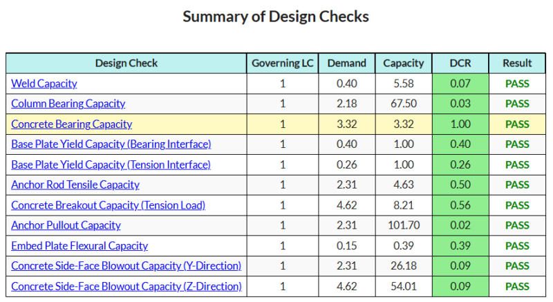
ベースプレートソフトウェアを購入します
他のSkyCIVモジュールなしで、ベースプレートデザインモジュールのフルバージョンを単独で購入する. これにより、ベースプレートデザインの完全な結果が得られます, 詳細なレポートとその他の機能を含む.

