AISCを使用したベースプレートのデザイン例 360-22 およびACI 318-19
問題ステートメント
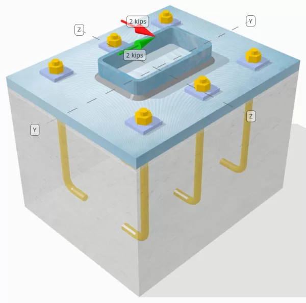
設計された柱とベース プレートの接続が十分な接続であるかどうかを判断します。 Vy=2キップ そして Vz=2キップ せん断荷重.
指定されたデータ
カラム:
列セクション: HSS7X4X5/16
列エリア: 7.59 に2
列素材: A36
ベースプレート:
ベースプレートの寸法: 12 xで 14 に
ベースプレートの厚さ: 3/4 に
ベースプレート材料: A36
グラウト:
グラウトの厚さ: 0.25 に
コンクリート:
具体的な寸法: 12 xで 14 に
コンクリートの厚さ: 10 に
コンクリート材料: 3000 psi
ひび割れまたは破損していません: 割れた
アンカー:
アンカーの直径: 1/2 に
効果的な埋め込み長: 8 に
プレートワッシャーの厚さ: 0.25 に
プレートワッシャー接続: ベースプレートに溶接
溶接:
溶接サイズ: 1/4 に
フィラー金属分類: E70XX
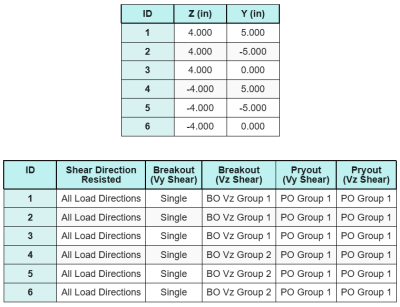
アンカーデータ (から SkyCIV計算機):
SkyCiv 無料ツールでモデルを作成する
無料のオンライン ツールを使用して、上記のベース プレート設計を今すぐモデル化してください。! サインアップは必要ありません.
定義
ロードパス:
設計は次の推奨事項に従っています。 AISC 設計ガイド 1, 3RDエディション, およびACI 318-19. 柱にかかるせん断荷重は溶接部を介してベースプレートに伝達されます。, そして支持コンクリートまで アンカーロッド. この例では、摩擦ラグとせん断ラグは考慮されていません。, これらのメカニズムは現在のソフトウェアではサポートされていないため、.
デフォルトでは, 適用された せん断荷重はすべてのアンカーに分散されます, 溶接プレートワッシャーの使用またはその他の工学的手段による. 各アンカーが運ぶ荷重は、次の 3 つの要素を使用して決定されます。 (3) に記載されている事例 ACI 318-19 句 17.7.2 とイチジク. R17.7.2.1b. 各アンカーは荷重を下の支持コンクリートに伝達します。. これらの参考文献に従った荷重分布は、荷重伝達の仮定の連続性を確保するためにアンカー鋼のせん断強度をチェックするときにも使用されます。.
代替として, ソフトウェアにより、簡素化されたより保守的な仮定が可能になります, ここで、せん断荷重全体は、 荷重されたエッジに最も近いアンカー. この場合, せん断容量チェックは、これらのエッジアンカーだけで実行されます.
アンカーグループ:
の SkyCYVベースプレート設計ソフトウェア どのアンカーが評価するためのアンカーグループの一部であるかを識別する直感的な機能が含まれています コンクリートせん断ブレークアウト そして コンクリートせん断格子 障害.
アン アンカーグループ 投影された抵抗領域が重複する2つ以上のアンカーとして定義されます. この場合, アンカーは一緒に行動します, そして、それらの組み合わせ抵抗は、グループの適用された負荷に対してチェックされます.
あ シングルアンカー 投影抵抗領域が他のものと重複しないアンカーとして定義されます. この場合, アンカーは単独で作用します, そして、そのアンカーに加えられたせん断力は、個々の抵抗に対して直接チェックされます.
この区別により、せん断関連の故障モードを評価する際に、ソフトウェアがグループの動作と個々のアンカーパフォーマンスの両方をキャプチャできます。.
段階的な計算
小切手 #1: 溶接容量を計算します
最初のステップは、を計算することです 総溶接長 せん断に抵抗するために利用可能. ベースプレートは列セクションの周囲に沿って溶接されているため, 総溶接の長さは、すべての側面の溶接を合計することで得られます.
\( L_{溶接} = 2 \左( =最も近いサポートの面までのせん断が考慮されているセクションの距離{col} – 2r_{col} – 2t_{col} \正しい) + 2 \左( d_{col} – 2r_{col} – 2t_{col} \正しい) \)
\( L_{溶接} = 2 \回 (4\,\テキスト{に} – 2 \時間0.291 、テキスト{に} – 2 \時間0.291 、テキスト{に}) + 2 \回 (7\,\テキスト{に} – 2 \時間0.291 、テキスト{に} – 2 \時間0.291 、テキスト{に}) = 17.344 、 text{に} \)
この溶接長を使用します, yの適用されたせん断力- Z方向は分割されて平均を決定します 単位長さあたりのせん断力 それぞれの方向に:
\( v_{あなた} = frac{v_y}{L_{溶接}} = frac{2\,\テキスト{キップ}}{17.344\,\テキスト{に}} = 0.11531 、 text{kip/in} \)
\( v_{に} = frac{V_Z}{L_{溶接}} = frac{2\,\テキスト{キップ}}{17.344\,\テキスト{に}} = 0.11531 、 text{kip/in} \)
の 合力せん断 単位長さあたりの需要 次に、正方形の合計の平方根を使用して決定されます (SRSS) 方法.
\( r_u = sqrt{(v_{あなた})^ 2 + (v_{に})^ 2} \)
\( r_u = sqrt{(0.11531\,\テキスト{kip/in})^ 2 + (0.11531\,\テキスト{kip/in})^ 2} = 0.16308 、 text{kip/in} \)
次, 溶接容量は使用して計算されます AISC 360-22 Eq. J2-4, ASを取得する方向強度係数を使用します KDS = 1.0 HSSセクションの場合. aの溶接容量 1/4 溶接では、として決定されます:
\( \phi r_n = phi 0.6 F_{exx} E_W K_{DS} = 0.75 \回 0.6 \時間70 、テキスト{KSI} \時間0.177 、テキスト{に} \回 1 = 5.5755 、 text{kip/in} \)
また、基本金属を確認する必要があります, 列とベースプレートの両方, を使用して AISC 360-22 Eq. J4-4 せん断破裂強度を取得します. これは与えます:
\( \Phi R_{NBM, col} = phi 0.6 F_{u _col} t_{col} = 0.75 \回 0.6 \時間58 、テキスト{KSI} \時間0.291 、テキスト{に} = 7.5951 、 text{kip/in} \)
\( \Phi R_{NBM, 血圧} = phi 0.6 F_{u _bp} t_{血圧} = 0.75 \回 0.6 \時間58 、テキスト{KSI} \タイム0.75 、テキスト{に} = 19.575 、 text{kip/in} \)
\( \Phi R_{NBM} = min 左( \Phi R_{NBM, 血圧},\, \Phi R_{NBM, col} \正しい) = min(19.575\,\テキスト{kip/in},\, 7.5951\,\テキスト{kip/in}) = 7.5951 、 text{kip/in} \)
実際の溶接応力は溶接金属とベースメタル容量の両方よりも少ないため, 0.16308 KPI < 5.5755 KPIと 0.16308 KPI < 7.5951 KPI, 設計溶接容量はです 十分な.
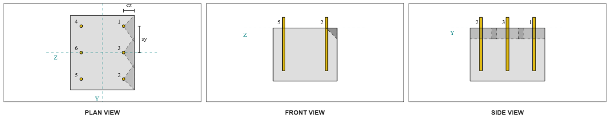
小切手 #2: vyせん断によるコンクリートブレイクアウト容量を計算します
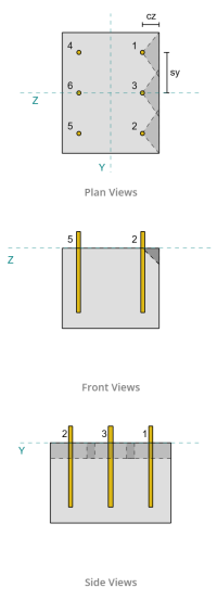
垂直エッジ容量:
レイアウトから, アンカー 1 そして 4 端に最も近く、持っています 最短のCA1距離. これらのCA1値を使用して、故障コーンを投影します, ソフトウェアは、これらのアンカーをとして識別しました シングルアンカー, 投影されたコーンは重複していないためです. サポートも狭いメンバーではないと判断されました, したがって、CA1距離は変更なしで直接使用されます.
せん断力がすべてのアンカーに分散されると仮定していることを思い出してください。. の計算 Vせん断荷重 それぞれの単一アンカーに適用されるのは、:
\( V_{ファペルプ} = frac{v_y}{なし} = frac{2\,\テキスト{キップ}}{6} = 0.33333,text{キップ} \)
考えてみましょう アンカー 1. 単一アンカーの最大投影面積は、次のように計算されます。 ACI 318-19 Eq. 17.7.2.1.3.
\( A_{Vco} = 4.5 (c_{A1、S1})^2 = 4.5 \回 (2\,\テキスト{に})^2 = 18,text{に}^ 2 \)
実際の投影面積は、投影された破損円錐の幅と高さから決定されます。.
\( b_{VC} = min(c_{左,s1},\, 1.5c_{A1、S1}) + \分(c_{正しい,s1},\, 1.5c_{A1、S1}) \)
\( b_{VC} = min(10\,\テキスト{に},\, 1.5 \2 倍,テキスト{に}) + \分(2\,\テキスト{に},\, 1.5 \2 倍,テキスト{に}) = 5,テキスト{に} \)
\( それを計算するために{VC} = min(1.5c_{A1、S1},\, t_{コンク}) = min(1.5 \2 倍,テキスト{に},\, 10\,\テキスト{に}) = 3,テキスト{に} \)
\( A_{VC} = b_{VC} それを計算するために{VC} = 5,テキスト{に} \3 倍,テキスト{に} = 15,テキスト{に}^ 2 \)
次のステップは、使用することです 式 17.7.2.2.1a および 17.7.2.2.1b 単一アンカーの基本的なブレークアウト強度を計算するには. 統治能力は小さい方の値として扱われます.
\( V_{b1} = 7 \左( \フラク{\分(の,\, 8D_A)}{D_A} \正しい)^{0.2} \平方根{\フラク{D_A}{\テキスト{に}}} \lambda_a sqrt{\フラク{f’_c}{\テキスト{psi}}} \左( \フラク{c_{A1、S1}}{\テキスト{に}} \正しい)^{1.5} \,\テキスト{lbf} \)
\( V_{b1} = 7 \倍左( \フラク{\分(8\,\テキスト{に},\, 8 \0.5 倍,text{に})}{0.5\,\テキスト{に}} \正しい)^{0.2} \回 sqrt{\フラク{0.5\,\テキスト{に}}{1\,\テキスト{に}}} \回 1 \回 sqrt{\フラク{3\,\テキスト{KSI}}{0.001\,\テキスト{KSI}}} \倍左( \フラク{2\,\テキスト{に}}{1\,\テキスト{に}} \正しい)^{1.5} \0.001 倍,text{キップ} \)
\( V_{b1} = 1.1623,text{キップ} \)
\( V_{b2} = 9 \lambda_a sqrt{\フラク{f’_c}{\テキスト{psi}}} \左( \フラク{c_{A1、S1}}{\テキスト{に}} \正しい)^{1.5} \,\テキスト{lbf} \)
\( V_{b2} = 9 \回 1 \回 sqrt{\フラク{3\,\テキスト{KSI}}{0.001\,\テキスト{KSI}}} \倍左( \フラク{2\,\テキスト{に}}{1\,\テキスト{に}} \正しい)^{1.5} \0.001 倍,text{キップ} = 1.3943,text{キップ} \)
\( V_b = 分(V_{b1},\, V_{b2}) = min(1.1623\,\テキスト{キップ},\, 1.3943\,\テキスト{キップ}) = 1.1623,text{キップ} \)
次, の ブレイクアウト容量パラメータ 決まっている. の ブレイクアウトエッジ効果係数 に従って計算されます ACI 318-19 句 17.7.2.4, そしてその 厚さ係数 に従って計算されます 句 17.7.2.6.1.
\( \psi_{ed,V } = min 左(1.0,\, 0.7 + 0.3 \左( \フラク{c_{A2、S1}}{1.5c_{A1、S1}} \正しい) \正しい) = min 左(1,\, 0.7 + 0.3 \倍左( \フラク{2\,\テキスト{に}}{1.5 \2 倍,テキスト{に}} \正しい) \正しい) = 0.9 \)
\( \psi_{h,V } = max 左( \平方根{ \フラク{1.5c_{A1、S1}}{t_{コンク}} },\, 1.0 \正しい) = max 左( \平方根{ \フラク{1.5 \2 倍,テキスト{に}}{10\,\テキスト{に}} },\, 1 \正しい) = 1 \)
最後に, ACI 318-19 句 17.7.2.1(a) せん断中の単一アンカーのコンクリートブレイクアウト容量を決定するために使用されます. 垂直方向のvyせん断の計算能力は 0.69 キップ.
\( \ファイV_{cb perp} = phi 左( \フラク{A_{VC}}{A_{Vco}} \正しい) \psi_{ed,V } \psi_{c,V } \psi_{h,V } V_B \)
\( \ファイV_{cb perp} = 0.65 \倍左( \フラク{15\,\テキスト{に}^ 2}{18\,\テキスト{に}^ 2} \正しい) \回 0.86 \回 1 \回 1 \Times 1.1623 、 Text{キップ} = 0.56661 、 text{キップ} \)
の計算容量 vy shear の中に 垂直 方向はです 0.56 キップ.
平行エッジ容量:
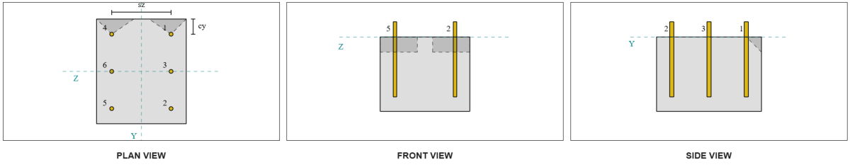
このシナリオでは、負荷に平行なエッジに沿った障害も可能です, だから 平行エッジのコンクリートブレイクアウト容量 決定する必要があります. 考慮されるアンカーまたはアンカーグループは、平行エッジと整列したものです. したがって, の CA1 エッジ距離は、Z方向に沿ってアンカーからエッジまで測定されます. 以下の図に基づいています, 故障コーンの投影が重複しています; したがって, アンカーはグループとして扱われます.
場合 1:
場合 2:
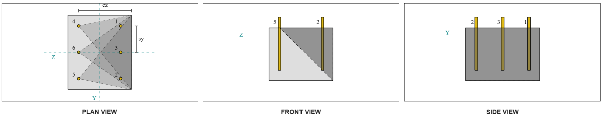
参照します ACI 318-19 図. R17.7.2.1b アンカー グループを評価するときに使用されるさまざまなケースについて. このベースプレートのデザインでは, 溶接プレートワッシャー 具体的に使われている. したがって, のみ 場合 2 チェックされています.
Caseのアンカーグループに必要な荷重 2 として取られます 総せん断荷重.
\( V_{ファパラレル,ケース2} = V_y = 2,text{キップ} \)
ケースの容量計算にあたって 2 失敗, 考慮されるアンカーは リアアンカー. 結果として, ca1 エッジ距離は、後部アンカー グループから破損エッジまで測定されます。.
この ca1 距離とエッジ方向を使用すると、, サポートがナローメンバーとしての資格があるかどうかを検証する必要があります. 続く ACI 318-19 句 17.7.2.1.2, SkyCiv ベース プレート ソフトウェアはサポートを次のように識別しました。 狭い. したがって, の 修正されたca1距離 使用されている, と計算される 6.667 に.
垂直の場合と同じ手順に従います。: を計算する 予想される故障領域, の 基本的なシングルアンカーブレークアウト強度, そしてその ブレイクアウトパラメータ. 各ステップの計算値を以下に示します.
\( A_{Vco} = 4.5 (c_{「A1、G2})^2 = 4.5 \回 (6.6667\,\テキスト{に})^2 = 200 、 text{に}^ 2 \)
\( A_{VC} = b_{VC} それを計算するために{VC} = 14 、 text{に} \時間10 、テキスト{に} = 140 、 text{に}^ 2 \)
\( V_{b1} = 7.0733 、テキスト{キップ} \)
\( V_{b2} = 8.4853 、 text{キップ} \)
\( V_b = 分(V_{b1},\, V_{b2}) = min(7.0733\,\テキスト{キップ},\, 8.4853\,\テキスト{キップ}) = 7.0733 、テキスト{キップ} \)
\( \psi_{ed,V } = 1.0 \)
\( \psi_{h,V } = 1.0 \)
平行エッジ容量の方程式は、垂直エッジ容量とは異なります. ACI 318-19 句 17.7.2.1(c) 適用されます, ブレークアウト方程式はどこにありますか 掛ける 2.
\( \ファイV_{cbg 並列} = 2 \Phi 左( \フラク{A_{VC}}{A_{Vco}} \正しい) \psi_{ed,V } \psi_{c,V } \psi_{h,V } V_B \)
\( \ファイV_{cbg 並列} = 2 \回 0.65 \倍左( \フラク{140\,\テキスト{に}^ 2}{200\テキスト{に}^ 2} \正しい) \回 1 \回 1 \回 1 \Times 7.0733 、 Text{キップ} = 6.4367 、 text{キップ} \)
の計算容量 vy shear の中に 平行 方向はです 6.43 キップ.
ここで、垂直障害と並列障害を個別に評価します.
- 垂直エッジの故障のため, 以来 0.33 キップ < 0.56 キップ, 設計コンクリートせん断ブレークアウト容量はです 十分な.
- 平行なエッジ障害の場合, 以来 2 キップ < 6.43 キップ, 設計コンクリートせん断ブレークアウト容量はです 十分な.
小切手 #3: VZせん断によるコンクリートブレイクアウト容量を計算します
ベースプレートにも適用されます VZせん断, したがって、故障エッジは垂直でVZせん断に平行にチェックする必要があります. 同じアプローチを使用します, 垂直容量と平行容量が計算されます 2.45 キップ そして 1.26 キップ, それぞれ.
垂直エッジ:
平行エッジ:
これらの容量は、必要な強度と比較されます.
- 垂直エッジの故障のため, 以来 2 キップ < 2.45 キップ, コンクリートせん断ブレークアウト容量はです 十分な.
- 平行なエッジ障害の場合, 以来 0.33 キップ < 1.26 キップ, コンクリートせん断ブレークアウト容量はです 十分な.
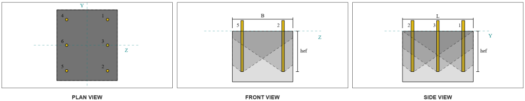
小切手 #4: コンクリートのプリアウト容量を計算します
の プリアウト障害のためのコンクリートコーン 引張ブレイクアウトチェックで使用されているコーンと同じです. せん断格子容量を計算します, 単一のアンカーまたはアンカーグループの公称引張ブレイクアウト強度を最初に決定する必要があります. 引張ブレイクアウトチェックの詳細な計算は、 緊張負荷のためのSkyCIVデザインの例.
せん断格子のアンカーグループの決定は、せん断ブレークアウトのアンカーグループの決定とは異なることに注意することが重要です. したがって, デザインのアンカーは、それらが 行為 限られた亀裂幅と同様に グループ またはとして シングルアンカー せん断格納障害に対して. サポートの分類として 狭いセクション も検証する必要があり、使用したのと同じ条件に従う必要があります。 緊張のブレイクアウト.
SkyCiv の計算による, の 公称引張破断強さ アンカーグループの 12.772 キップ. プライアウト係数を使用すると、 kcp=2, 設計上のプラアウト容量は:
\( \ファイV_{日用品} = hyk_{cp} N_{cbg} = 0.65 \回 2 \回 12.772 \,\テキスト{キップ} = 16.604,text{キップ} \)
必要な強度は、 加えられたせん断荷重の結果. すべてのアンカーは単一のグループに属しているため、, 結果として生じるせん断の合計がグループに割り当てられます。.
\( V_{する} = sqrt{(v_y)^ 2 + (V_Z)^ 2} = sqrt{(2\,\テキスト{キップ})^ 2 + (2\,\テキスト{キップ})^ 2} = 2.8284,text{キップ} \)
\( V_{する} = left( \フラク{V_{する}}{なし} \正しい) n_{a,G1} = left( \フラク{2.8284\,\テキスト{キップ}}{6} \正しい) \回 6 = 2.8284,text{キップ} \)
総せん断荷重がアンカーグループの耐力より小さいため, 2.82 キップ < 18.976 キップ, 設計上のプラアウト容量は 十分な.
小切手 #5: アンカーロッドのせん断耐力を計算する
この設計例でのことを思い出してください。, せん断はすべてのアンカーに分散されます. したがって、アンカーあたりのせん断荷重の合計は、Vy 荷重の分担と Vz 荷重の分担の結果となります。.
\( v_{する,そして} = frac{v_y}{なし} = frac{2\,\テキスト{キップ}}{6} = 0.33333,text{キップ} \)
\( v_{する,と} = frac{V_Z}{なし} = frac{2\,\テキスト{キップ}}{6} = 0.33333,text{キップ} \)
\( V_{する} = sqrt{(v_{する,そして})^ 2 + (v_{する,と})^ 2} \)
\( V_{する} = sqrt{(0.33333\,\テキスト{キップ})^ 2 + (0.33333\,\テキスト{キップ})^ 2} = 0.4714,text{キップ} \)
これにより、 アンカーロッドにかかるせん断応力 なので:
\( f_v = frac{V_{する}}{A_{ロッド}} = frac{0.4714\,\テキスト{キップ}}{0.19635\,\テキスト{に}^ 2} = 2.4008,text{KSI} \)
プレートワッシャーが入っているので, AN 偏心せん断荷重 アンカーロッドに誘導される. 偏心は、コンクリートサポートの上部からプレートワッシャーの中心までの距離の半分として計算されます。, ベースプレートの厚さを考慮して. 参照してください AISC 設計ガイド 1, 3第 3 版セクション 4.3.3.
\( e = 0.5 \左( \フラク{t_{パスワード}}{2} + t_{血圧} \正しい) = 0.5 \倍左( \フラク{0.25\,\テキスト{に}}{2} + 0.75\,\テキスト{に} \正しい) = 0.4375,text{に} \)
偏心せん断によるモーメントは次のように表されます。 アンカーロッドの軸応力. 断面係数の使用, このモーメントによる軸応力は次のように計算されます。:
\( Z_{ロッド} = frac{\パイ}{32} (D_A)^3 = frac{\パイ}{32} \回 (0.5\,\テキスト{に})^3 = 0.012272,text{に}他のいくつかの例は \)
\( f_t = frac{V_{する} e}{Z_{ロッド}} = frac{0.4714\,\テキスト{キップ} \0.4375 倍,text{に}}{0.012272\,\テキスト{に}他のいくつかの例は} = 16.806,text{KSI} \)
ACIアンカーロッドせん断耐力:
続く ACI 318-19 句 17.7.1, その後、設計強度が決定されます. あ 0.8 削減率 の存在により適用される グラウトパッド. したがって、設計能力は次のようになります。:
\( \ファイV_{に,ここに} = 0.8 \ファイ 0.6 A_{知っている,v} f_{uta} = 0.8 \回 0.65 \回 0.6 \0.1419text の倍{に}^2 times 90テキスト{KSI} = 3.9845テキスト{キップ} \)
代替として, の SkyCIVベースプレートソフトウェア を許可します 0.8 無効になる簡素化, 計算で実際のグラウトパッドの厚さを使用します. この場合, 総偏心にはグラウトパッドが含まれます, そして、せん断強度と軸方向の強度は、AISCの規定に従って決定されます.
AISCアンカーロッドせん断容量:
最初, の 公称せん断および引張応力 A325ロッドに対して決定されます.
\( F_{NV} = 0.45 F_{あなた,anc} = 0.45 \回 120\ \テキスト{KSI} = 54\ \テキスト{KSI} \)
\( F_{nt} = 0.75 F_{あなた,anc} = 0.75 \回 120\ \テキスト{KSI} = 90\ \テキスト{KSI} \)
AISCメソッドが使用します AISC 360-22 Eq. J3-3a, 軸応力の効果を含めるように表現される場合があります. これは次のように実行されます.
\( f’_{NV} = min left( 1.3 F_{NV} – \左( \フラク{F_{NV}}{\phi f_{nt}} \正しい) f_t,\; F_{NV} \正しい) \)
\( f’_{NV} = min left( 1.3 \回 54\ \テキスト{KSI} – \左( \フラク{54\ \テキスト{KSI}}{0.75 \回 90\ \テキスト{KSI}} \正しい) \回 16.806\ \テキスト{KSI},\; 54\ \テキスト{KSI} \正しい) = 54\ \テキスト{KSI} \)
AISCメソッドからの設計せん断容量は、:
\( \ファイR_{ん,\Mathrm{AISC}} = phi f’_{NV} A_{ロッド} = 0.75 \回 54\ \テキスト{KSI} \回 0.19635\ \テキスト{に}^2 = 7.9522\)
両方の方法がカバーされていることを確認します, 統治能力は2つのうちの少ないものとしてとられます, それは 3.98 キップ.
\( \phi v_n = min 左( \ファイV_{に,ここに},\; \ファイR_{ん,\Mathrm{AISC}} \正しい) = min (3.9845\ \テキスト{キップ},\; 7.9522\ \テキスト{キップ}) = 3.9845\ \テキスト{キップ} \)
アンカーロッドあたりのせん断荷重は、せん断の支配アンカーロッド容量よりも少ないため, 0.47 キップ < 3.98 キップ, デザインアンカーロッドせん断容量はです 十分な.
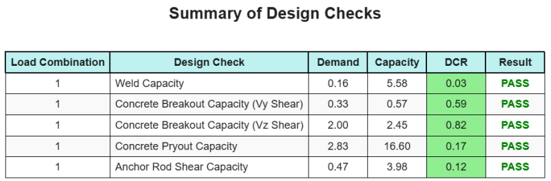
設計の概要
の SkyCYVベースプレート設計ソフトウェア このデザインの例の段階的な計算レポートを自動的に生成できます. また、実行されたチェックとその結果の比率の概要も提供します, 情報を一目で理解しやすくします. 以下はサンプルの概要表です, レポートに含まれています.
SkyCIVサンプルレポート
SkyCiv ベース プレート設計レポートから期待できる詳細レベルと明瞭さのレベルを確認してください。. The report includes all key design checks, 方程式, 結果は明確で読みやすい形式で表示されます. It is fully compliant with design standards. SkyCiv ベース プレート カリキュレーターを使用して生成されたサンプル レポートを表示するには、以下をクリックしてください。.
ベースプレートソフトウェアを購入します
他のSkyCIVモジュールなしで、ベースプレートデザインモジュールのフルバージョンを単独で購入する. これにより、ベースプレートデザインの完全な結果が得られます, 詳細なレポートとその他の機能を含む.