動線は何のためにあるのか?
モデルのセクションとノードの計算値のインフルエンス ラインを取得したい場合, まず、プリプロセッサで単位荷重の移動パスを定義する必要があります。. Traffic Lines ツールを使用すると、これを行うことができます.
使い方
Traffic Linesパラメータウィンドウを開くボタンは、Moving Loadsセクションの左側インターフェースパネルにあります。.
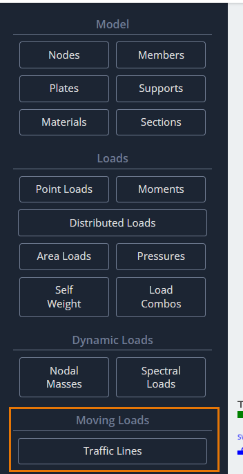
このボタンをクリックした後, [トラフィック ライン] ダイアログ ボックスがモデリング領域に表示され、パラメータを定義します。.
![SkyCiv の [交通線] ダイアログ ボックス, ポイントまたはメンバーによってラインを定義するオプションを表示.](https://skyciv.com/wp-content/uploads/2025/10/skyciv-traffic-lines-dialog-box.png)
動線ID
モデルで定義されているすべてのトラフィック ラインのリスト. 選択できます, 編集, 不要になった場合は削除します.
動線は空間の線です. この線は真っ直ぐである必要はありません. このような線を定義するには 2 つの方法があります. 最初の方法では、モデル内の既存の点を使用するか、ラインの頂点に直接座標入力を使用します。.
点を使用した動線の定義
ポイント
動線が直線の場合, 2 つの点を定義するだけで十分です: 始まりと終わり.
- 点で定義するには, この形式でノード ID を指定します:
1;4 - 座標で点を定義する場合, この形式で入力する必要があります:
0,2.3,0; 210,2.3,0
荷重を適用するメンバー ID
研究対象の因子の値を取得するには, 一連の静的解析を実行する必要がある. プログラムは、各静的荷重のどこに単位力を配置するかを知る必要があります。. これをする, メンバーのセットを定義する必要があります.
これらの部材と動線との交差/重ね合わせ点に単位力が適用され、荷重ケースが作成されます。. このプロセスは、分析の実行時に自動的に実行されます。.
交差点が多ければ多いほど, より正確な影響線が得られます. しかしながら, 交差が多すぎると計算時間が長くなります. 妥当な数字を選択してください.
- メンバーのリストは次の形式で入力されます。:
1, 2, 3, 4 - 使用する “自動入力”. リストは自動的に定義され、手動で編集できます。.
メンバーを使用した動線の定義
![SkyCiv の [交通線] ダイアログ ボックス, オフセットおよび参照ノード ID のオプションを含む [メンバー] タブを表示.](https://skyciv.com/wp-content/uploads/2025/10/skyciv-traffic-lines-dialog-members-tab.png)
あるいは, メンバーのチェーンを使用して動線パスを定義できます. このアプローチは、意図したパスが曲線であり、構造部材の曲率に従う場合に特に役立ちます。 (橋桁のような, 等).
これをする, パスのメンバーをリストの形式で入力します。: 1;2;7;4;5;12… または 1-25 チェーン内のメンバーが連続している場合.
オフセット
このフィールドは、指定されたメンバーのチェーンからのオフセット距離を定義します。. したがって, 動線がメンバー チェーンの形状に従う必要があるが、その正確な位置は必要ない場合に便利です。.
参照ノードID
ここに, 指定したメンバーチェーンからのトラフィックラインのオフセットの方向を定義するノードのIDを指定します。.
最後に, すべてのパラメータを定義した後, 繰り返し間の距離 適用する 動線をリストに追加するには.
影響線
動線を定義したモデルで解析を実行した後, 結果を影響線として分析できます. これをする, を見つけなければなりません 影響線 ポストプロセッサの左側のインターフェースパネルにあるボタン.
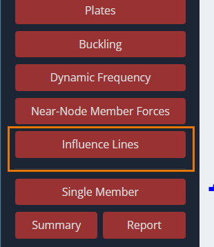
このボタンをクリックした後, の 影響線 パラメータを定義するためのダイアログ ボックスがモデリング領域に表示されます。.
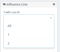
![SkyCiv の [インフルエンス ライン] ダイアログ ボックス, トラフィック ライン ID のフィールドを表示, 結果, 成分, メンバーがいます, と会員ID](https://skyciv.com/wp-content/uploads/2025/10/skyciv-influence-line-dialog-box.png)
動線ID
このドロップダウン リストでは, 影響線を構築する動線の ID を選択できます。. を選択して、すべての動線の影響線を構築することもできます。 “すべて”.
結果
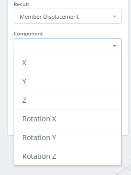
このリストでは、影響線を構築するための結果のタイプを選択できます。.
成分
このリストには、サポートされているノードでの反応の結果の値が表示されます。, または部材セクションの力と変位. このリストの内容は、 “結果” リスト.
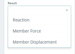
もし “結果” に設定されています 反応, リストは次のようになります:
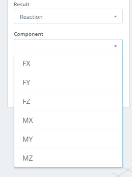
もし “結果” に設定されています メンバーフォース, リストは次のようになります:
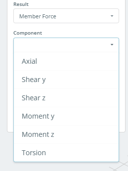
もし “結果” に設定されています メンバーの移動, リストは次のようになります:
メンバーがいます
もし “結果” に設定されています 反応, インフルエンス ラインが構築されるサポート対象ノードの ID を指定する必要があります。.
メンバーID
もし “結果” に設定されています メンバーフォース または メンバーの移動, インフルエンス ラインを構築するメンバー ID を指定する必要があります.
メンバーに沿った位置 (0-100%)
このフィールドは、影響線が構築される部材上のセクションの位置を指定します。. セクションの座標は、部材の全長に対するパーセンテージとして設定されます。, メンバーの開始から測定.
をクリックした後、 適用する ボタン, 影響線がモデル上にグラフィカルにプロットされます.
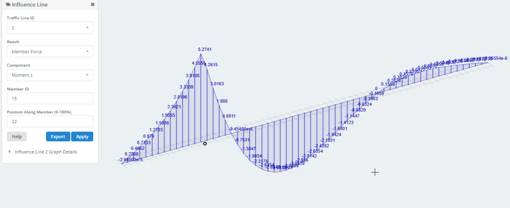
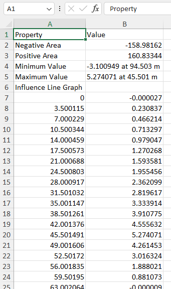
の 書き出す ボタンを使用すると、影響線データを Excel ファイルとしてコンピュータに保存できます。.
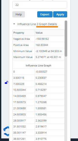
をクリックしてこの情報を取得することもできます。 グラフの詳細.
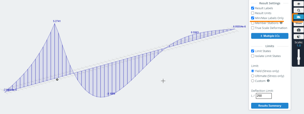
グラフ上に最小値/最大値のみを表示するには, 右側のメニューで次の設定を使用します: