ENを使用したベースプレートデザインの例 1993-1-8:2005, に 1993-1-1:2005, に 1992-1-1:2004, およびEN 1992-4:2018.
問題ステートメント
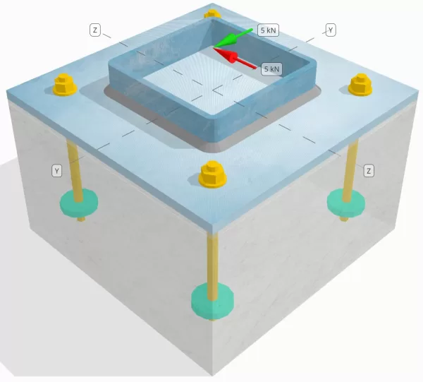
設計された柱とベース プレートの接続が十分な接続であるかどうかを判断します。 Vy=5-kN そして Vz=5-kN せん断荷重.
指定されたデータ
カラム:
列セクション: SHS 180x180x8
列エリア: 5440 んん2
列素材: S235
ベースプレート:
ベースプレートの寸法: 350 mm x 350 んん
ベースプレートの厚さ: 12 んん
ベースプレート材料: S235
グラウト:
グラウトの厚さ: 6 んん
グラウト材: ≥ 30 MPa
コンクリート:
具体的な寸法: 350 mm x 350 んん
コンクリートの厚さ: 350 んん
コンクリート材料: C25/30
ひび割れまたは破損していません: 割れた
アンカー:
アンカーの直径: 12 んん
効果的な埋め込み長: 150 んん
埋め込まれたプレートの直径: 60 んん
埋め込まれたプレートの厚さ: 10 んん
アンカー素材: 8.8
その他の情報:
- カウンターサンクアンカー以外.
- カットスレッドを備えたアンカー.
- アンカー鋼のせん断破壊に関する K7 係数: 1.0
- ファスナーの拘束度: 拘束なし
溶接:
溶接タイプ: すみ肉溶接
溶接脚のサイズ: 8んん
フィラー金属分類: E35
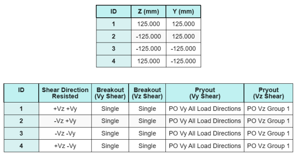
アンカーデータ (から SkyCIV計算機):
SkyCiv 無料ツールでモデルを作成する
無料のオンライン ツールを使用して、上記のベース プレート設計を今すぐモデル化してください。! サインアップは必要ありません.
定義
ロードパス:
の SkyCYVベースプレート設計ソフトウェア 続く に 1992-4:2018 アンカーロッド設計用. 柱にかかるせん断荷重は、溶接部を介してベースプレートに伝達され、アンカーロッドを介して支持コンクリートに伝達されます。. この例では、摩擦ラグとせん断ラグは考慮されていません。, これらのメカニズムは現在のソフトウェアではサポートされていないため、.
アンカーグループ:
このソフトウェアには、どのアンカーが評価用のアンカー グループの一部であるかを識別する直感的な機能が含まれています。 コンクリートせん断ブレークアウト そして コンクリートせん断格子 障害.
アン アンカーグループ 投影された抵抗領域が重複する2つ以上のアンカーとして定義されます. この場合, アンカーは一緒に行動します, そして、それらの組み合わせ抵抗は、グループの適用された負荷に対してチェックされます.
あ シングルアンカー 投影抵抗領域が他のものと重複しないアンカーとして定義されます. この場合, アンカーは単独で作用します, そして、そのアンカーに加えられたせん断力は、個々の抵抗に対して直接チェックされます.
この区別により、せん断関連の故障モードを評価する際に、ソフトウェアがグループの動作と個々のアンカーパフォーマンスの両方をキャプチャできます。.
段階的な計算
小切手 #1: 溶接容量を計算します
私たちは、 Vz せん断荷重は、 上下の溶接, ながら あなた せん断荷重はもっぱら抵抗されます。 左右の溶接部分.
の溶接能力を決定するには、 上下の溶接, まずそれらを計算します 溶接部の全長.
\(
L_{w,top\&底} = 2 \左(=最も近いサポートの面までのせん断が考慮されているセクションの距離{col} – 2t_{col} – 2r_{col}\正しい)
= 2 \倍左(180 \,\テキスト{んん} – 2 \回 8 \,\テキスト{んん} – 2 \回 4 \,\テキスト{んん}\正しい)
= 312 \,\テキスト{んん}
\)
次, を計算します 溶接部の応力.
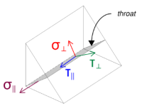
適用される Vz せん断は溶接軸と平行に作用することに注意してください。, 他に力が存在しない状態で. これは、垂直応力をゼロとして扱うことができることを意味します。, そして唯一の 平行方向のせん断応力 計算する必要がある.
\(
\シグマ_{\perp} = frac{N}{(L_{w,top\&底})\,a\sqrt{2}}
= frac{0 \,\テキスト{kN}}{(312 \,\テキスト{んん}) \回 5.657 \,\テキスト{んん} \回 sqrt{2}}
= 0
\)
\(
\君の_{\perp} = frac{0}{(L_{w,top\&底})\,a\sqrt{2}}
= frac{0 \,\テキスト{kN}}{(312 \,\テキスト{んん}) \回 5.657 \,\テキスト{んん} \回 sqrt{2}}
= 0
\)
\(
\君の_{\平行} = frac{V_{と}}{(L_{w,top\&底})\,a}
= frac{5 \,\テキスト{kN}}{(312 \,\テキスト{んん}) \回 5.657 \,\テキスト{んん}}
= 2.8329 \,\テキスト{MPa}
\)
使用する に 1993-1-8:2005, Eq. 4.1, 設計溶接応力は方向性法を使用して取得されます。.
\(
F_{w,エド1} = sqrt{ (\シグマ_{\perp})^ 2 + 3 \左( (\君の_{\perp})^ 2 + (\君の_{\平行})^2 右) }
= sqrt{ (0)^ 2 + 3 \倍左( (0)^ 2 + (2.8329 \,\テキスト{MPa})^2 右) }
= 4.9067 \,\テキスト{MPa}
\)
加えて, 母材チェックの設計法線応力, あたり に 1993-1-8:2005, Eq. 4.1, ゼロとみなされます, 以来 通常のストレスがない 存在します.
\(
F_{w,エド2} = シグマ_{\perp} = 0
\)
今, を評価しましょう 左右の溶接部分. 上下の溶接と同様に, まず計算します 総溶接長.
\(
L_{w,left\&正しい} = 2 \左(d_{col} – 2t_{col} – 2r_{col}\正しい)
= 2 \倍左(180 \,\テキスト{んん} – 2 \回 8 \,\テキスト{んん} – 2 \回 4 \,\テキスト{んん}\正しい)
= 312 \,\テキスト{んん}
\)
次に、の成分を計算します。 溶接応力.
\(
\シグマ_{\perp} = frac{N}{(L_{w,left\&正しい})\,a\sqrt{2}}
= frac{0 \,\テキスト{kN}}{(312 \,\テキスト{んん}) \回 5.657 \,\テキスト{んん} \回 sqrt{2}}
= 0
\)
\(
\君の_{\perp} = frac{0}{(L_{w,left\&正しい})\,a\sqrt{2}}
= frac{0 \,\テキスト{kN}}{(312 \,\テキスト{んん}) \回 5.657 \,\テキスト{んん} \回 sqrt{2}}
= 0
\)
\(
\君の_{\平行} = frac{v_y}{(L_{w,left\&正しい})\,a}
= frac{5 \,\テキスト{kN}}{(312 \,\テキスト{んん}) \回 5.657 \,\テキスト{んん}}
= 2.8329 \,\テキスト{MPa}
\)
使用する に 1993-1-8:2005, Eq. 4.1, 母材チェックのための設計溶接応力と設計垂直応力の両方を決定します.
\(
F_{w,エド1} = sqrt{ \左( \シグマ_{\perp} \正しい)^ 2 + 3 \左( \左( \君の_{\perp} \正しい)^ 2 + \左( \君の_{\平行} \正しい)^2 右) }
\)
\(
F_{w,エド1} = sqrt{ \左( 0 \正しい)^ 2 + 3 \倍左( \左( 0 \正しい)^ 2 + \左( 2.8329 \,\テキスト{MPa} \正しい)^2 右) }
\)
\(
F_{w,エド1} = 4.9067 \,\テキスト{MPa}
\)
次のステップは、 溶接応力の管理 上下の溶接部と左右の溶接部の間. 溶接の長さが等しく、加えられる荷重も同じ大きさであるため、, 結果として得られる溶接応力は等しい.
\(
F_{w,エド1} = \max(F_{w,エド1}, \, F_{w,エド1})
= \max(4.9067 \,\テキスト{MPa}, \, 4.9067 \,\テキスト{MPa})
= 4.9067 \,\テキスト{MPa}
\)
母材の応力はゼロのままです.
\(
F_{w,エド2} = \max(F_{w,エド2}, \, F_{w,エド2}) = \max(0, \, 0) = 0
\)
今, 溶接能力を計算します. 最初, の抵抗 すみ肉溶接 計算される. その後, の抵抗 卑金属 決まっている. ENの使用 1993-1-8:2005, Eq. 4.1, the capacities are calculated as follows:
\(
F_{w,RD1} = frac{f_u}{\beta_w \left(\それを計算するために{M2,weld}\正しい)}
= frac{360 \,\テキスト{MPa}}{0.8 \回 (1.25)}
= 360 \,\テキスト{MPa}
\)
\(
F_{w,Rd2} = frac{0.9 f_u}{\それを計算するために{M2,weld}}
= frac{0.9 \回 360 \,\テキスト{MPa}}{1.25}
= 259.2 \,\テキスト{MPa}
\)
最後に, we compare the weld stresses with the weld capacities, and the base metal stresses with the base metal capacities.
以来 4.9067 MPa < 360 MPa そして 0 MPa < 259.2 MPa, the capacity of the welded connection is 十分な.
小切手 #2: vyせん断によるコンクリートブレイクアウト容量を計算します
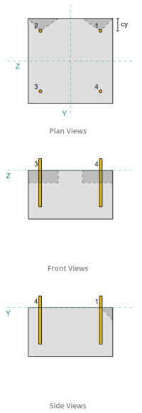
Following the provisions of に 1992-4:2018, the edge perpendicular to the applied load is assessed for shear breakout failure. Only the anchors nearest to this edge are considered engaged, while the remaining anchors are assumed not to resist shear.
These edge anchors must have a concrete edge distance greater than the larger of 10·hef and 60·d, どこ 持っている is the embedment length and d is the anchor diameter. If this condition is not met, the thickness of the base plate must be less than 0.25·hef.
If the requirements in に 1992-4:2018, 句 7.2.2.5(1), are not satisfied, the SkyCiv software cannot proceed with the design checks, and the user is advised to refer to other relevant standards.
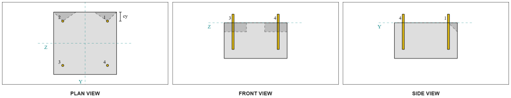
From the SkyCiv software results, the edge anchors act as シングルアンカー, since their projected areas do not overlap. この計算のために, アンカー 1 will be considered.
To calculate the portion of the Vy shear load carried by Anchor 1, the total Vy shear is distributed among the anchors nearest to the edge. これにより、 perpendicular force on Anchor 1.
\(
V_{\perp} = frac{v_y}{n_{a,s}}
= frac{5 \,\テキスト{kN}}{2}
= 2.5 \,\テキスト{kN}
\)
のために parallel force, it is assumed that all anchors resist the load equally. したがって, the parallel component of the load is calculated as:
\(
V_{\平行} = frac{V_Z}{n_{anc}}
= frac{5 \,\テキスト{kN}}{4}
= 1.25 \,\テキスト{kN}
\)
の 総せん断荷重 on Anchor 1 is therefore:
\(
V_{エド} = sqrt{ \左( V_{\perp} \正しい)^ 2 + \左( V_{\平行} \正しい)^ 2 }
\)
\(
V_{エド} = sqrt{ \左( 2.5 \,\テキスト{kN} \正しい)^ 2 + \左( 1.25 \,\テキスト{kN} \正しい)^ 2 } = 2.7951 \,\テキスト{kN}
\)
The first part of the capacity calculation is to determine the alpha and beta factors. 使用します に 1992-4:2018, 句 7.2.2.5, to set the lf dimension, そして 方程式 7.42 そして 7.43 to determine the factors.
\(
l_f = \min(h_{ef}, \, 12d_{anc})
= min(150 \,\テキスト{んん}, \, 12 \回 12 \,\テキスト{んん})
= 144 \,\テキスト{んん}
\)
\(
\alpha = 0.1 \左(\フラク{l_f}{c_{1,s1}}\正しい)^{0.5}
= 0.1 \倍左(\フラク{144 \,\テキスト{んん}}{50 \,\テキスト{んん}}\正しい)^{0.5}
= 0.16971
\)
\(
\beta = 0.1 \左(\フラク{d_{anc}}{c_{1,s1}}\正しい)^{0.2}
= 0.1 \倍左(\フラク{12 \,\テキスト{んん}}{50 \,\テキスト{んん}}\正しい)^{0.2}
= 0.07517
\)
The next step is to calculate the initial value of the characteristic resistance of the fastener. 使用する に 1992-4:2018, 方程式 7.41, the value is:
\(
V ^{0}_{Rk,c} = k_9 \left( \フラク{d_{anc}}{\テキスト{んん}} \正しい)^{\アルファ}
\左( \フラク{l_f}{\テキスト{んん}} \正しい)^{\ベータ}
\平方根{ \フラク{f_{ck}}{\テキスト{MPa}} }
\左( \フラク{c_{1,s1}}{\テキスト{んん}} \正しい)^{1.5} N
\)
\(
V ^{0}_{Rk,c} = 1.7 \倍左( \フラク{12 \,\テキスト{んん}}{1 \,\テキスト{んん}} \正しい)^{0.16971}
\倍左( \フラク{144 \,\テキスト{んん}}{1 \,\テキスト{んん}} \正しい)^{0.07517}
\回 sqrt{ \フラク{20 \,\テキスト{MPa}}{1 \,\テキスト{MPa}} }
\倍左( \フラク{50 \,\テキスト{んん}}{1 \,\テキスト{んん}} \正しい)^{1.5}
\回 0.001 \,\テキスト{kN}
\)
\(
V ^{0}_{Rk,c} = 5.954 \,\テキスト{kN}
\)
その後, 計算します 参照投影エリア of a single anchor, 以下 に 1992-4:2018, 方程式 7.44.
\(
A_{c,V }^{0} = 4.5 \左( c_{1,s1} \正しい)^ 2
= 4.5 \倍左( 50 \,\テキスト{んん} \正しい)^ 2
= 11250 \,\テキスト{んん}^ 2
\)
その後, 計算します 実際の投影エリア of Anchor 1.
\(
b_{c,V } = min(c_{左,s1}, \, 1.5c_{1,s1}) + \分(c_{正しい,s1}, \, 1.5c_{1,s1})
\)
\(
b_{c,V } = min(300 \,\テキスト{んん}, \, 1.5 \回 50 \,\テキスト{んん}) + \分(50 \,\テキスト{んん}, \, 1.5 \回 50 \,\テキスト{んん}) = 125 \,\テキスト{んん}
\)
\(
それを計算するために{c,V } = min(1.5c_{1,s1}, \, t_{コンク}) = min(1.5 \回 50 \,\テキスト{んん}, \, 200 \,\テキスト{んん}) = 75 \,\テキスト{んん}
\)
\(
A_{c,V } の場合、ベースの下部から壁の高さの半分{c,V } b_{c,V } = 75 \,\テキスト{んん} \回 125 \,\テキスト{んん} = 9375 \,\テキスト{んん}^ 2
\)
せん断ブレークアウトのパラメータを計算する必要もあります. 使用します に 1992-4:2018, 方程式 7.4, を説明する係数を取得するには 応力分布の乱れ, 方程式 7.46 を説明する要因については、 部材の厚さ, そして 方程式 7.48 を説明する要因については、 エッジに傾斜したせん断荷重の影響. これらは次のように計算されます:
\(
\psi_{s,V } = min left( 0.7 + 0.3 \左( \フラク{c_{2,s1}}{1.5c_{1,s1}} \正しい), \, 1.0 \正しい)
= min left( 0.7 + 0.3 \倍左( \フラク{50 \,\テキスト{んん}}{1.5 \回 50 \,\テキスト{んん}} \正しい), \, 1 \正しい)
= 0.9
\)
\(
\psi_{h,V } = max left( \左( \フラク{1.5c_{1,s1}}{t_{コンク}} \正しい)^{0.5}, \, 1 \正しい)
= max left( \左( \フラク{1.5 \回 50 \,\テキスト{んん}}{200 \,\テキスト{んん}} \正しい)^{0.5}, \, 1 \正しい)
= 1
\)
\(
\=最も近いサポートの面までのせん断が考慮されているセクションの距離{V } = \tan^{-1} \左( \フラク{V_{\平行}}{V_{\perp}} \正しい)
= \tan^{-1} \左( \フラク{1.25 \,\テキスト{kN}}{2.5 \,\テキスト{kN}} \正しい)
= 0.46365 \,\テキスト{作業}
\)
\(
\psi_{\アルファ,V } = max left(
\平方根{ \フラク{1}{(\cos(\=最も近いサポートの面までのせん断が考慮されているセクションの距離{V }))^ 2 + \左( 0.5 \, (\それなし(\=最も近いサポートの面までのせん断が考慮されているセクションの距離{V })) \正しい)^ 2 } }, \, 1 \正しい)
\)
\(
\psi_{\アルファ,V } = max left(
\平方根{ \フラク{1}{(\cos(0.46365 \,\テキスト{作業}))^ 2 + \左( 0.5 \times \sin(0.46365 \,\テキスト{作業}) \正しい)^ 2 } }, \, 1 \正しい)
\)
\(
\psi_{\アルファ,V } = 1.0847
\)
アルファ係数を決定する際の重要な注意点の 1 つは、垂直せん断と平行せん断が正しく識別されていることを確認することです。.
最後に, 計算します ブレイクアウト耐性 を使用した単一アンカーの に 1992-4:2018, 方程式 7.1.
\(
V_{Rk,c} = V^0_{Rk,c} \左(\フラク{A_{c,V }}{あ^0_{c,V }}\正しい)
\psi_{s,V } \psi_{h,V } \psi_{ec,V } \psi_{\アルファ,V } \psi_{再,V }
\)
\(
V_{Rk,c} = 5.954 \,\テキスト{kN} \倍左(\フラク{9375 \,\テキスト{んん}^ 2}{11250 \,\テキスト{んん}^ 2}\正しい)
\回 0.9 \回 1 \回 1 \回 1.0847 \回 1
= 4.8435 \,\テキスト{kN}
\)
部分係数の適用, 設計抵抗は 3.23 kN.
\(
V_{Rd,c} = frac{V_{Rk,c}}{\それを計算するために{マク}}
= frac{4.8435 \,\テキスト{kN}}{1.5}
= 3.229 \,\テキスト{kN}
\)
以来 2.7951 kN < 3.229 kN, Vy せん断のせん断ブレイクアウト容量は次のとおりです。 十分な.
小切手 #3: VZせん断によるコンクリートブレイクアウト容量を計算します
同じアプローチを使用して、Vz せん断に垂直なエッジの容量を決定します。.
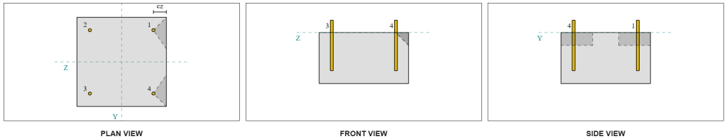
左右対称のデザインなので, Vz せん断に抵抗するアンカーも次のように識別されます。 シングルアンカー. 考えてみましょう アンカー 1 もう一度計算のために.
を計算するには 垂直荷重 on Anchor 1, we divide the Vz shear by the total number of anchors nearest to the edge only. を計算するには parallel load on Anchor 1, we divide the Vy shear by the total number of anchors.
\(
V_{\perp} = frac{V_{と}}{n_{a,s}}
= frac{5 \,\テキスト{kN}}{2}
= 2.5 \,\テキスト{kN}
\)
\(
V_{\平行} = frac{V_{そして}}{n_{anc}}
= frac{5 \,\テキスト{kN}}{4}
= 1.25 \,\テキスト{kN}
\)
\(
V_{エド} = sqrt{ \左( V_{\perp} \正しい)^ 2 + \左( V_{\平行} \正しい)^ 2 }
\)
\(
V_{エド} = sqrt{ \左( 2.5 \,\テキスト{kN} \正しい)^ 2 + \左( 1.25 \,\テキスト{kN} \正しい)^ 2 }
= 2.7951 \,\テキスト{kN}
\)
Using a similar approach to Check #2, 結果として生じる ブレイクアウト耐性 for the edge perpendicular to Vz shear is:
\(
V_{Rd,c} = frac{V_{Rk,c}}{\それを計算するために{マク}}
= frac{4.8435 \,\テキスト{kN}}{1.5}
= 3.229 \,\テキスト{kN}
\)
以来 2.7951 kN < 3.229 kN, the shear breakout capacity for Vz shear is 十分な.
小切手 #4: コンクリートのプリアウト容量を計算します
の計算 shear pryout resistance involves determining the nominal capacity of the anchors against tension breakout. The reference for tension breakout capacity is に 1992-4:2018, 句 7.2.1.4. A detailed discussion of tension breakout is already covered in the SkyCiv Design Example with Tension Load and will not be repeated in this design example.
From the SkyCiv software calculations, the nominal capacity of the section for tension breakout is 44.61 kN.
次に、使用します に 1992-4:2018, Equation 7.39a, to obtain the design characteristic resistance. 使用する k8 = 2, the capacity is 59.48 kN.
\(
V_{Rd,cp} = frac{k_8 N_{cbg}}{\gamma_c}
= frac{2 \回 44.608 \,\テキスト{kN}}{1.5}
= 59.478 \,\テキスト{kN}
\)
In the shear pryout check, すべてのアンカーが有効です 完全なせん断荷重に耐える場合. SkyCiv ソフトウェアによって生成された画像から, すべての失敗円錐投影が互いに重なり合う, アンカーを アンカーグループ.
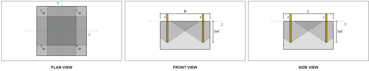
したがって, アンカー グループに必要な抵抗は、アンカー グループの合成せん断荷重の合計です。 7.07 kN.
\(
V_{レス} = sqrt{(v_y)^ 2 + (V_Z)^ 2}
= sqrt{(5 \,\テキスト{kN})^ 2 + (5 \,\テキスト{kN})^ 2}
= 7.0711 \,\テキスト{kN}
\)
\(
V_{エド} = left(\フラク{V_{レス}}{n_{anc}}\正しい) n_{a,G1}
= left(\フラク{7.0711 \,\テキスト{kN}}{4}\正しい) \回 4
= 7.0711 \,\テキスト{kN}
\)
以来 7.0711 kN < 59.478 kN, シアープラアウト能力は 十分な.
小切手 #5: アンカーロッドのせん断耐力を計算する
アンカーロッドのせん断耐力の計算は、せん断荷重がモーメントアームで適用されるかどうかによって異なります。. これを決定します, 参照します に 1992-4:2018, 句 6.2.2.3, グラウトの厚さと材質はどこですか, デザイン内の留め具の数, 留め具の間隔, などの要素がチェックされます.
の SkyCYVベースプレート設計ソフトウェア 必要なチェックをすべて実行して、 せん断荷重はレバーアームの有無にかかわらず作用します. この設計例の場合, せん断荷重は次のように決定されます。 ない レバーアームで適用. したがって, を使用しております に 1992-4:2018, 句 7.2.2.3.1, 容量方程式の場合.
We begin by calculating the characteristic resistance of the steel fastener using に 1992-4:2018, 方程式 7.34.
\(
V^0_{Rk,s} = k_6 A_s f_{あなた,anc}
= 0.5 \回 113.1 \,\テキスト{んん}^2 Times 800 \,\テキスト{MPa}
= 45.239 \,\テキスト{kN}
\)
次, we apply the factor for the 延性 of the single anchor or the anchor group, taking k7 = 1.
\(
V_{Rk,s} = k_7 V^{0}_{Rk,s}
= 1 \回 45.239 \,\テキスト{kN}
= 45.239 \,\テキスト{kN}
\)
We then obtain the partial factor for steel shear failure を使用して に 1992-4:2018, テーブル 4.1. For an anchor with 8.8 素材, the resulting partial factor is:
\(
\それを計算するために{MS,剪断}
= max left( 1.0 \左( \フラク{F_{あなた,anc}}{F_{そして,anc}} \正しい), \, 1.25 \正しい)
= max left( 1 \[object Window]{800 \,\テキスト{MPa}}{640 \,\テキスト{MPa}}, \, 1.25 \正しい)
= 1.25
\)
Applying this factor to the characteristic resistance, 設計抵抗は 36.19 kN.
\(
V_{Rd,s} = frac{V_{Rk,s}}{\それを計算するために{MS,剪断}}
= frac{45.239 \,\テキスト{kN}}{1.25}
= 36.191 \,\テキスト{kN}
\)
の required shear resistance per anchor rod is the resultant shear load divided by the total number of anchor rods, which calculates to 1.77 kN.
\(
V_{エド} = frac{\平方根{ (v_y)^ 2 + (V_Z)^ 2 }}{n_{anc}}
\)
\(
V_{エド} = frac{\平方根{ (5 \,\テキスト{kN})^ 2 + (5 \,\テキスト{kN})^ 2 }}{4}
= 1.7678 \,\テキスト{kN}
\)
以来 1.7678 kN < 36.191 kN, the anchor rod steel shear capacity is 十分な.
小切手 #6: ベースプレートの支持力を計算する
追加の base plate bearing resistance check was introduced in a later update of the software. お願いします refer to this link for a sample calculation and detailed explanation.
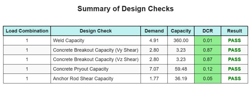
設計の概要
の SkyCYVベースプレート設計ソフトウェア このデザインの例の段階的な計算レポートを自動的に生成できます. また、実行されたチェックとその結果の比率の概要も提供します, 情報を一目で理解しやすくします. 以下はサンプルの概要表です, レポートに含まれています.
SkyCIVサンプルレポート
SkyCiv ベース プレート設計レポートから期待できる詳細レベルと明瞭さのレベルを確認してください。. The report includes all key design checks, 方程式, 結果は明確で読みやすい形式で表示されます. It is fully compliant with design standards. SkyCiv ベース プレート カリキュレーターを使用して生成されたサンプル レポートを表示するには、以下をクリックしてください。.
ベースプレートソフトウェアを購入します
他のSkyCIVモジュールなしで、ベースプレートデザインモジュールのフルバージョンを単独で購入する. これにより、ベースプレートデザインの完全な結果が得られます, 詳細なレポートとその他の機能を含む.