CSA S16を使用したベースプレートデザインの例:19 およびCSA A23.3:19
問題ステートメント
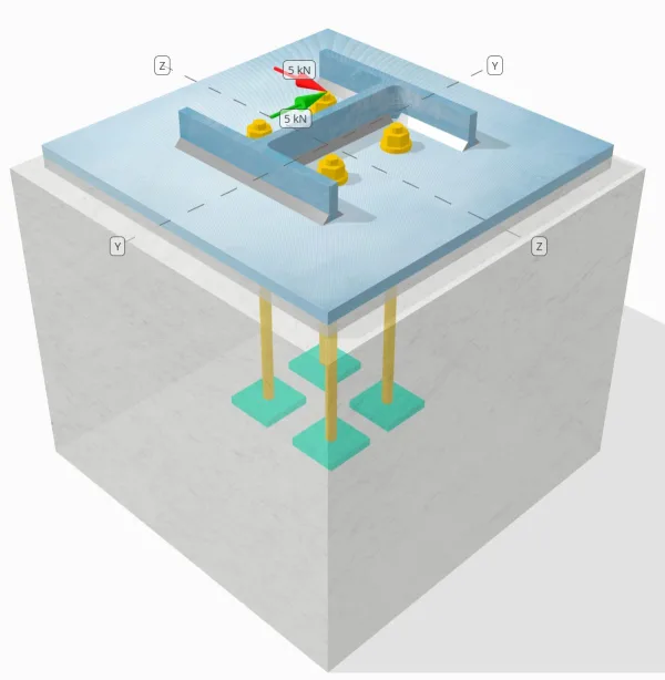
設計された柱とベース プレートの接続が十分な接続であるかどうかを判断します。 Vy=5-kN そして Vz=5-kN せん断荷重.
指定されたデータ
カラム:
列セクション: HP200x54
列エリア: 6840.0 んん2
列素材: 350W
ベースプレート:
ベースプレートの寸法: 400 mm x 400 んん
ベースプレートの厚さ: 13 んん
ベースプレート材料: 300W
グラウト:
グラウトの厚さ: 13 んん
コンクリート:
具体的な寸法: 450 mm x 450 んん
コンクリートの厚さ: 380 んん
コンクリート材料: 20.68 MPa
ひび割れまたは破損していません: 割れた
アンカー:
アンカーの直径: 12.7 んん
効果的な埋め込み長: 300 んん
プレートワッシャーの厚さ: 0 んん
プレートワッシャー接続: 番号
溶接:
溶接サイズ: 8 んん
フィラー金属分類: E43xx
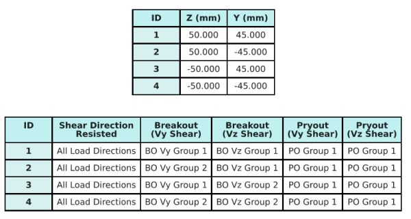
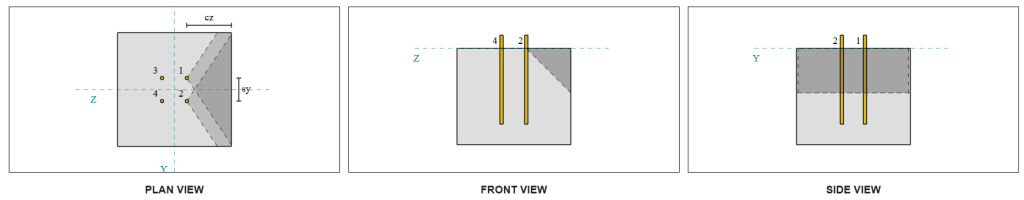
アンカーデータ (から SkyCIV計算機):
SkyCiv 無料ツールでモデルを作成する
無料のオンライン ツールを使用して、上記のベース プレート設計を今すぐモデル化してください。! サインアップは必要ありません.
定義
ロードパス:
デザインは以下を踏襲しています CSA A23.3:2019 の基準と推奨事項 AISC 設計ガイド 1, 3RDエディション. 柱にかかるせん断荷重は溶接部を介してベースプレートに伝達されます。, そして支持コンクリートまで アンカーロッド. この例では、摩擦ラグとせん断ラグは考慮されていません。, これらのメカニズムは現在のソフトウェアではサポートされていないため、.
デフォルトでは, の 加えられたせん断荷重はすべてのアンカーに分散されます, 溶接プレートワッシャーの使用またはその他の工学的手段による. 各アンカーが運ぶ荷重は、次の 3 つの要素を使用して決定されます。 (3) に記載されている事例 CSA A23.3:2019 条項 D.7.2.1 および図 D.13. 各アンカーは荷重を下の支持コンクリートに伝達します。. これらの参考文献に従った荷重分布は、荷重伝達の仮定の連続性を確保するためにアンカー鋼のせん断強度をチェックするときにも使用されます。.
代替として, ソフトウェアにより、簡素化されたより保守的な仮定が可能になります, どこ せん断荷重全体が、荷重がかかるエッジに最も近いアンカーにのみ割り当てられます。. この場合, せん断容量チェックは、これらのエッジアンカーだけで実行されます, 潜在的なせん断障害が控えめに対処されていることを確認します.
アンカーグループ:
の SkyCYVベースプレート設計ソフトウェア どのアンカーが評価するためのアンカーグループの一部であるかを識別する直感的な機能が含まれています コンクリートせん断ブレークアウト そして コンクリートせん断格子 障害.
アン アンカーグループ 投影された抵抗領域が重複する2つ以上のアンカーとして定義されます. この場合, アンカーは一緒に行動します, そして、それらの組み合わせ抵抗は、グループの適用された負荷に対してチェックされます.
あ シングルアンカー 投影抵抗領域が他のものと重複しないアンカーとして定義されます. この場合, アンカーは単独で作用します, そして、そのアンカーに加えられたせん断力は、個々の抵抗に対して直接チェックされます.
この区別により、せん断関連の故障モードを評価する際に、ソフトウェアがグループの動作と個々のアンカーパフォーマンスの両方をキャプチャできます。.
段階的な計算
小切手 #1: 溶接容量を計算します
最初のステップは、を計算することです 総溶接長 せん断に抵抗するために利用可能. 溶接全長, ルウェルド, すべての側面の溶接を合計することによって得られます.
\( L_{溶接} = 2b_f + 2(d_{col} – 2T_F – 2r_{col}) + 2(B_F – t_w – 2r_{col}) \)
\( L_{溶接} = 2 \207 倍,text{んん} + 2 \回 (204,\テキスト{んん} – 2 \11.3 倍,text{んん} – 2 \9.7 倍,text{んん}) + 2 \回 (207,\テキスト{んん} – 11.3,\テキスト{んん} – 2 \9.7 倍,text{んん}) = 1090.6,text{んん} \)
この溶接長を使用します, yの適用されたせん断力- Z方向は分割されて平均を決定します 単位長さあたりのせん断力 それぞれの方向に:
\( v_{年度} = frac{v_y}{L_{溶接}} = frac{5,\テキスト{kN}}{1090.6,\テキスト{んん}} = 0.0045846,text{kN / mm} \)
\( v_{fz} = frac{V_Z}{L_{溶接}} = frac{5,\テキスト{kN}}{1090.6,\テキスト{んん}} = 0.0045846,text{kN / mm} \)
の 結果として生じるせん断需要 次に、二乗和の平方根を使用して単位長さあたりの値が決定されます。 (SRSS) 方法.
\( v_f = sqrt{\左((v_{年度})^2右) + \左((v_{fz})^2右)} \)
\( v_f = sqrt{\左((0.0045846,\テキスト{kN / mm})^2右) + \左((0.0045846,\テキスト{kN / mm})^2右)} = 0.0064836,text{kN / mm} \)
次, 溶接容量は使用して計算されます CSA S16:19 句 13.13.2.2, ASを取得する方向強度係数を使用します kds=1.0 は控えめにします. フランジとウェブの両方における 8mm 溶接の溶接能力は次のとおりです。:
\( v_r = 0.67phi t_{w,フランジ}X_u = 0.67 \回 0.67 \5.657 倍,text{んん} \430 倍,text{MPa} = 1.092,text{kN / mm} \)
\( v_r = 0.67phi t_{w,ウェブ}X_u = 0.67 \回 0.67 \5.657 倍,text{んん} \430 倍,text{MPa} = 1.092,text{kN / mm} \)
統治者 すみ肉溶接能力 です:
\( v_{r,フィレ} = min(v_r, v_i) = min(1.092\,\テキスト{kN / mm}, 1.092\,\テキスト{kN / mm}) = 1.092,text{kN / mm} \)
この溶接接続の場合, 電極の強度 過一致しない 卑金属の強度. したがって, 卑金属チェックは管理されていないため、実行する必要はありません.
以来 0.0064 kN / mm < 1.092 kN / mm, 因数分解された溶接能力は 十分な.
小切手 #2: vyせん断によるコンクリートブレイクアウト容量を計算します
垂直エッジ容量:
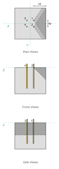
各アンカーの ca1 値を使用して破壊円錐を投影する, ソフトウェアは、これらのアンカーの破壊円錐が重なっていることを特定しました。. したがって, それらを次のものとして扱うことができます アンカーグループ. を参照してください CSA A23.3:19 図. D.13, なぜなら、<ca1, を使用しております 場合 3 せん断破壊に対するアンカーグループの抵抗を決定する. さらに, 支援が決まりました ない 狭いメンバーになる, したがって、ca1 距離は変更せずに直接使用されます。.
場合 3:
ケースで考慮される総力 3 それは 完全なせん断力 Vy方向に沿って. このせん断力はフロントアンカーのみに適用されます。.
\( V_{ファペルプ,ケース3} = V_y = 5,text{kN} \)
アンカー グループの容量を計算するには, を使用しております CSA A23.3:19 D.7.2項. の 最大投影面積 単一のアンカーの場合、次を使用して計算されます。 式 D.34 実際のCAと寸法.
\( A_{Vco} = 4.5(c_{a1、g1})^2 = 4.5 \回 (180\,\テキスト{んん})^2 = 145800,text{んん}^ 2 \)
アンカー グループの実際の投影面積を取得するには, 最初に決定します 破壊面の幅:
\( b_{VC} = min(c_{\テキスト{左},G1}, 1.5c_{a1、g1}) + (\分(S_{\テキスト{和},バツ,G1}, 3c_{a1、g1}(n_{バツ,G1} – 1))) + \分(c_{\テキスト{正しい},G1}, 1.5c_{a1、g1}) \)
\( b_{VC} = min(175\,\テキスト{んん}, 1.5 \180 倍,テキスト{んん}) + (\分(100\,\テキスト{んん}, 3 \180 倍,テキスト{んん} \回 (2-1))) + \分(175\,\テキスト{んん}, 1.5 \180 倍,テキスト{んん}) \)
\( b_{VC} = 450,テキスト{んん} \)
の 破壊面の高さ です:
\( それを計算するために{VC} = min(1.5c_{a1、g1}, t_{\テキスト{コンク}}) = min(1.5 \180 倍,テキスト{んん}, 380\,\テキスト{んん}) = 270,テキスト{んん} \)
これにより、 総面積 なので:
\( A_{VC} = b_{VC}.それを計算するために{VC} = 450,テキスト{んん} \270 倍,テキスト{んん} = 121500,テキスト{んん}^ 2 \)
次に、使用します CSA A23.3:19 式 D.35 および D.36 基本的なシングルアンカーブレークアウト強度を得るために.
\( V_{br1} = 0.58左(\フラク{\分(の, 8D_A)}{D_A}\正しい)^{0.2}\平方根{\フラク{D_A}{んん}}\ファイラムダ_asqrt{\フラク{f’_c}{MPa}}\左(\フラク{c_{a1、g1}}{んん}\正しい)^{1.5}R(N) \)
\( V_{br1} = 0.58 \倍左(\フラク{\分(300\,\テキスト{んん}, 8 \12.7 倍,text{んん})}{12.7\,\テキスト{んん}}\正しい)^{0.2} \回 sqrt{\フラク{12.7\,\テキスト{んん}}{1\,\テキスト{んん}}} \回 0.65 \回 1 \回 sqrt{\フラク{20.68\,\テキスト{MPa}}{1\,\テキスト{MPa}}} \倍左(\フラク{180\,\テキスト{んん}}{1\,\テキスト{んん}}\正しい)^{1.5} \回 1 \0.001 倍,text{kN} \)
\( V_{br1} = 22.364,text{kN} \)
\( V_{br2} = 3.75lambda_aphisqrt{\フラク{f’_c}{MPa}}\左(\フラク{c_{a1、g1}}{んん}\正しい)^{1.5}R(N) \)
\( V_{br2} = 3.75 \回 1 \回 0.65 \回 sqrt{\フラク{20.68\,\テキスト{MPa}}{1\,\テキスト{MPa}}} \倍左(\フラク{180\,\テキスト{んん}}{1\,\テキスト{んん}}\正しい)^{1.5} \回 1 \0.001 倍,text{kN} = 26.769,text{kN} \)
2 つの条件の間の支配力は次のとおりです。:
\( V_{br} = min(V_{\テキスト{br1}}, V_{\テキスト{br2}}) = min(22.364\,\テキスト{kN}, 26.769\,\テキスト{kN}) = 22.364,text{kN} \)
次, 偏心係数を計算します, エッジ効果係数, と厚さ係数を使用して CSA A23.3:19 D.7.2.5条項, D.7.2.6, およびD.7.2.8.
の 偏心因子 です:
\( \psi_{ec,V } = min 左(1.0, \フラク{1}{1 + \フラク{2および ’_N}{3c_{a1、g1}}}\正しい) = min 左(1, \フラク{1}{1 + \フラク{2\回0}{3\180 倍,テキスト{んん}}}\正しい) = 1 \)
の エッジ効果係数 です:
\( \psi_{ed,V } = min 左(1.0, 0.7 + 0.3\左(\フラク{c_{a2、g1}}{1.5c_{a1、g1}}\正しい)\正しい) = min 左(1, 0.7 + 0.3 \倍左(\フラク{175\,\テキスト{んん}}{1.5 \180 倍,テキスト{んん}}\正しい)\正しい) = 0.89444 \)
の 厚さ係数 です:
\( \psi_{h,V } = max 左(\平方根{\フラク{1.5c_{a1、g1}}{t_{\テキスト{コンク}}}}, 1.0\正しい) = max 左(\平方根{\フラク{1.5 \180 倍,テキスト{んん}}{380\,\テキスト{んん}}}, 1\正しい) = 1 \)
最後に, アンカーグループのブレイクアウトの強さ, を使用して計算 CSA A23.3:19 D.7.2.1項, です:
\( V_{cbgperp} = left(\フラク{A_{VC}}{A_{Vco}}\正しい)\psi_{ec,V }\psi_{ed,V }\psi_{c,V }\psi_{h,V }V_{br} \)
\( V_{cbgperp} = left(\フラク{121500\,\テキスト{んん}^ 2}{145800\,\テキスト{んん}^ 2}\正しい) \回 1 \回 0.89444 \回 1 \回 1 \22.364 倍,text{kN} = 16.669,text{kN} \)
Vy せん断の計算された容量は、 垂直方向 です 16.669 kN.
平行エッジ容量:
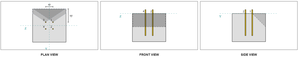
途中での失敗 負荷と平行なエッジ このシナリオでも可能です, したがって、平行エッジのコンクリートブレークアウト容量を決定する必要があります. 新しい失敗円錐投影により、関係するアンカーが異なります。. 以下の図に基づいています, の 失敗円錐の投影が重なり合う; したがって, アンカーは再び アンカーグループ.
場合 3:
使用するケースはまだ 場合 3 以来<ca1. したがって, このアンカー グループが受ける負荷は、 完全な Vy せん断荷重.
\( V_{ファペルプ,ケース3} = V_y = 5,text{kN} \)
それから私たちはフォローします 同じ手順 垂直容量については.
の故障面 個別のアンカー です:
\( A_{Vco} = 4.5(c_{a1、g1})^2 = 4.5 \回 (175\,\テキスト{んん})^2 = 137810,text{んん}^ 2 \)
の 実際の破損面 アンカーグループの:
\( b_{VC} = min(c_{\テキスト{底},G1}, 1.5c_{a1、g1}) + (\分(S_{\テキスト{和},そして,G1}, 3c_{a1、g1}(n_{そして,G1} – 1))) + \分(c_{\テキスト{上},G1}, 1.5c_{a1、g1}) \)
\( b_{VC} = min(180\,\テキスト{んん}, 1.5 \175 倍,テキスト{んん}) + (\分(90\,\テキスト{んん}, 3 \175 倍,テキスト{んん} \回 (2-1))) + \分(180\,\テキスト{んん}, 1.5 \175 倍,テキスト{んん}) \)
\( b_{VC} = 450,テキスト{んん} \)
\( それを計算するために{VC} = min(1.5c_{a1、g1}, t_{\テキスト{コンク}}) = min(1.5 \175 倍,テキスト{んん}, 380\,\テキスト{んん}) = 262.5,text{んん} \)
\( A_{VC} = b_{VC}それを計算するために{VC} = 450,テキスト{んん} \262.5 倍,text{んん} = 118130,テキスト{んん}^ 2 \)
同様に, の 基本的なシングルアンカーブレークアウト 強み 次のように計算されます:
\( V_{br1} = 0.58左(\フラク{\分(の, 8D_A)}{D_A}\正しい)^{0.2}\平方根{\フラク{D_A}{んん}}\ファイラムダ_asqrt{\フラク{f’_c}{MPa}}\左(\フラク{c_{a1、g1}}{んん}\正しい)^{1.5}R(N) \)
\( V_{br1} = 0.58 \倍左(\フラク{\分(300\,\テキスト{んん}, 8 \12.7 倍,text{んん})}{12.7\,\テキスト{んん}}\正しい)^{0.2} \回 sqrt{\フラク{12.7\,\テキスト{んん}}{1\,\テキスト{んん}}} \回 0.65 \回 1 \回 sqrt{\フラク{20.68\,\テキスト{MPa}}{1\,\テキスト{MPa}}} \倍左(\フラク{175\,\テキスト{んん}}{1\,\テキスト{んん}}\正しい)^{1.5} \回 1 \0.001 倍,text{kN} \)
\( V_{br1} = 21.438,text{kN} \)
\( V_{br2} = 3.75lambda_aphisqrt{\フラク{f’_c}{MPa}}\左(\フラク{c_{a1、g1}}{んん}\正しい)^{1.5}R(N) \)
\( V_{br2} = 3.75 \回 1 \回 0.65 \回 sqrt{\フラク{20.68\,\テキスト{MPa}}{1\,\テキスト{MPa}}} \倍左(\フラク{175\,\テキスト{んん}}{1\,\テキスト{んん}}\正しい)^{1.5} \回 1 \0.001 倍,text{kN} = 25.661,text{kN} \)
の 統治力 です:
\( V_{br} = min(V_{\テキスト{br1}}, V_{\テキスト{br2}}) = min(21.438\,\テキスト{kN}, 25.661\,\テキスト{kN}) = 21.438,text{kN} \)
次に、計算します 偏心因子 そして 厚さ係数:
\( \psi_{ec,V } = min 左(1.0, \フラク{1}{1 + \フラク{2および ’_N}{3c_{a1、g1}}}\正しい) = min 左(1, \フラク{1}{1 + \フラク{2\回0}{3\175 回,テキスト{んん}}}\正しい) = 1 \)
\( \psi_{h,V } = max 左(\平方根{\フラク{1.5c_{a1、g1}}{t_{\テキスト{コンク}}}}, 1.0\正しい) = max 左(\平方根{\フラク{1.5 \175 倍,テキスト{んん}}{380\,\テキスト{んん}}}, 1\正しい) = 1 \)
のために ブレイクアウトエッジ効果係数, 私たちはそれを次のように解釈します 1.0 CSA A23.3用:19 D.7.2.1c項. 加えて, 垂直エッジのブレークアウト容量の値は次のように取得されます。 式 D.33 を使用して計算された値の 2 倍 (アンカーグループの場合).
の 因数分解 アンカーグループのブレイクアウト能力 です:
\( V_{cbgr並列} = 2左(\フラク{A_{VC}}{A_{Vco}}\正しい)\psi_{ec,V }\psi_{ed,V }\psi_{c,V }\psi_{h,V }V_{br} \)
\( V_{cbgr並列} = 2 \倍左(\フラク{118130\,\テキスト{んん}^ 2}{137810\,\テキスト{んん}^ 2}\正しい) \回 1 \回 1 \回 1 \回 1 \21.438 倍,text{kN} = 36.752,text{kN} \)
- のために 垂直エッジ 失敗, 以来 5 kN < 16.7 kN, コンクリートせん断ブレークアウト容量はです 十分な.
- のために 平行エッジ 失敗, 以来 5 kN < 36.8 kN, コンクリートせん断ブレークアウト容量はです 十分な.
VZせん断によるコンクリートブレイクアウト容量を計算します
ベースプレートにもVzせん断を施します, それで失敗は終わります Vzせん断に対して垂直および平行 チェックする必要があります. 同じアプローチを使用します, 垂直容量と平行容量が計算されます 16.6 kN と 37.3 kN, それぞれ.
垂直エッジ:
平行エッジ:
これらの容量は、必要な強度と比較されます.
- のために 垂直エッジ 失敗, 以来 5 kN < 16.6 kN, 因数分解されたコンクリートせん断ブレークアウト能力は、 十分な.
- のために 平行エッジの故障, 以来 5 kN < 37.3 kN, 因数分解されたコンクリートせん断ブレークアウト能力は、 十分な.
小切手 #4: コンクリートのプリアウト容量を計算します
コンクリートコーン プラアウトの失敗 で使用されているのと同じコーンです。 引張破断チェック. せん断格子容量を計算します, の 公称引張破断強さ 単一のアンカーまたはアンカー グループの数を最初に決定する必要があります. 引張破断チェックの詳細な計算については、すでに説明されています。 緊張負荷のためのSkyCIVデザインの例 ここでは繰り返しません.
せん断ブレークアウトのアンカー グループの決定は、せん断プライアウトのアンカー グループの決定とは異なることに注意することが重要です。. デザイン内のアンカーをチェックして、アンカーが適切であるかどうかを判断する必要があります。 グループまたは単一のアンカーとして機能する. の分類は、 狭いセクションとしてサポート も検証する必要があり、緊張のブレイクアウトに使用されるのと同じ条件に従う必要があります。.
SkyCiv ソフトウェアによると, アンカーグループの公称引張破断強さは、 60.207 kN. プライアウト係数を使用すると、 2.0, の 因数分解されたプラアウト容量 です:
\( V_{CPGR} = k_{cp}N_{CBR} = 2 \60.207 倍,text{kN} = 120.41,text{kN} \)
必要な強度は、 結果として 適用されるせん断荷重の. すべてのアンカーは単一のグループに属しているため、, 結果として生じるせん断の合計がグループに割り当てられます。.
\( V_{FA} = sqrt{((v_y)^ 2) + ((V_Z)^ 2)} = sqrt{((5\,\テキスト{kN})^ 2) + ((5\,\テキスト{kN})^ 2)} = 7.0711,text{kN} \)
\( V_{FA} = left(\フラク{V_{FA}}{なし}\正しい)n_{a,G1} = left(\フラク{7.0711\,\テキスト{kN}}{4}\正しい) \回 4 = 7.0711,text{kN} \)
以来 7.07 kN < 120.4 kN, 因数分解されたプラアウト容量は 十分な.
小切手 #5: アンカーロッドのせん断耐力を計算する
この設計例でのことを思い出してください。, せん断はすべてのアンカーに分散されます. の アンカーあたりの総せん断荷重 したがって、Vy 負荷の分担と Vz 負荷の分担の結果です。. また、 統治事件 せん断ブレークアウトチェックに使用されます.
Vyシャー用, 場合 3 統治している.
\( V_{FA,そして} = frac{v_y}{n_{と,G1}} = frac{5\,\テキスト{kN}}{2} = 2.5,テキスト{kN} \)
同様に, Vzシャー用, 場合 3 統治している.
\( V_{FA,と} = frac{V_Z}{n_{そして,G1}} = frac{5\,\テキスト{kN}}{2} = 2.5,テキスト{kN} \)
これにより、 アンカーロッドにかかるせん断力 なので:
\( V_{FA} = sqrt{((V_{FA,そして})^ 2) + ((V_{FA,と})^ 2)} = sqrt{((2.5\,\テキスト{kN})^ 2) + ((2.5\,\テキスト{kN})^ 2)} = 3.5355,text{kN} \)
この設計例では, グラウトが存在する. したがって, アンカーロッドも経験します 偏心せん断による曲げ. これを説明するには, を適用することもできます CSA A23.3 に基づくグラウト削減係数:19 D.7.1.3項 または CSA S16 を使用してせん断と曲げの相互作用を確認する:19 句 13.12.1.4.
この計算のために, 私たちは、を使用することを選択しました 0.8 削減 CSA A23.3 の係数. 個別の技術的判断を可能にするため, の SkyCIVベースプレートソフトウェア この減少係数を無効にし、代わりにせん断曲げ相互作用チェックを使用するオプションを提供します。. この機能は、 ベースプレートフリーツール.
CSA A23.3 アンカーロッドせん断耐力:
最初, CSA A23.3 を使用してアンカーロッドのせん断耐力を計算します。. の 最小引張応力 アンカーロッドの:
\( f_{uta} = min(F_{u _anc}, 1.9F_{最初}, 860) = min(400\,\テキスト{MPa}, 1.9 \248.2 倍,text{MPa}, 860.00\,\テキスト{MPa}) = 400,テキスト{MPa} \)
の 因数分解アンカーロッドせん断耐力, を使用して計算 CSA A23.3:19 式 D.31 および条項 D.7.1.3, です:
\( V_{サール,a23} = 0.8A_{知っている,V }\phi_s0.6f_{uta}R = 0.8 \92 倍,テキスト{んん}^2 Times 0.85 \回 0.6 \400 倍,テキスト{MPa} \回 0.75 = 11.258,text{kN} \)
注意してください 0.8 グラウトが存在するため、ここでは低減係数が適用されます。. このせん断耐力の低下により、アンカー ロッドの曲がりがさらに大きくなります。.
CSA S16 アンカーロッドせん断耐力:
CSA S16 容量の場合, だけ せん断能力はチェックですd, 偏心せん断による曲げは CSA A23.3 チェックですでに考慮されているため.
の 因数分解せん断耐力 を使用して計算されます CSA S16:19 句 25.3.3.3.
\( V_{r,s16} = 0.7phi_m 0.6n A_{sr} F_{u _anc} = 0.7 \回 0.67 \回 0.6 \回 1 \126.68 倍,text{んん}^2 times 400,text{MPa} = 14.255,text{kN} \)
両方の方法が考慮されていることを確認するには, 統治能力は 2 つの値のうち小さい方と見なされます。, それは 11.258 kN.
以来 3.54 kN < 11.258 kN, 因数分解されたアンカーロッドのせん断耐力は、 十分な.
設計の概要
の SkyCYVベースプレート設計ソフトウェア このデザインの例の段階的な計算レポートを自動的に生成できます. また、実行されたチェックとその結果の比率の概要も提供します, 情報を一目で理解しやすくします. 以下はサンプルの概要表です, レポートに含まれています.
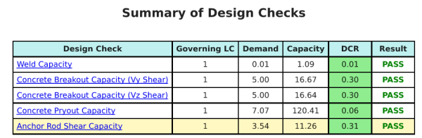
SkyCIVサンプルレポート
SkyCiv ベース プレート設計レポートから期待できる詳細レベルと明瞭さのレベルを確認してください。. The report includes all key design checks, 方程式, 結果は明確で読みやすい形式で表示されます. It is fully compliant with design standards. SkyCiv ベース プレート カリキュレーターを使用して生成されたサンプル レポートを表示するには、以下をクリックしてください。.
ベースプレートソフトウェアを購入します
他のSkyCIVモジュールなしで、ベースプレートデザインモジュールのフルバージョンを単独で購入する. これにより、ベースプレートデザインの完全な結果が得られます, 詳細なレポートとその他の機能を含む.