AISCを使用したベースプレートのデザイン例 360-22 およびACI 318-19
問題ステートメント
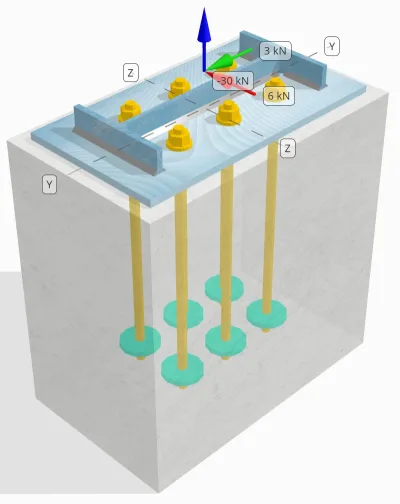
設計された柱とベースプレートの接続が十分であるかどうかを判断します。 30 kN引張荷重, 3 kN Vyせん断荷重, そして 6 kN Vz せん断荷重.
指定されたデータ
カラム:
列セクション: 幅14×30
列エリア: 5709.7 んん2
列素材: A992
ベースプレート:
ベースプレートの寸法: 250 mm x 250 んん
ベースプレートの厚さ: 12 んん
ベースプレート材料: A992
グラウト:
グラウトの厚さ: 0 んん
コンクリート:
具体的な寸法: 300 mm x 500 んん
コンクリートの厚さ: 500 んん
コンクリート材料: 20.7 MPa
ひび割れまたは破損していません: 割れた
アンカー:
アンカーの直径: 16 んん
効果的な埋め込み長: 400 んん
アンカーエンディング: 円形プレート
埋め込まれたプレートの直径: 70 んん
埋め込まれたプレートの厚さ: 10 んん
鋼材: F1554 Gr.55
せん断面のねじ山: 付属
溶接:
溶接サイズ: 7 んん
フィラー金属分類: E70XX
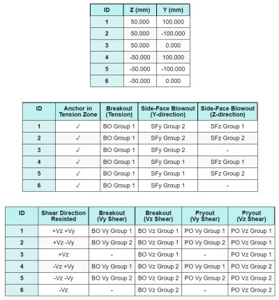
アンカーデータ (から SkyCIV計算機):
SkyCiv 無料ツールでモデルを作成する
無料のオンライン ツールを使用して、上記のベース プレート設計を今すぐモデル化してください。! サインアップは必要ありません.
注意
この設計例の目的は、同時せん断荷重とアキシアル荷重を含む容量チェックのための段階的な計算を実証することです。. 必要なチェックの一部については、前の設計例ですでに説明しました。. 各セクションに記載されているリンクを参照してください.
段階的な計算
小切手 #1: 溶接容量を計算します
同時荷重下での溶接能力を決定するには, まず、次の理由による溶接需要を計算する必要があります。 せん断荷重 そしてそれによる溶接需要 引張荷重. これを参照してください リンク せん断に対する溶接要求を取得する手順用, そしてこれ リンク 引張溶接の要求に対応.
このデザインの場合, の ウェブでの溶接需要 引張荷重による次のことがわかります。, ここで、ストレスは次のように表されます 単位長さあたりの力.
\(r_{あなた,\テキスト{ウェブ}} = frac{T_{あなた,\テキスト{アンカー}}}{l_{\テキスト{eff}}} = frac{5\ \テキスト{kN}}{93.142\ \テキスト{んん}} = 0.053681\ \テキスト{kN / mm}\)
さらに, の 柱断面の任意の部分の溶接応力 せん断荷重によるものは次のように決定されます。:
\(v_{あなた} = frac{v_y}{L_{\テキスト{溶接}}} = frac{3\ \テキスト{kN}}{1250.7\ \テキスト{んん}} = 0.0023987\ \テキスト{kN / mm}\)
\(v_{に} = frac{V_Z}{L_{\テキスト{溶接}}} = frac{6\ \テキスト{kN}}{1250.7\ \テキスト{んん}} = 0.0047973\ \テキスト{kN / mm}\)
引張荷重とせん断荷重の組み合わせがかかるため、 ウェブ, 結果を取得する必要があります. これを単位長さあたりの力で表すと, 我々は持っています:
\(r_u = sqrt{(r_{あなた,\テキスト{ウェブ}})^ 2 + (v_{あなた})^ 2 + (v_{に})^ 2}\)
\(r_u = sqrt{(0.053681\ \テキスト{kN / mm})^ 2 + (0.0023987\ \テキスト{kN / mm})^ 2 + (0.0047973\ \テキスト{kN / mm})^ 2}\)
\(r_u = 0.053949\ \テキスト{kN / mm}\)
のために フランジ, せん断応力のみが存在します. したがって, 結果は:
\(r_u = sqrt{(v_{あなた})^ 2 + (v_{に})^ 2}\)
\(r_u = sqrt{(0.0023987\ \テキスト{kN / mm})^ 2 + (0.0047973\ \テキスト{kN / mm})^ 2} = 0.0053636\ \テキスト{kN / mm}\)
次, を計算します 溶接能力. フランジ用, 私たちは角度を決めます θ を使用して Vz そして あなた 負荷.
\( \theta = \tan^{-1}\!\左(\フラク{v_{あなた}}{v_{に}}\正しい) = \tan^{-1}\!\左(\フラク{0.0023987\ \テキスト{kN / mm}}{0.0047973\ \テキスト{kN / mm}}\正しい) = 0.46365\ \テキスト{作業} \)
したがって, の KDS 係数と溶接能力は次を使用して計算されます。 AISC 360-22 Eq. J2-5 そして Eq. J2-4.
\(k_{DS} = 1.0 + 0.5(\それなし(\シータ))^{1.5} = 1 + 0.5 \回 (\それなし(0.46365\ \テキスト{作業}))^{1.5} = 1.1495\)
\(\Phi R_{ん,フラグ} = ファイ,0.6,F_{exx}\,E_w\,k_{DS} = 0.75 \回 0.6 \回 480\ \テキスト{MPa} \回 4.95\ \テキスト{んん} \回 1.1495 = 1.2291\ \テキスト{kN / mm}\)
ウェブ用, 角度を計算します θ 別の式を使用する. =建物またはその他の構造物の場所での地面からの高さ おお 溶接軸に平行な荷重を表すため、式で使用されます。.
\( \theta = \cos^{-1}\!\左(\フラク{v_{あなた}}{r_u}\正しい) = \cos^{-1}\!\左(\フラク{0.0023987\ \テキスト{kN / mm}}{0.053949\ \テキスト{kN / mm}}\正しい) = 1.5263\ \テキスト{作業} \)
使用する AISC 360-22 Eq. J2-5 そして Eq. J2-4, の KDS 係数とその結果として得られる溶接能力は同じ方法で決定されます。.
\(k_{DS} = 1.0 + 0.5(\それなし(\シータ))^{1.5} = 1 + 0.5 \回 (\それなし(1.5263\ \テキスト{作業}))^{1.5} = 1.4993\)
\(\Phi R_{ん,ウェブ} = ファイ,0.6,F_{exx}\,E_w\,k_{DS} = 0.75 \回 0.6 \回 480\ \テキスト{MPa} \回 4.95\ \テキスト{んん} \回 1.4993 = 1.603\ \テキスト{kN / mm}\)
最後に, 私たちは実行します 卑金属チェック コラムとベースプレートの両方に, 次に、支配的な卑金属容量を取得します。.
\( \Phi R_{NBM,col} = ファイ,0.6,F_{あなた,col}\,t_{col,半分} = 0.75 \回 0.6 \回 448.2\ \テキスト{MPa} \回 3.429\ \テキスト{んん} = 0.6916\ \テキスト{kN / mm} \)
\( \Phi R_{NBM,血圧} = ファイ,0.6,F_{あなた,血圧}\,t_{血圧} = 0.75 \回 0.6 \回 400\ \テキスト{MPa} \回 12\ \テキスト{んん} = 2.1595\ \テキスト{kN / mm} \)
\( \Phi R_{NBM} = minbig(\Phi R_{NBM,血圧},\ \Phi R_{NBM,col}\大きい) = min(2.1595\ \テキスト{kN / mm},\ 0.6916\ \テキスト{kN / mm}) = 0.6916\ \テキスト{kN / mm} \)
次に、以下を比較します。 すみ肉溶接能力 そして 卑金属の容量 での溶接需要に対応 フランジとウェブを別々に.
以来 0.053949 kN / mm < 0.6916 kN / mm, 溶接容量はです 十分な.
小切手 #2: 張力負荷によるベースプレートの曲げ容量を計算する
ベース プレートの曲げ降伏能力の設計例は、「張力に関するベース プレートの設計例」ですでに説明されています。. 段階的な計算については、このリンクを参照してください。.
小切手 #3: アンカーロッド引張容量を計算します
アンカー ロッドの引張耐力の設計例は、「張力に関するベース プレートの設計例」ですでに説明されています。. 段階的な計算については、このリンクを参照してください。. 段階的な計算については、このリンクを参照してください。.
小切手 #4: コンクリートのブレイクアウト容量を緊張して計算します
張力ブレークアウトにおけるコンクリートの容量の設計例は、張力用のベース プレートの設計例ですでに説明されています。. 段階的な計算については、このリンクを参照してください。. 段階的な計算については、このリンクを参照してください。.
小切手 #5: アンカープルアウト容量を計算します
アンカーの引き抜き能力の設計例は、「張力のベース プレート設計例」ですでに説明されています。. 段階的な計算については、このリンクを参照してください。. 段階的な計算については、このリンクを参照してください。.
小切手 #6: 埋め込みプレートの曲げ能力を計算します
埋め込みプレートの曲げ降伏能力の補足チェックのための設計例は、張力に関するベース プレートの設計例ですでに説明されています。. 段階的な計算については、このリンクを参照してください。.
小切手 #7: y方向のサイドフェイスブローアウト容量を計算します
を計算するには 横顔吹き出し (SFBO) 容量, まず合計を決定します 張力 エッジに最も近いアンカー上. このチェックのために, に沿ってエッジの容量を評価します。 Y方向.
Y 方向に沿った SFBO の破壊円錐投影が重なるため、, アンカーは アンカーグループ.
アンカーグループの総張力需要は次のように計算されます。:
\(N_{する} = left(\フラク{N_X}{n_{a,t}}\正しい) n_{そして,G1} = left(\フラク{30\ \テキスト{kN}}{6}\正しい) \回 3 = 15\ \テキスト{kN}\)
次, を決定します エッジ距離:
\(c_{と,\分} = min(c_{\テキスト{左},G1},\ c_{\テキスト{正しい},G1}) = min(100\ \テキスト{んん},\ 200\ \テキスト{んん}) = 100\ \テキスト{んん}\)
\(c_{そして,\分} = min(c_{\テキスト{上},G1},\ c_{\テキスト{底},G1}) = min(150\ \テキスト{んん},\ 150\ \テキスト{んん}) = 150\ \テキスト{んん}\)
これらのエッジ距離を使用する, を計算します アンカーグループの容量 に従い、 ACI 318-19 Eq. (17.6.4.1).
\(N_{として} = left(\フラク{1 + \dfrac{c_{そして,\分}}{c_{と,\分}}}{4} + \フラク{S_{和,そして,G1}}{6\,c_{と,\分}}\正しい)\回 13 \倍左(\フラク{c_{と,\分}}{1\ \テキスト{んん}}\正しい)\回 sqrt{\フラク{A_{brg}}{\テキスト{んん}^ 2}}\ \lambda_a sqrt{\フラク{f_c}{\テキスト{MPa}}}\回 0.001\ \テキスト{kN}\)
\(N_{として} = left(\フラク{1 + \dfrac{150\ \テキスト{んん}}{100\ \テキスト{んん}}}{4} + \フラク{200\ \テキスト{んん}}{6\回 100\ \テキスト{んん}}\正しい)\回 13 \倍左(\フラク{100\ \テキスト{んん}}{1\ \テキスト{んん}}\正しい)\回 sqrt{\フラク{3647.4\ \テキスト{んん}^ 2}{1\ \テキスト{んん}^ 2}}\回 1 \回 sqrt{\フラク{20.68\ \テキスト{MPa}}{1\ \テキスト{MPa}}}\回 0.001\ \テキスト{kN}\)
\(N_{として} = 342.16\ \テキスト{kN}\)
元の方程式では, アンカー間隔が以下の場合、縮小係数が適用されます。 6約₁, 頭付きアンカーに十分なエッジ距離があると仮定した場合. しかしながら, この設計例では, 以来 ca₂ < 3約₁, SkyCiv 計算ツールは、エッジ容量の減少を考慮して追加の削減係数を適用します。.
最後に, の 設計SFBO容量 です:
\(\ファイN_{として} = \phi\,N_{として} = 0.7 \回 342.16\ \テキスト{kN} = 239.51\ \テキスト{kN}\)
以来 15 kN < 239.51 kN, Y 方向に沿った SFBO 容量は次のとおりです。 十分な.
小切手 #8: Z方向のサイドフェイスブローアウト容量を計算します
と同じアプローチに従います 小切手 #7, アンカーグループに最も近いアンカーに対する総張力需要 Z方向 エッジは:
\(N_{する} = left(\フラク{N_X}{n_{a,t}}\正しい)n_{と,G1} = left(\フラク{30\ \テキスト{kN}}{6}\正しい)\回 2 = 10\ \テキスト{kN}\)
の エッジ距離 次のように計算されます:
\(c_{そして,\分} = min(c_{\テキスト{上},G1},\ c_{\テキスト{底},G1}) = min(150\ \テキスト{んん},\ 350\ \テキスト{んん}) = 150\ \テキスト{んん}\)
\(c_{と,\分} = min(c_{\テキスト{左},G1},\ c_{\テキスト{正しい},G1}) = min(100\ \テキスト{んん},\ 100\ \テキスト{んん}) = 100\ \テキスト{んん}\)
の 公称SFBO容量 次に次のように決定されます:
\(N_{として} = left(\フラク{1 + \dfrac{c_{と,\分}}{c_{そして,\分}}}{4} + \フラク{S_{和,と,G1}}{6\,c_{そして,\分}}\正しい)\回 13 \倍左(\フラク{c_{そして,\分}}{1\ \テキスト{んん}}\正しい)\回 sqrt{\フラク{A_{brg}}{\テキスト{んん}^ 2}}\ \lambda_a sqrt{\フラク{f_c}{\テキスト{MPa}}}\回 0.001\ \テキスト{kN}\)
\(N_{として} = left(\フラク{1 + \dfrac{100\ \テキスト{んん}}{150\ \テキスト{んん}}}{4} + \フラク{100\ \テキスト{んん}}{6\回 150\ \テキスト{んん}}\正しい)\回 13 \倍左(\フラク{150\ \テキスト{んん}}{1\ \テキスト{んん}}\正しい)\回 sqrt{\フラク{3647.4\ \テキスト{んん}^ 2}{1\ \テキスト{んん}^ 2}}\回 1 \回 sqrt{\フラク{20.68\ \テキスト{MPa}}{1\ \テキスト{MPa}}}\回 0.001\ \テキスト{kN}\)
\(N_{として} = 282.65\ \テキスト{kN}\)
エッジ距離があるので ca₂ まだ未満です 3約₁, 同じ修正された削減係数が適用されます.
最後に, の 設計SFBO容量 です:
\(\ファイN_{として} = \phi\,N_{として} = 0.7 \回 282.65\ \テキスト{kN} = 197.86\ \テキスト{kN}\)
以来 10 kN < 197.86 kN, に沿ったSFBO容量 Z方向 です 十分な.
小切手 #9: ブレークアウト容量の計算 (vy shear)
Vy せん断におけるコンクリートのブレイクアウト能力の設計例は、せん断用のベース プレートの設計例ですでに説明されています。. 段階的な計算については、このリンクを参照してください。.
小切手 #10: ブレークアウト容量の計算 (VZせん断)
Vy せん断におけるコンクリートのブレイクアウト能力の設計例は、せん断用のベース プレートの設計例ですでに説明されています。. 段階的な計算については、このリンクを参照してください。.
小切手 #11: プラアウト能力の計算 (vy shear)
Vy せん断によるプラアウト破壊に対するコンクリートの能力の設計例は、「せん断に対するベース プレートの設計例」ですでに説明されています。. 段階的な計算については、このリンクを参照してください。.
小切手 #12: プラアウト能力の計算 (VZせん断)
Vy せん断によるプラアウト破壊に対するコンクリートの能力の設計例は、「せん断に対するベース プレートの設計例」ですでに説明されています。. 段階的な計算については、このリンクを参照してください。.
小切手 #13: アンカーロッドのせん断耐力を計算する
アンカーロッドのせん断耐力の設計例は、「せん断用のベースプレート設計例」ですでに説明されています。. 段階的な計算については、このリンクを参照してください。.
小切手 #14: アンカーロッドのせん断力と軸方向耐力を計算する (AISC)
せん断荷重と軸方向荷重を組み合わせた場合のアンカー ロッドの耐力を決定するには, を使用しております AISC 360-22 Eq. J3-3a. この計算機では, 式は、代わりに修正されたせん断強度として結果を表すように再配置されます。.
の せん断需要 として定義されます アンカーあたりのせん断荷重.
\(V_{する} = V_{する} = 2.5\ \テキスト{kN}\)
の 緊張要求 として表されます 引張応力 アンカーロッドの中に.
\(f_{うーん} = frac{N_{する}}{A_{ロッド}} = frac{5\ \テキスト{kN}}{201.06\ \テキスト{んん}^ 2} = 24.868\ \テキスト{MPa}\)
の 修正されたせん断耐力 アンカーロッドの強度は次のように計算されます。:
\(f’_{NV} = \min\!\左(1.3\,F_{NV} – \左(\フラク{F_{NV}}{\phi f_{nt}}\正しい) f_{うーん},\; F_{NV}\正しい)\)
\(f’_{NV} = \min\!\左(1.3\回 232.69\ \テキスト{MPa} – \左(\フラク{232.69\ \テキスト{MPa}}{0.75\回 387.82\ \テキスト{MPa}}\正しい)\回 24.868\ \テキスト{MPa},\; 232.69\ \テキスト{MPa}\正しい) = 232.69\ \テキスト{MPa}\)
次に、この強さを次のように乗算します。 アンカーエリア を使用して AISC 360-22 Eq. J3-2.
\(\ファイR_{ん,\テキスト{AISC}} = phi f’_{NV} A_{\テキスト{ロッド}} = 0.75 \回 232.69\ \テキスト{MPa} \回 201.06\ \テキスト{んん}^2 = 35.09\ \テキスト{kN}\)
以来 2.5 kN < 35.09 kN, アンカーロッドの容量は 十分な.
小切手 #15: 相互作用チェックを計算する (ACI)
せん断荷重と引張荷重を組み合わせた状態でアンカー ロッドの耐力を確認する場合は、 ACI, 別のアプローチが適用される. 完全を期すために, 私たちも実行します ACI 相互作用チェック この計算では, 他のものを含む 具体的な相互作用のチェック 同様に.
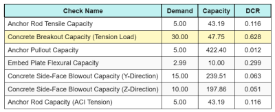
結果は次のとおりです すべての ACI 張力チェックの比率:
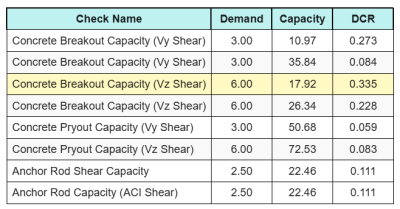
そして、その結果がこれです すべての ACI せん断チェックの比率:
最大の比率を持つチェックを取得し、次を使用してそれを最大インタラクション比率と比較します。 ACI 318-19 Eq. 17.8.3.
\(私_{整数} = frac{N_{する}}{\ファイ N_n} + \フラク{V_{する}}{\ファイV_n} = frac{30}{47.749} + \フラク{6}{17.921} = 0.96308\)
以来 0.96 < 1.2, インタラクションチェックは 十分な.
設計の概要
の SkyCYVベースプレート設計ソフトウェア このデザインの例の段階的な計算レポートを自動的に生成できます. また、実行されたチェックとその結果の比率の概要も提供します, 情報を一目で理解しやすくします. 以下はサンプルの概要表です, レポートに含まれています.
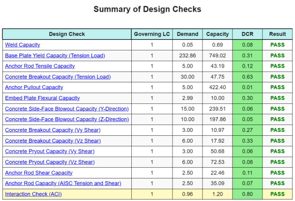
SkyCIVサンプルレポート
SkyCiv ベース プレート設計レポートから期待できる詳細レベルと明瞭さのレベルを確認してください。. The report includes all key design checks, 方程式, 結果は明確で読みやすい形式で表示されます. It is fully compliant with design standards. SkyCiv ベース プレート カリキュレーターを使用して生成されたサンプル レポートを表示するには、以下をクリックしてください。.
ベースプレートソフトウェアを購入します
他のSkyCIVモジュールなしで、ベースプレートデザインモジュールのフルバージョンを単独で購入する. これにより、ベースプレートデザインの完全な結果が得られます, 詳細なレポートとその他の機能を含む.