
A column splice joins one column to the one above it. Columns arrive in mill lengths, and a building taller than that length needs its columns spliced, usually a few feet above floor level where the erector can reach the joint from the deck. Splices also turn up in retrofit work, where a column is extended, replaced or reinforced after a change in loading.
The splice has to carry whatever the column carries across the joint: axial compression, axial tension where uplift or overturning governs, Schub-, und Moment. AISC 360-16 sets out the procedures for each. This page walks through designing one in SkyCiv Connection Design.
Die Berechnungen hinter Säulenspleißverbindungen
A column splice is a slow connection to calculate by hand. Each plate has to be checked in tension, compression and bearing, each bolt group in shear, and the whole joint for block shear, all of it doubled because the upper and lower columns are separate connections either side of the splice. AISC 360-16 gives the procedure for the axial, shear and moment capacity of each of those pieces.
Mit der column splice calculator runs the same procedure. You supply the column sections, Plattengrößen, bolt specifications and loads, and it returns every check with its utilization ratio and the clause it came from, so the arithmetic stops being the part of the job that takes the time.
Schrauben oder Schweißen: Auswahl der richtigen Verbindungsmethode
Bolting is the usual choice for a column splice. A bolted splice is made in the air by an erector with a wrench, it tolerates the small misalignments that come with erecting a frame, and it can be slackened and adjusted if something does not line up. Welding a splice at height means preheat, position welding and inspection on a joint that is hard to reach.
Vorbereiten der Stützenkontaktfläche: Mit der “Fit zum Tragen” Ansatz
Where the column ends are prepared so the two sections sit in full contact, compression transfers through bearing rather than through the bolts. That usually means fewer bolts and thinner plates, because the plates only have to carry tension, Scherung und Moment.
It is a decision that has to reach the fabricator. Fit to bear is a preparation requirement on the shop drawings, not something the connection design can assume on its own, so if you design on that basis, say so on the drawing.
Die Notwendigkeit von Säulenspleißverbindungen
Splices appear wherever a column cannot be a single piece: buildings taller than the available mill length, sections that would be impossible to ship or lift in one, and retrofits where a column is extended or strengthened. In each case the splice has to reproduce the continuity the column would have had without it.
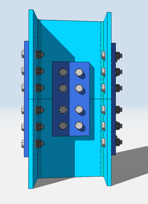
Designing a Column Splice in SkyCiv
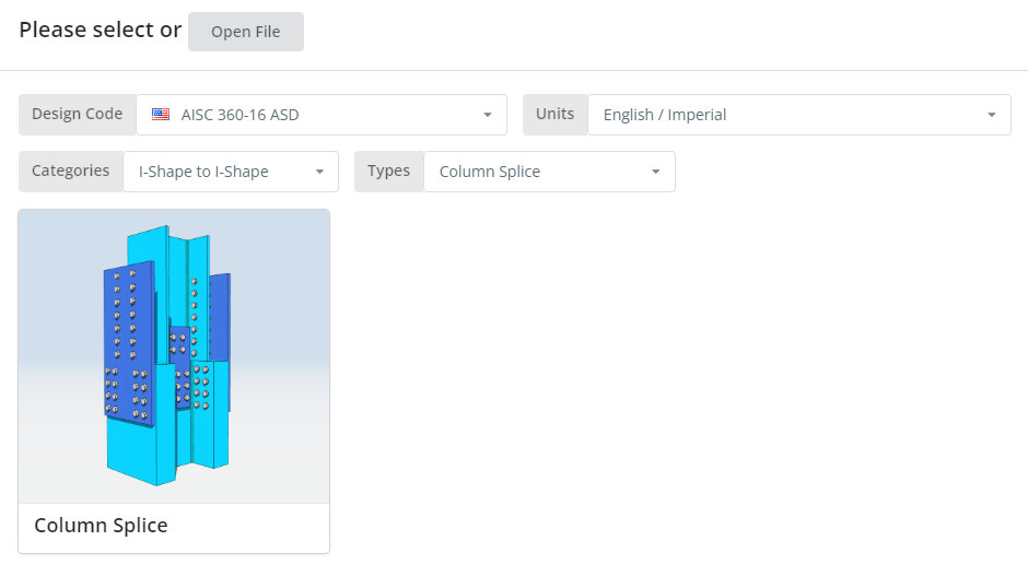
Der Designcode kann AISC sein 360-16 ASD oder LRFD, und Einheiten Englisch/Imperial oder SI/Metrisch. Drücke den “Säulenspleiß” Fliese.
Registerkarte Details
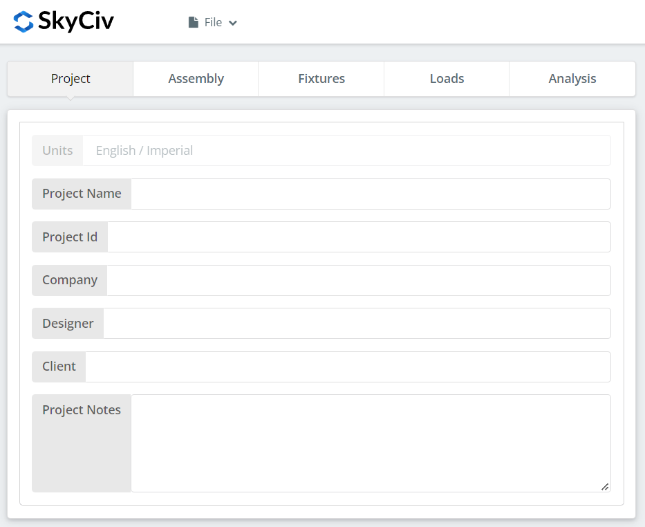
Tragen Sie hier die Projektdetails ein. Nichts davon ändert die Berechnungen, aber es geht in den Bericht über, which is what makes a set of designs traceable later.
Registerkarte „Montage“.
Unter „Assembly“ befinden sich drei Registerkarten: the Lower Column, the Upper Column, und die Verbindung, which holds the flange plate and web plate.
Registerkarte „Untere Spalte“.
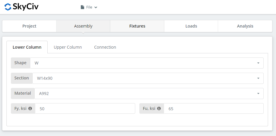
Specify the section and material grade of the lower column. A992 und A36 sind in der Liste; Für alles andere wählen Sie „Benutzerdefiniert“ und geben „Fy“ und „Fu“ ein.
Obere Spaltenregisterkarte
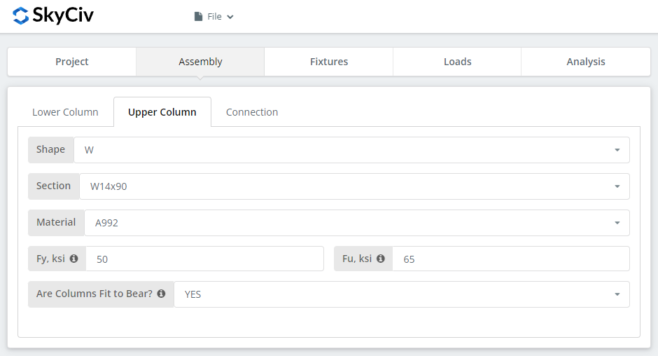
The same inputs, plus the option to declare the columns fit to bear. Wählen “JA” and the compressive load is designed at the column contact surface instead of through the bolted connection, which gives a more economical connection. Wie oben, that is a requirement you have to pass to the fabricator: the columns must actually be prepared to bear.
Registerkarte „Verbindung“.: Flanschplatte
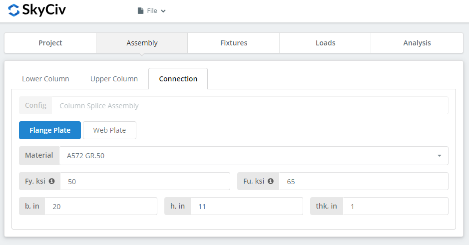
Set the flange plate properties: grade A36, A992 or A572 Gr.50, oder individuell mit Ihrem eigenen Fy und Fu, then b (Breite), h (Höhe) und denke (Dicke). Watch the 3D renderer as you type and check the plate geometry makes sense, in particular that there is room for the bolt group you are about to define on the Fixtures tab.
Registerkarte „Verbindung“.: Stegplatte
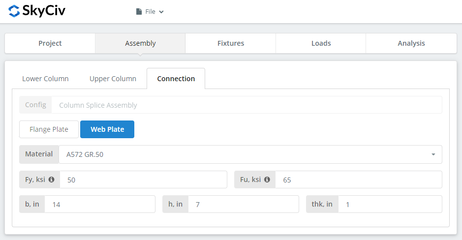
Same inputs as the flange plate. Check the renderer again before moving on.
Befestigung 1-4 Tab
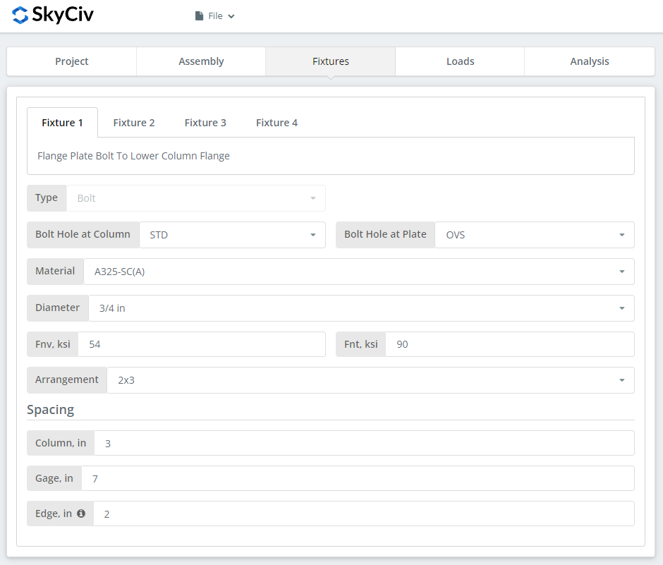
This is where the bolts are defined, one fixture per interface:
Befestigung 1 – Flanschplatte zum unteren Säulenflansch
Befestigung 2 – Flanschplatte zum oberen Säulenflansch
Befestigung 3 – Stegplatte zum unteren Stützensteg
Befestigung 4 – Stegplatte zum oberen Stützensteg
Zuerst, the bolt-hole types at the column flange or web and at the plates. Hersteller verlangen in der Regel Standardlöcher (STD) in the member and oversized holes (OVS) im Teller, was Passtoleranz vor Ort erkauft.
Als nächstes, das Schraubenmaterial oder die Schraubensorte: A307, A325, A490 oder Benutzerdefiniert. A325 und A490 sind Güten gemäß ASTM F3125, wodurch die älteren eigenständigen Spezifikationen konsolidiert wurden, so a drawing calling for A325 is calling for F3125 Grade A325. Wählen Sie N oder X für eine lagerartige Verbindung und SC für eine schlupfkritische Verbindung.
Gleitkritische Gelenke haben eine geringere konstruktive Schraubenkapazität als Lagergelenke, Verwenden Sie sie also dort, wo es tatsächlich auf Rutschfestigkeit ankommt: übergroße oder Langlöcher, Lastumkehr, oder Müdigkeit. In diesem Beispiel, using OVS holes in either the column or the plate means the bolts are automatically checked as slip-critical. Zwischen N und X, X gibt die größere Bolzenscherkapazität an, aber die Gewinde müssen aus der Scherebene ausgeschlossen werden, which the erector has to know about. Zwischen SC(Ein) und SC(B.), SC(B.) bietet eine größere Kapazität und erfordert eine gründlicher vorbereitete Verbindungsfläche, zum Beispiel SSPC-SP6 gewerbliche Strahlreinigung.
Dann der Bolzendurchmesser, ab 5.8″ bis 1-1/2″ oder die metrischen Äquivalente, und die Anordnung, bis zu 8 Bolzenreihen und 12 Bolzensäulen. Set the bolt row spacing, column spacing and gage. Mit der “Kante” input is the distance from the column end to the first bolt column.
For more on the fastener side of this, siehe Dokumentation unter Schrauben.
Registerkarte Lasten
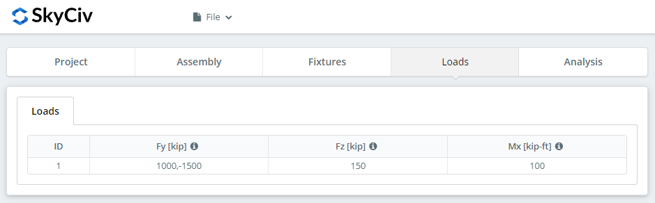
Enter the compressive or tensile load as ‘Fy’, the horizontal shear as ‘Fz’, and the strong axis moment as ‘Mx’. Hover the tooltips for the sign convention and direction of each.
Match the loads to the design method you picked at the start. LRFD berücksichtigt faktorisierte Lasten anhand der Bemessungsfestigkeit; ASD nimmt Betriebslasten entgegen der zulässigen Stärke auf. Die Software kann nicht erkennen, was Sie eingegeben haben, so mixing them produces a utilization ratio that means nothing.
Registerkarte Ergebnisse
Klicken “Führen Sie Designprüfungen durch”. Alles, was in den früheren Registerkarten fehlt, wird hier markiert und nicht stillschweigend standardmäßig übernommen.
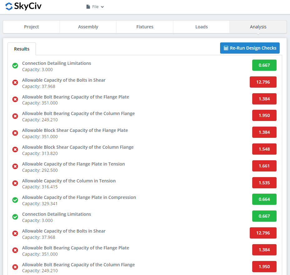
Die Zusammenfassung zeigt, ob die Verbindung erfolgreich war, with a utilization ratio against each check and the governing one called out. Wenn es fehlgeschlagen ist, Ändern Sie die Eingaben auf den vorherigen Registerkarten und klicken Sie auf “Designprüfungen erneut ausführen”. Wenn es vorbei ist, “Berechnungsbericht anzeigen” öffnet den Detailbericht.
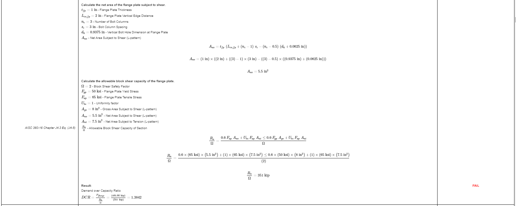
Das ist ein Auszug aus dem Bericht. Jede Prüfung enthält einen Verweis auf das AISC-Handbuch oder die AISC-Spezifikation, and the working is laid out the way the specification lays it out, so a reviewing engineer can follow it line by line instead of reverse-engineering a result.
Hierist eine PDF-Kopie des vollständigen detaillierten Berechnungsberichts.
Designing a beam splice instead? Mit der beam splice calculator works the same way.
Probieren Sie es selbst aus
The link below opens the module with the column splice already loaded. Enter your sections, Platten, bolts and loads, and every check and code reference is shown in full. Es läuft im Browser, ohne dass es etwas zu installieren gibt.
