In diesem Artikel werden zwei Beispiele für die Gestaltung von Stahlbetonplatten erläutert, einschließlich Biegen in eine Richtung und in beide Richtungen. Das Hauptziel besteht darin, die zwischen Handberechnungen und dem SkyCiv Plate Design Module erzielten Ergebnisse zu vergleichen. Wir werden Eurocode verwenden 2 für Stahlbetonkonstruktionen.
Bauvorschriften haben ähnliche Ansätze bei der Definition der typischen Fälle für Platten. Wenn Sie etwas mehr zu diesem Thema erfahren möchten, Wir empfehlen Ihnen, die folgenden Artikel zum Thema Plattendesign zu lesen ACI Slab Design Beispiel und Vergleich mit SkyCiv und Australian Standards AS3600 Slab Design Beispiel und Vergleich mit SkyCiv
Beispiel für ein Einwegplattendesign
Der erste zu analysierende Fall ist ein kleines einstöckiges Gebäude (Abbildung 1, Abbildung 2) das ein Plattenverhalten aufweist, das als in eine Richtung beschrieben wird.
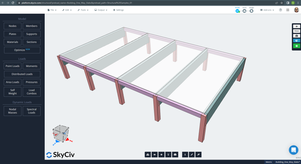
Abbildung 1. Einwegplatten in einem kleinen Gebäudebeispiel. (Strukturelles 3D, SkyCiv Cloud Engineering).
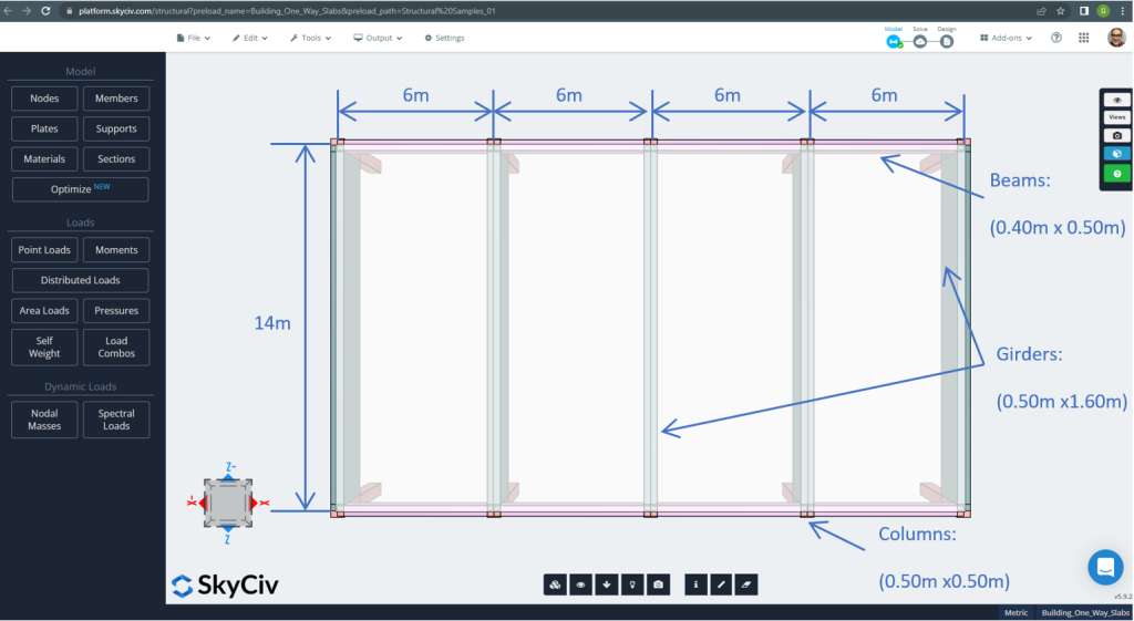
Abbildung 2. Einwegplatten in einem kleinen Gebäudebeispiel (Planabmessungen). (Strukturelles 3D, SkyCiv Cloud Engineering).
Für das Plattenbeispiel, Zusammenfassend, das Material, Elementeigenschaften, und jede Menge zu bedenken :
- Klassifizierung des Plattentyps: Eins – Art und Weise Verhalten \(\frac{L_2}{L_1} > 2 ; \frac{14 Mio.}{6 Mio.}=2,33 > 2.00 \) OK!
- Gebäudebesetzung: Wohnnutzung
- Plattendicke \(t_{Platte}=0.25m\)
- Dichte des Stahlbetons \(\rho_w = 25 \frac{kN}{m^3}\)
- Charakteristische Betondruckfestigkeit bei 28 Tage (C25\30) \(fck = 25 MPa \)
- Eigengewicht der Platte \(Dead = \rho_w \times t_{Platte} = 25 \frac{kN}{m^3} \mal 0,25m = 6.25 \frac {kN}{m^2}\)
- Überlagerte Eigenlast \(SD = 3.0 \frac {kN}{m^2}\)
- Live-Last \(L = 2.0 \frac {kN}{m^2}\)
Handberechnungen nach EN-2
In diesem Abschnitt, Wir berechnen die erforderliche Bewehrungsstahlbewehrung anhand der Referenz des Eurocode-Standards. Wir ermitteln zunächst das gesamte faktorisierte Biegemoment, das auf den einheitlichen Breitenstreifen der Platte ausgeübt werden muss.
- Eigengewicht, \(g = (3.0 + 6.25) \frac{kN}{m^2} \mal 1 m = 9.25 \frac{kN}{ Mio.}\)
- Live-Last, \(q = (2.0) \frac{kN}{m^2} \mal 1 m = 2.0 \frac{kN}{ Mio.}\)
- Grenzlast, \(Fd = 1.35\times g + 1.5\mal q = (1.35\mal 9.25 + 1.5\mal 2.0)\frac{kN}{ Mio.} =15.5 \frac{kN}{ Mio.} \)
Vor Erhalt der Stahlverstärkungsfläche, Wir müssen die Spannweiten-wirksamen Tiefenverhältnisse überprüfen. Zwei Hauptfälle:
| Struktursystem | Grundlegendes Verhältnis von Spannweite zu effektiver Tiefe | ||
|---|---|---|---|
| Faktor für Struktursystem K | Beton stark beansprucht %(\(\rho = 1.5 )\) | Beton leicht beansprucht %(\(\rho = 0.5 )\) | |
| 1. Endspannweite eines durchgehenden Trägers oder einer einseitig durchgehenden Platte oder einer zweiseitig durchgehenden Platte, die über eine lange Seite durchgehend ist | 1.3 | 18 | 26 |
| 2. Innenspannweite eines durchgehenden Trägers oder einer einseitig oder zweiseitig überspannenden Platte | 1.5 | 20 | 30 |
Der kritischste Fall betrifft Nummer eins, Also, Wir wählen ein Verhältnis von 26.
- \(t_{Min.}= frac{L.}{ICH WEISS}+cover+0.5\dot bar_{Durchmesser}= frac{6 Mio.}{26}+0.025m+0.5\times 12mm=0.26m \) ~ \(0.25m ). Die Gesamtdicke ist immer noch ausreichend, OK!
Jetzt, Es ist an der Zeit, den Tisch für einseitig durchgehende Platten zu verwenden:
| Supportbedingung beenden | Zunächst innere Unterstützung | In der Mitte der Innenspannweiten | An Innenstützen | ||||
|---|---|---|---|---|---|---|---|
| Gepinnt | Kontinuierlich | ||||||
| Äußere Unterstützung | Nahe der Mitte der Endspanne | Support beenden | Endspanne | ||||
| Moment | 0 | 0.086FL | – | 0.075FL | – | 0.063FL | – |
| 0.04FL | 0.086FL | 0.063FL | |||||
| Scheren | 0.4F. | – | – | – | |||
| 0.46F. | 0.6F. | 0.5F. | |||||
Wo:
- L ist die effektive Spanne
- F ist die Gesamttraglast im Feld (1.35Gk + 1.5Qk; Gk ist die Eigenlast und Qk die Nutzlast, beziehungsweise)
Es wird nur ein Fall erläutert (durchgehende Endunterstützung) und der Rest wird in der folgenden Tabelle angezeigt.
- \(F=Fd\times L = 15.5 \frac{kN}{ Mio.} \mal 6m = 93.0 kN \)
- \(M=0.04FL=0.04 \times 93.0 kN \times 6m= -22.32{kN}{ Mio.}\)
- \(d = 230 mm \)
- \(K=\frac{M.}{{b}{d^2}{f_{ck}}}= frac{22.32\mal 10^6 {N.}{mm}}{{1000mm}\mal{(230 mm)^ 2}\mal {25 \frac{N.}{mm^2}}}=0.016877\)
- \(l_a = 0.95 \)
- \(z=l_a \times d = 0.95\times 230mm = 218.50 mm)
- \(A_s = frac{M.}{{0.87}{f_{Ja}}{mit}}= frac{22.32\mal 10^6 {N.}{mm}}{0.87\mal 500 {N.}{mm^2} \mal {218.50mm} = 234.83 mm^2 }\)
- \(EIN_{s,Min.}=0,0013{b}{d}=0.0013\times 1000mm \times 230 mm =299 mm^2\)
- \(EIN_{st}=max(Als, EIN_{s,Min.}) = max(234.83, 299) mm^2 = 299 mm^2 \)
| Momente | Äußere negative Linke | Äußerlich positiv | Äußeres negatives Recht | Innere negative Linke | Innen positiv | Inneres negatives Recht |
|---|---|---|---|---|---|---|
| M-Wert, kN-m | 22.32 | 35.15 | 41.85 | 48.00 | 35.15 | 35.15 |
| K. | 0.0168 | 0.0266 | 0.03164 | 0.0362 | 0.0266 | 0.0266 |
| mit, mm | 218.50 | 218.50 | 218.50 | 218.50 | 218.50 | 218.50 |
| \(Als, mm^2\) | 234.83 | 369.815 | 440.31 | 505.011 | 369.815 | 369.815 |
| \(EIN_{s,Min.},mm^2\) | 299.00 | 299.00 | 299.00 | 299.00 | 299.00 | 299.00 |
| \(EIN_{st} {mm^2}\) | 299.00 | 369.815 | 440.31 | 505.011 | 369.815 | 369.815 |
Der nächste Schritt besteht darin, den Bewehrungsstahl mit dem Plate Design Module in SkyCiv zu berechnen. Bitte, Lesen Sie den folgenden Abschnitt weiter!.
Wenn Sie neu bei SkyCiv sind, Melden Sie sich an und testen Sie die Software selbst!
Ergebnisse des SkyCiv S3D Plate Design-Moduls
In diesem Abschnitt geht es um die Ermittlung der Stahlbewehrungsfläche, allerdings ausschließlich mithilfe der Software, bleibt die Plattendesign-Modul. Auf prägnante Weise, Wir zeigen die Ergebnisse oder wichtige Informationen nur durch Bilder.
Vor der Analyse des Modells, Wir müssen eine Plattenmaschenweite definieren. Einige Referenzen (2) Empfehlen Sie eine Größe für das Schalenelement von 1/6 der kurzen Spanne bzw 1/8 der langen Spanne, der kürzere von ihnen. Diesem Wert folgen, wir haben \(\frac{L2}{6}= frac{6 Mio.}{6} = 1 m \) oder \(\frac{L1}{8}= frac{14 Mio.}{8}=1,75m \); Als maximale empfohlene Größe gehen wir von 1 m und von der angewandten Maschenweite von 0,50 m aus.
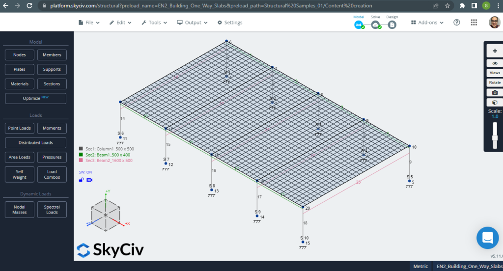
Abbildung 3. Platte vermascht. (Strukturelles 3D, SkyCiv Cloud Engineering).
Einmal haben wir unser analytisches Strukturmodell verbessert, Wir führen eine lineare elastische Analyse durch. Beim Entwerfen von Platten, Wir müssen prüfen, ob die vertikale Verschiebung kleiner als das vom Code zulässige Maximum ist. Eurocode 2 Es wurde eine maximale vertikale Verschiebung der Bedienbarkeit von festgelegt \(\frac{L.}{250}= frac{6000mm}{250}=24.0 mm\).
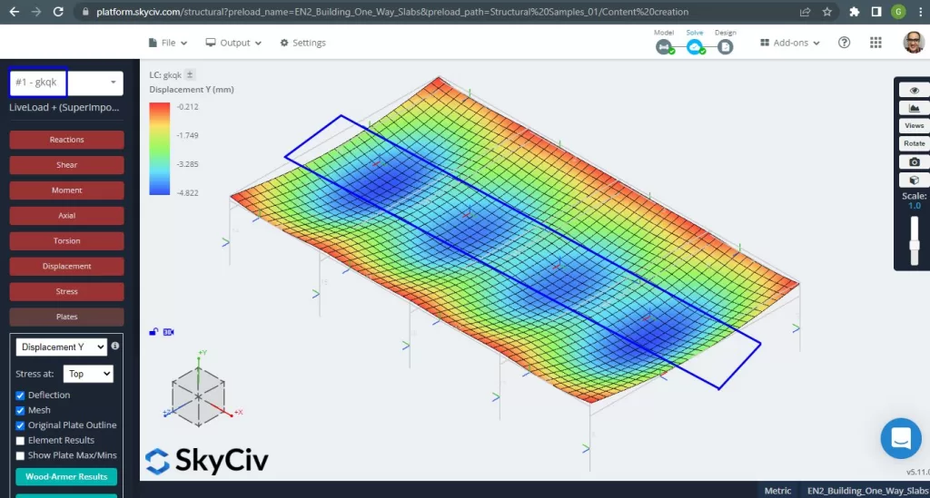
Abbildung 4. Vertikale Verschiebung, Maximalwerte in der Mitte der Spannweiten. (Strukturelles 3D, SkyCiv Cloud Engineering).
Vergleich der maximalen vertikalen Verschiebung mit dem codereferenzierten Wert, Die Steifigkeit der Platte ist ausreichend. \(4.822 mm < 24.00mm).
Die maximalen Momente in den Spannweiten der Platte liegen positiv in der Mitte und negativ an den Außen- und Innenstützen. Sehen wir uns diese Momentwerte in den folgenden Bildern an.
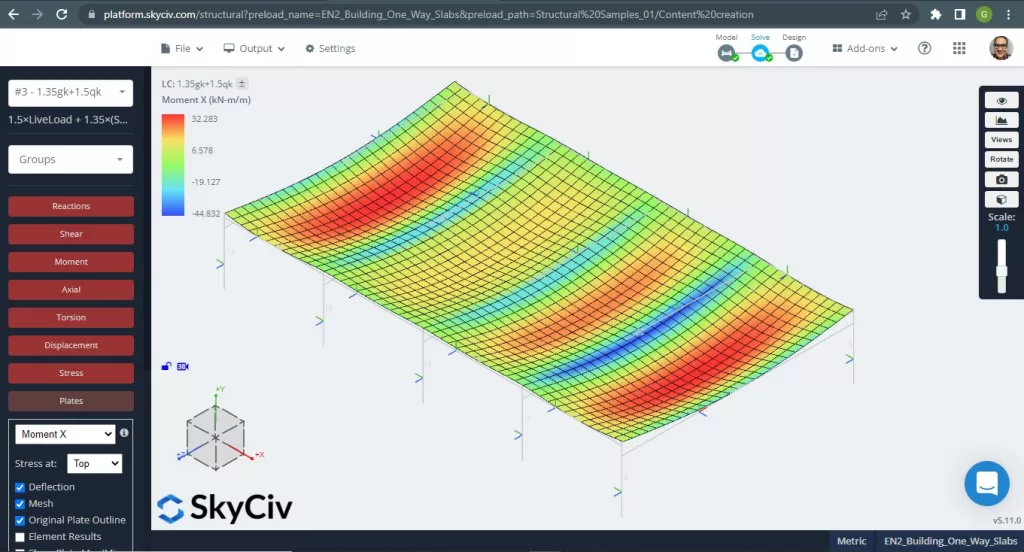
Abbildung 5. Biegemomente in X-Richtung. (Strukturelles 3D, SkyCiv Cloud Engineering).

Abbildung 6. Biegemomente in Y-Richtung. (Strukturelles 3D, SkyCiv Cloud Engineering).
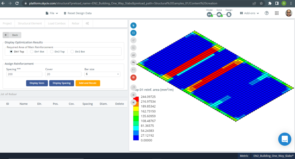
Abbildung 7. Stahlverstärkung für Richtung X oben. (Strukturelles 3D, SkyCiv Cloud Engineering).
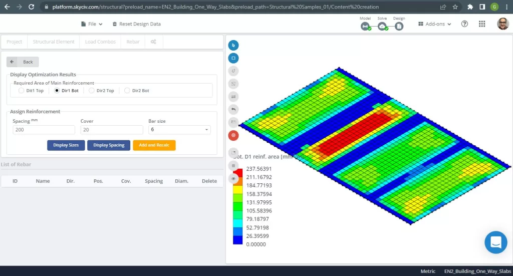
Abbildung 8. Stahlverstärkung für Richtung X unten. (Strukturelles 3D, SkyCiv Cloud Engineering).

Abbildung 9. Stahlbewehrung für Richtung Y oben. (Strukturelles 3D, SkyCiv Cloud Engineering).
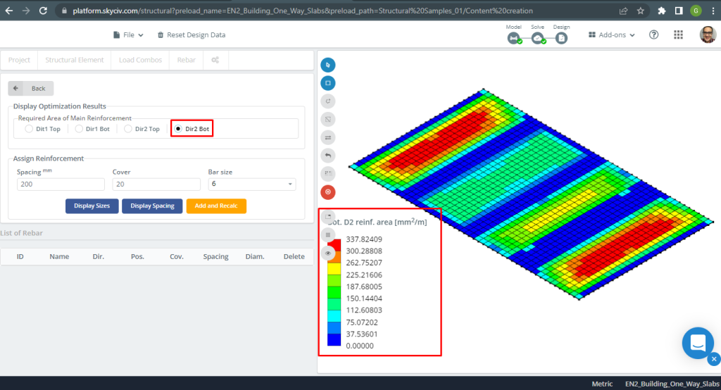
Abbildung 10. Stahlbewehrung für Richtung Y unten. (Strukturelles 3D, SkyCiv Cloud Engineering).
Ergebnisvergleich
Der letzte Schritt in diesem Beispiel für eine einseitige Deckenkonstruktion ist der Vergleich der durch die S3D-Analyse erhaltenen Stahlbewehrungsfläche (lokale Achsen “2”) und Handberechnungen.
| Momente und Stahlbereich | Äußere negative Linke | Äußerlich positiv | Äußeres negatives Recht | Innere negative Linke | Innen positiv | Inneres negatives Recht |
|---|---|---|---|---|---|---|
| \(EIN_{st, HandCalcs} {mm^2}\) | 299.00 | 369.82 | 440.31 | 505.011 | 369.82 | 369.82 |
| \(EIN_{st, S3D} {mm^2}\) | 308.41 | 337.82 | 462.61 | 462.61 | 262.75 | 308.41 |
| \(\Delta_{diff}\) (%) | 3.051 | 8.653 | 4.820 | 8.400 | 28.95 | 16.610 |
Wir können sehen, dass die Ergebnisse der Werte sehr nahe beieinander liegen. Dies bedeutet, dass die Berechnungen korrekt sind!
Wenn Sie neu bei SkyCiv sind, Melden Sie sich an und testen Sie die Software selbst!
Beispiel für ein zweiseitiges Plattendesign
Das SkyCiv 3D Plate Design Module ist eine leistungsstarke Software, die jede Art von Gebäude, die Sie sich vorstellen können, analysieren und entwerfen kann. Für das zweite Designplattenbeispiel, Wir haben uns für ein Flachdeckensystem entschieden (Zahl 11).
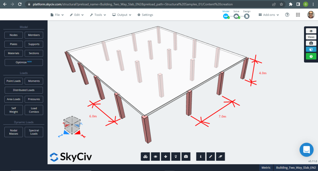
Abbildung 11. Einwegplatten in einem kleinen Gebäudebeispiel. (Strukturelles 3D, SkyCiv Cloud Engineering).
Für das Plattenbeispiel, Zusammenfassend, das Material, Elementeigenschaften, und jede Menge zu bedenken :
- Klassifizierung des Plattentyps: Zwei – Art und Weise Verhalten \(\frac{L_2}{L_1} \das 2 ; \frac{7 Mio.}{6 Mio.}=1.17 \le 2.00 \) OK!
- Gebäudebesetzung: Wohnnutzung
- Plattendicke \(t_{Platte}=0.30m\)
- Dichte des Stahlbetons \(\rho_w = 25 \frac{kN}{m^3}\)
- Charakteristische Betondruckfestigkeit bei 28 Tage (C25\30) \(fck = 25 MPa \)
- Eigengewicht der Platte \(Dead = \rho_w \times t_{Platte} = 25 \frac{kN}{m^3} \mal 0,30m = 7.5 \frac {kN}{m^2}\)
- Überlagerte Eigenlast \(SD = 3.0 \frac {kN}{m^2}\)
- Live-Last \(L = 2.0 \frac {kN}{m^2}\)
Handberechnungen nach EN-2
Der erste Schritt besteht darin, die Gesamttraglast zu definieren:
- Eigengewicht, \(g = (3.0 + 7.5) \frac{kN}{m^2} \mal 7 m = 73.50 \frac{kN}{ Mio.}\)
- Live-Last, \(q = (2.0) \frac{kN}{m^2} \mal 7 m = 14.00 \frac{kN}{ Mio.}\)
- Grenzlast, \(Fd = 1.35\times g + 1.5\mal q = (1.35\mal 73.50 + 1.5\mal 14.00)\frac{kN}{ Mio.} =120.225 \frac{kN}{ Mio.} \)
Zur Handberechnung, Die Struktur muss in eine Reihe gleichwertiger Rahmen unterteilt werden. Wir können die folgenden Methoden verwenden, um dieses Ziel zu erreichen:
- Momentenverteilung (Hardy-Cross-Methode) zur Rahmenanalyse.
- Steifigkeitsmethode zur Rahmenanalyse am Computer. Probier unser Steifigkeitsmatrix-Rechner.
- Eine vereinfachte Methode unter Verwendung der Momentenkoeffizienten für die Einwegrichtung, angepasst an die folgenden Anforderungen (Wir haben diese Methode aufgrund der Einfachheit des analysierten Modells ausgewählt):
- Die seitliche Stabilität ist nicht von den Decken-Stützen-Verbindungen abhängig (Wir analysieren das Gebäude nicht auf seitliche Belastungen);
- In der betrachteten Richtung sind mindestens drei Paneelreihen mit annähernd gleicher Spannweite vorhanden (Wir verfügen über vier bzw. drei Paneelreihen in beiden Hauptrichtungen);
- Die Buchtgröße überschreitet \(30m^2\) (Unser Modellbereich ist \(42m^2\)
Die für das Plattenbeispiel gewählte Dicke ist größer als der in der folgenden Tabelle angegebene maximale Mindestwert für den Feuerwiderstand.
| Standard-Feuerwiderstand | Mindestmaße (mm) | |
|---|---|---|
| Plattendicke, hs | Achsabstand, ein | |
| REI 60 | 180 | 15 |
| REI 90 | 200 | 25 |
| REI 120 | 200 | 35 |
| REI 240 | 200 | 50 |
In diesem Abschnitt, Wir werden nur die Berechnungen für die Längsrichtung und den Stützenstreifen entwickeln (Sie können gerne auch eine andere Richtung berechnen, die Quer, und für Mittelstreifen). Bevor wir tief in die Zahlen eintauchen, Zuerst müssen wir es in Streifen teilen: Mitte und Spalte. (Weitere Informationen zu Designstreifen, Schauen Sie sich diesen SkyCiv-Artikel an: Platten mit ACI-318 gestalten).
- Breite des Säulenstreifens: \(6m/4 = 1.50m\)
- Mittlere Streifenbreite: \(7 Mio. – 2\times 1.50m = 4.0m\)
EC2 ermöglicht die Zuweisung von Momenten in jedem Designstreifen gemäß der folgenden Tabelle
| Säulenstreifen | Mittelstreifen | |
|---|---|---|
| Negatives Moment an der Randstütze | 100% aber nicht mehr als \(0.17{Sei}{d^2}{f_{ck}}\) | 0 |
| Negatives Moment an der Innensäule | 60-80% | 40-20% |
| Positives Moment in der Spanne | 50-70% | 50-30% |
Wir haben die Prozentsätze der Momente für den zu analysierenden Stützenstreifen ausgewählt:
- Negatives Moment an der Randstütze: 100%.
- Negatives Moment an der Innensäule: 80%
- Positives Moment in der Spanne: 70%
Berechnung der Gesamtmomente der Designstreifen:
| Supportbedingung beenden | Zunächst innere Unterstützung | In der Mitte der Innenspannweiten | An Innenstützen | ||||
|---|---|---|---|---|---|---|---|
| Gepinnt | Kontinuierlich | ||||||
| Äußere Unterstützung | Nahe der Mitte der Endspanne | Support beenden | Endspanne | ||||
| Moment | 0 | 0.086FL | – | 0.075FL | – | 0.063FL | – |
| 0.04FL | 0.086FL | 0.063FL | |||||
| Scheren | 0.4F. | – | – | – | |||
| 0.46F. | 0.6F. | 0.5F. | |||||
Wo:
- L ist die effektive Spanne
- F ist die Gesamttraglast im Feld (1.35Gk + 1.5Qk; Gk ist die Eigenlast und Qk die Nutzlast, beziehungsweise)
Es wird nur ein Fall erläutert (Kontinuierliche Endunterstützung) und der Rest wird in der folgenden Tabelle angezeigt.
- \(F=Fd\times L = 120.225 \frac{kN}{ Mio.} \mal 6m = 721.35 kN \)
- \(M=0.04FL=0.04 \times 721.35 kN \times 6m= -173.124 {kN}{ Mio.}\)
- \(d = 280 mm \)
- \(K=\frac{M.}{{b}{d^2}{f_{ck}}}= frac{173.124\mal 10^6 {N.}{mm}}{{1500mm}\mal{(280 mm)^ 2}\mal {25 \frac{N.}{mm^2}}}=0.012637\)
- \(l_a = 0.95 \)
- \(z=l_a \times d = 0.95\times 280mm = 266.0 mm)
- \(A_s = frac{M.}{{0.87}{f_{Ja}}{mit}}= frac{173.124\mal 10^6 {N.}{mm}}{0.87\mal 500 {N.}{mm^2} \mal {266.0mm} = 214.0523 mm^2 }\)
- \(EIN_{s,Min.}=0,0013{b}{d}=0.0013\times 1500mm \times 280 mm =546 mm^2)
- \(EIN_{st}=max(Als, EIN_{s,Min.}) = max(234.83, 546) mm^2 = 299 mm^2 \)
| Momente | Äußere negative Linke | Äußerlich positiv | Äußeres negatives Recht | Innere negative Linke | Innen positiv | Inneres negatives Recht |
|---|---|---|---|---|---|---|
| M-Wert, kN-m | 173.124 | 191.125 | 260.064 | 298.281 | 191.125 | 218.429 |
| K. | 0.05897 | 0.06500 | 0.0884 | 0.101 | 0.06500 | 0.0743 |
| mit, mm | 266.00 | 266.00 | 266.00 | 266.00 | 266.00 | 266.00 |
| \(Als, mm^2\) | 1498.366 | 1651.761 | 2247.55 | 2577.835 | 1651.761 | 1887.727 |
| \(EIN_{s,Min.},mm^2\) | 546.00 | 546.00 | 546.00 | 546.00 | 546.00 | 546.00 |
| \(EIN_{st} {mm^2}\) | 1498.366 | 1651.761 | 2247.55 | 2577.835 | 1651.761 | 1887.727 |
Der nächste Schritt besteht darin, den Bewehrungsstahl mit dem Plate Design Module in SkyCiv zu berechnen. Bitte, Lesen Sie den folgenden Abschnitt weiter!
Ergebnisse des SkyCiv S3D Plate Design-Moduls
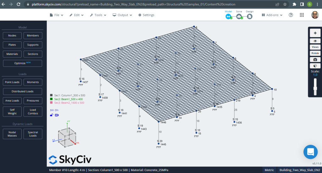
Abbildung 12. Einwegplatten in einem kleinen Gebäudebeispiel. (Strukturelles 3D, SkyCiv Cloud Engineering).
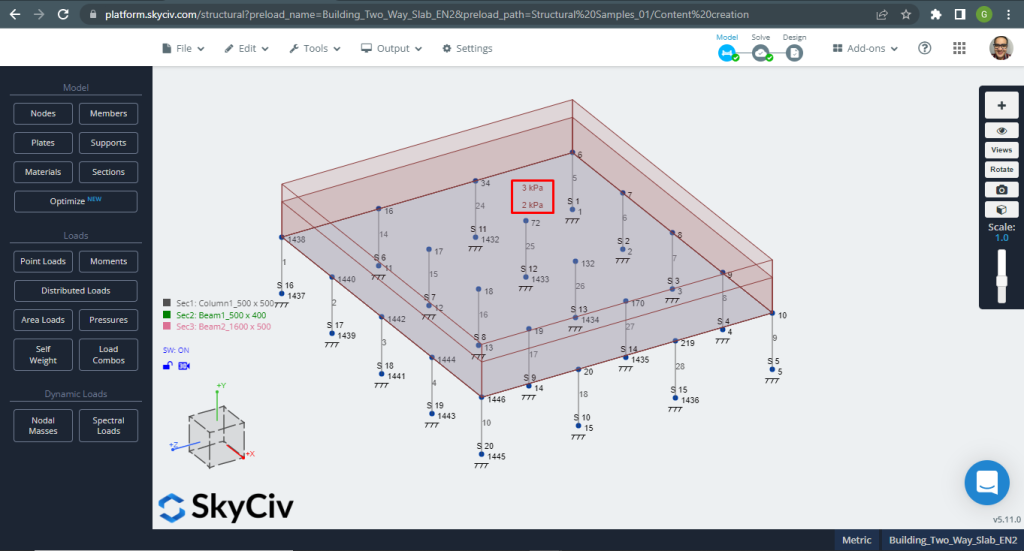
Abbildung 13. Einwegplatten in einem kleinen Gebäudebeispiel. (Strukturelles 3D, SkyCiv Cloud Engineering).
Beim Entwerfen von Platten, Wir müssen prüfen, ob die vertikale Verschiebung kleiner als das vom Code zulässige Maximum ist. Der Eurocode legt eine maximale vertikale Verschiebung der Gebrauchstauglichkeit von fest \(\frac{L.}{250}= frac{6000mm}{250}=24.0 mm\).
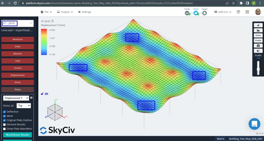
Abbildung 14. Einwegplatten in einem kleinen Gebäudebeispiel. (Strukturelles 3D, SkyCiv Cloud Engineering).
Das Bild oben zeigt uns die vertikale Verschiebung. Der Maximalwert beträgt -4,148 mm und liegt damit unter dem maximal zulässigen Wert von -24 mm. Deshalb, Die Steifigkeit der Platte ist ausreichend.
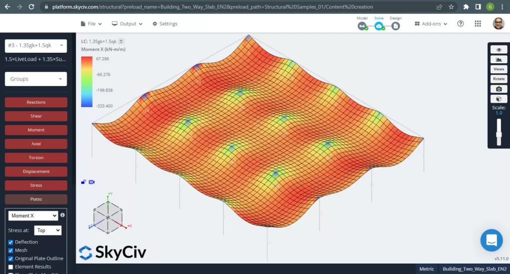
Abbildung 15. Einwegplatten in einem kleinen Gebäudebeispiel. (Strukturelles 3D, SkyCiv Cloud Engineering).
Bilder 15 und 16 bestehen aus dem Biegemoment in jeder Hauptrichtung. Nehmen Sie die Momentenverteilung und -werte, die Software, SkyCiv, kann dann die gesamte Stahlbewehrungsfläche erhalten.

Abbildung 16. Einwegplatten in einem kleinen Gebäudebeispiel. (Strukturelles 3D, SkyCiv Cloud Engineering).
Stahlverstärkungsbereiche:
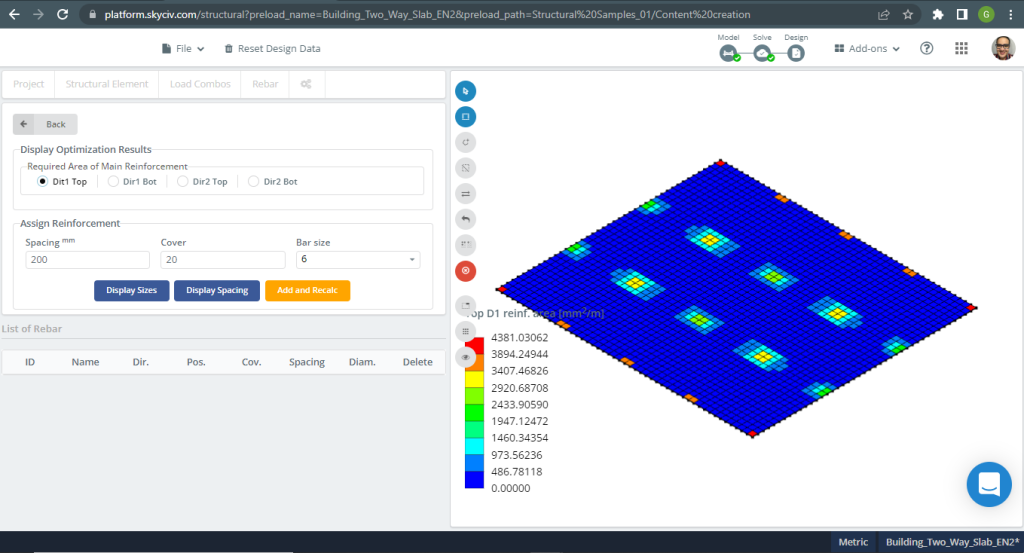
Abbildung 17. Einwegplatten in einem kleinen Gebäudebeispiel. (Strukturelles 3D, SkyCiv Cloud Engineering).
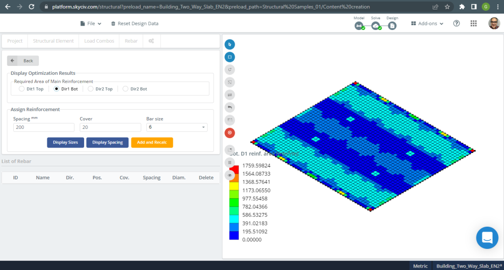
Abbildung 18. Einwegplatten in einem kleinen Gebäudebeispiel. (Strukturelles 3D, SkyCiv Cloud Engineering).
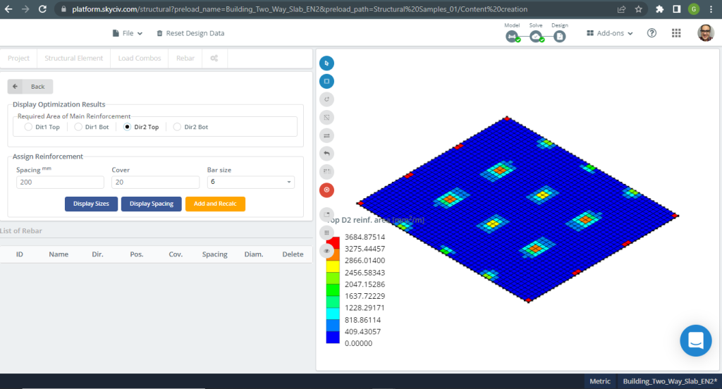
Abbildung 19. Einwegplatten in einem kleinen Gebäudebeispiel. (Strukturelles 3D, SkyCiv Cloud Engineering).
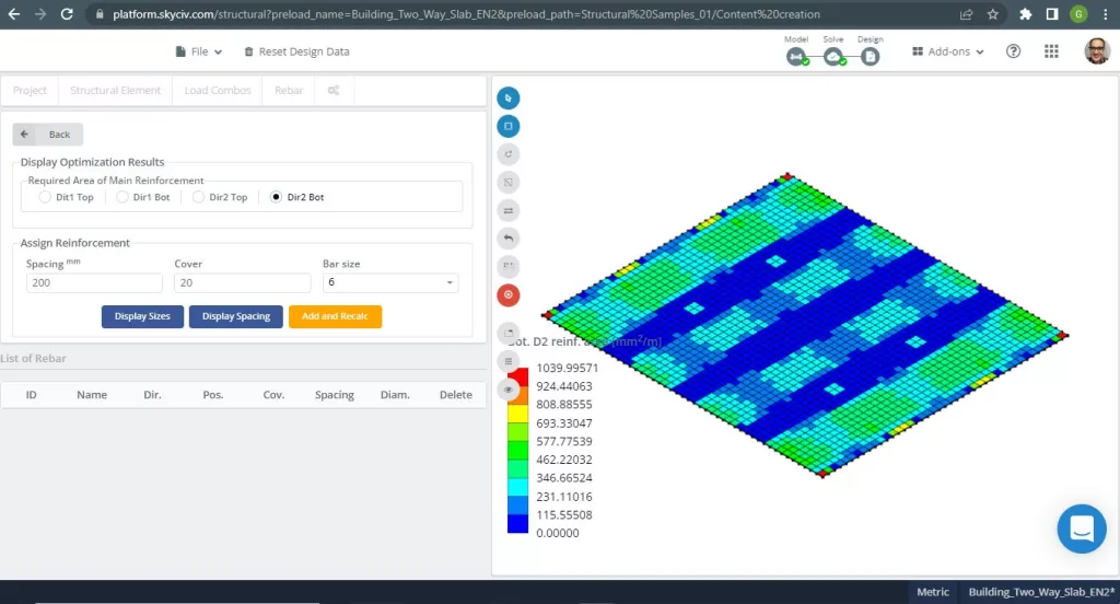
Abbildung 20. Einwegplatten in einem kleinen Gebäudebeispiel. (Strukturelles 3D, SkyCiv Cloud Engineering).
Ergebnisvergleich
Der letzte Schritt in diesem Beispiel für die bidirektionale Deckenkonstruktion besteht darin, die durch S3D-Analyse und Handberechnungen ermittelte Stahlbewehrungsfläche zu vergleichen.
Bewehrungsstahl für X-Richtung und Stützenstreifen
| Momente und Stahlbereich | Äußere negative Linke | Äußerlich positiv | Äußeres negatives Recht | Innere negative Linke | Innen positiv | Inneres negatives Recht |
|---|---|---|---|---|---|---|
| \(EIN_{st, HandCalcs} {mm^2}\) | 1498.366 | 1651.761 | 2247.55 | 2577.835 | 1651.761 | 1887.727 |
| \(EIN_{st, S3D} {mm^2}\) | 3889.375 | 1040.00 | 4196.145 | 4196.145 | 520.00 | 3175.00 |
| \(\Delta_{diff}\) (%) | 61.475 | 37.04 | 46.44 | 38.566 | 68.52 | 40.544 |
Wenn Sie neu bei SkyCiv sind, Melden Sie sich an und testen Sie die Software selbst!
Verweise
- B.. Mosley, R.. Hülse, J.H. Bungey , “Stahlbetonbemessung nach Eurocode 2”, Siebte Auflage, Palgrave MacMillan.
- Bazan Enrique & Meli Piralla, “Seismisches Design von Bauwerken”, 1ed, KLAR.
- Eurocode 2: Entwurf von Betonkonstruktionen.