SkyCiv Foundation bietet eine benutzerfreundliche Oberfläche gepaart mit einem leistungsstarken Design zur einfachen Modellierung isolierter Fundamente. In der kürzlich veröffentlichten Version 3.1, Die Benutzeroberfläche von Insulated Foundation ist unterteilt in 2 Behälter, die linke enthält 4 Registerkarten, die enthalten Einzelheiten, SkyCiv Foundation bietet a, Eingang und Ergebnisse, und das Recht enthält das 3D-Renderer.
I. Einzelheiten
Sobald der Benutzer einen Designcode ausgewählt hat, Der Benutzer kann die Projektdetails auf der aktualisieren “Einzelheiten” SkyCiv Foundation bietet a. Die Einheiten werden automatisch basierend auf dem gewählten Designcode eingestellt.
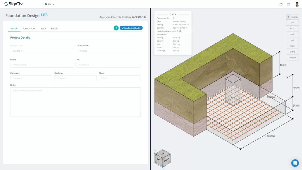
Abbildung 1. Registerkarte „Projektdetails“.
Der Benutzer kann die Informationen für die Projektdetails eingeben, wie beispielsweise
- Ein Projektname
- Eine Projekt-ID
- Ihr Firmenname
- Der Designer
- Der Kunde
- Projektnotizen (offene Notizen)
Alle Informationen werden in den generierten Designbericht eingefügt.
II. SkyCiv Foundation bietet a
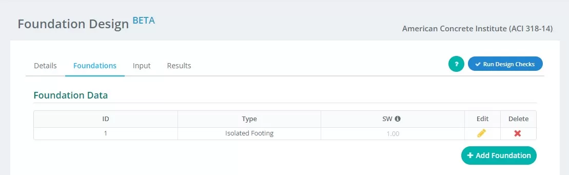
Abbildung 2. Details der Registerkarte „Grundlagen“.
Zusammenfassung der Eingaben auf der “Stiftung” Tab:
- Stiftungs-ID – Weisen Sie jedem Fundament eine numerische Identifikation zu.
- Art – In der Menüleiste auf der linken Seite “Isolierte Stiftung” aus dem Dropdown-Menü.
- SW – Eigengewichtsfaktor
- Bearbeiten – Klicken Sie hier, um mit der Eingabe von Daten zu beginnen und Ihre Stiftung zu bearbeiten
- Löschen – das Fundament löschen
III. Eingang
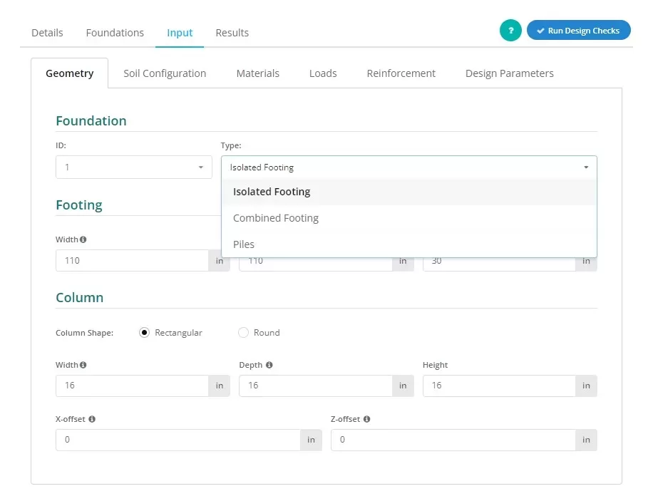
Abbildung 3. Auswahl der Isolierter Fuß im Dropdown-Menü.
Benutzer können den Fundamenttyp wie in Abbildung gezeigt festlegen 3, In der Menüleiste auf der linken Seite “Isolierter Fuß” diese Ansicht zu erwecken.
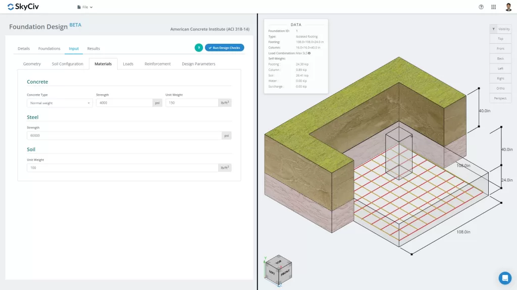
Abbildung 4. Registerkarte „Grundlage“.
Mit der “Eingang” Die Registerkarte trennt Eingabekategorien, einschließlich Geometrie, Bodenkonfiguration, Materialien, Ladungen, Verstärkung und Sonstiges. Durch diese Eingaben werden die 3D-Grafiken auf der rechten Registerkarte des Bildschirms automatisch aktualisiert. Der richtige Container wird im letzten Teil dieser Dokumentation besprochen.
Schauen wir uns die verschiedenen Eingabekategorien etwas genauer an:
Geometrie
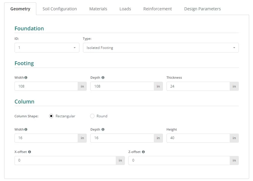
Abbildung 5. Geometrie auf der linken Registerkarte.
Siehe Abbildungen 6 und 7 für die Nomenklatur der Fundament- und Stützenabmessungen:
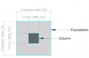
Abbildung 6. Stiftung mit Bezeichnung
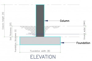
Abbildung 7. Ansicht der Stiftung
Bodenkonfiguration
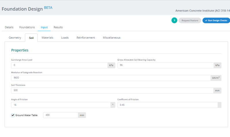
Abbildung 8. Bodenkonfiguration auf der linken Registerkarte.
Hinweis:
- Bodenwerte finden sich üblicherweise im Geotechnischen Gutachten.
- Kreuzen Sie an “Grundwasserspiegel” Feld zur Definition der Grundwasserhöhe.
- Der Wert für den Untergrundreaktionsmodul wird automatisch aktualisiert, wenn der Wert der „Bruttozulässigen Bodentragfähigkeit“ erreicht wird” ist geändert. Jedoch, Benutzer können diesen Wert weiterhin überschreiben.
Materialien
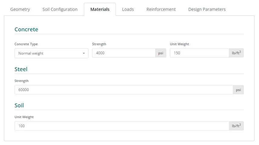
Abbildung 9. Materialien Schaltfläche auf der linken Registerkarte.
Ladungen
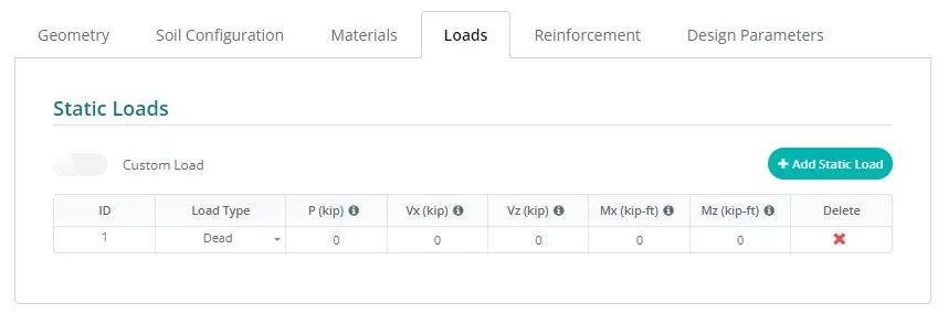
Abbildung 10. Ladungen Schaltfläche auf der linken Registerkarte.
Verstärkung
Normalerweise, Das isolierte Fundament umfasst nur Bodenverstärkungen, Eine Option für obere Verstärkungen kann jedoch durch Klicken auf die entsprechende Schaltfläche aufgerufen werden. Das Aktualisieren der Verstärkungen ist einfach, Wählen Sie in der Dropdown-Liste die Stabgröße aus und geben Sie den erforderlichen Abstand ein.
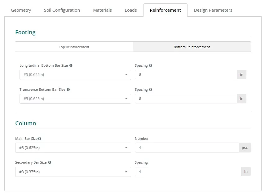
Abbildung 11. Verstärkung Schaltfläche auf der linken Registerkarte.
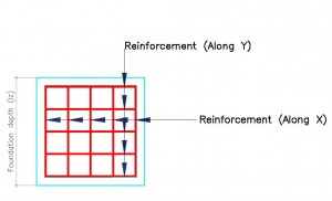
Abbildung 12. Details der Verstärkung.
Bewehrungscode-Referenz:
- ASTM615 – American Society for Testing and Materials 615 : Standardspezifikation für verformte und glatte Kohlenstoffstahlstäbe zur Betonbewehrung
- N. – Australische Bewehrungsstäbe der Klasse N
- PNS49 – Nationaler Standard der Philippinen 49 : Stahlstangen zur Betonverstärkung – Spezifikation.
- E2 – Eurocode Bewehrung P
Verschiedenes
Diese Registerkarte enthält weitere Eingaben, die für den ausgewählten Designcode erforderlich sind. Es enthält auch einige Eingaben zur Steuerung der Netzgröße des Finite-Elemente-Modells und des Durchstanzkantenfaktors für den Durchstanznachweis.
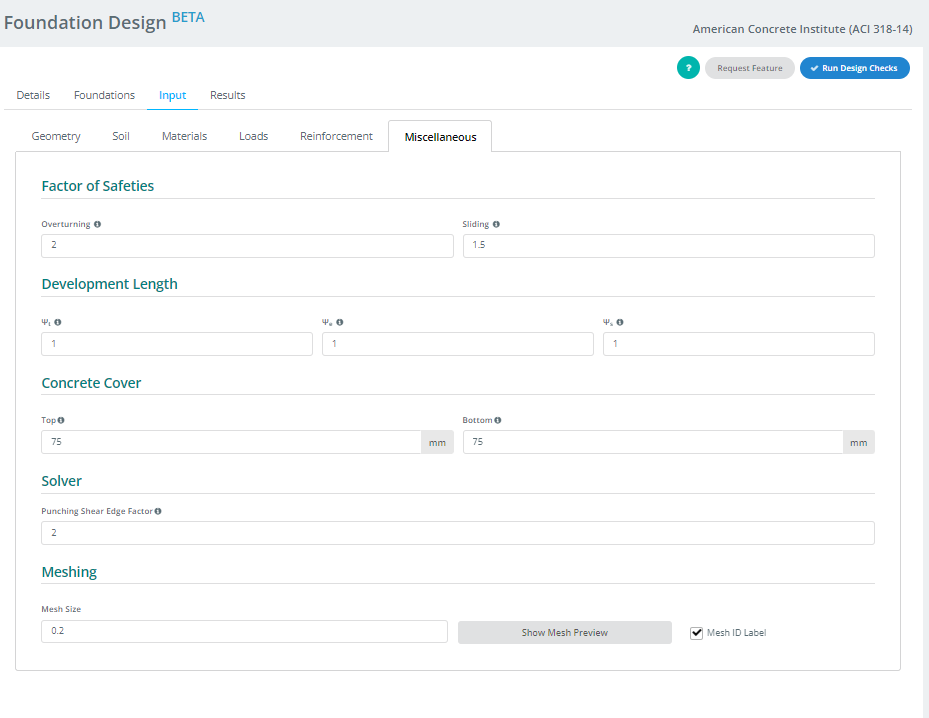
Abbildung 13. Verschiedenes Schaltfläche auf der linken Registerkarte.
IV. Ergebnisse
Ihr Entwurf erstellt die Ergebnistabelle, nachdem Sie auf die Schaltfläche „Entwurfsprüfung ausführen“ geklickt haben. Jede Spalte, bis auf die letzten beiden, stellt eine vom Foundation-Modul durchgeführte Designprüfung dar. Die Werte sind Nutzenverhältnisse; alles, was gleich oder darunter ist 1.0 ist ein PASS, und alles vorbei 1.0 ist ein FAIL. Die letzten beiden Spalten enthalten den farbcodierten Status und die Möglichkeit, auf den Bericht im HTML- oder PDF-Format zuzugreifen oder ihn herunterzuladen.
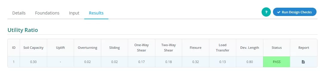
Abbildung 14. Ergebnisse Ausgabe auf der linken Registerkarte.
Zusammenfassung der Spaltendarstellungen:
- Bodendruck
Verhältnis des Bodendrucks durch erfahrene Belastungen zum zulässigen Bodendruck. - Erheben
Bestimmt, ob beim Laden Auftrieb vorhanden ist - Umkippen
Verhältnis des erlebten Kippmoments zum zulässigen Kippmoment. - Gleiten
Verhältnis der erlebten Gleitkraft zum Gleitwiderstand. - Einwegschere
Verhältnis von Einweg-Scherbedarf zu Kapazität. - Zwei-Wege-Schere
Verhältnis von ZWEI-Wege-Scherbedarf zu Kapazität. - Biegung
Verhältnis von Biegebedarf zu Biegekapazität. - Lastübertragung
Verhältnis der nominalen zur tatsächlichen Lagerfestigkeit. - Entwicklungslänge
Verhältnis der nominalen zur tatsächlichen Entwicklungslänge. - Status
Zeigt an, dass das Fundamentdesign vorhanden ist Die Hälfte der Wandhöhe von der Unterseite der Basis für den Fall des oder SCHEITERN - Bericht
Klicken Sie hier, um die detaillierte Berechnung des Fundamentdesigns anzuzeigen.
V . Renderer
zuletzt, Im rechten Teil des Bildschirms befindet sich der 3D-Renderer, der den Benutzern hilft, die Eingaben zu visualisieren. In der oberen linken Ecke befinden sich die Modellzusammenfassungsdaten mit grundlegenden Informationen über das Fundament, und in der gegenüberliegenden Ecke befinden sich die Sichtbarkeitseinstellungen. Benutzer können Objekte auswählen, die sie ein- oder ausblenden möchten, und die Ausrichtung der Grafik auswählen, die sie sehen möchten.
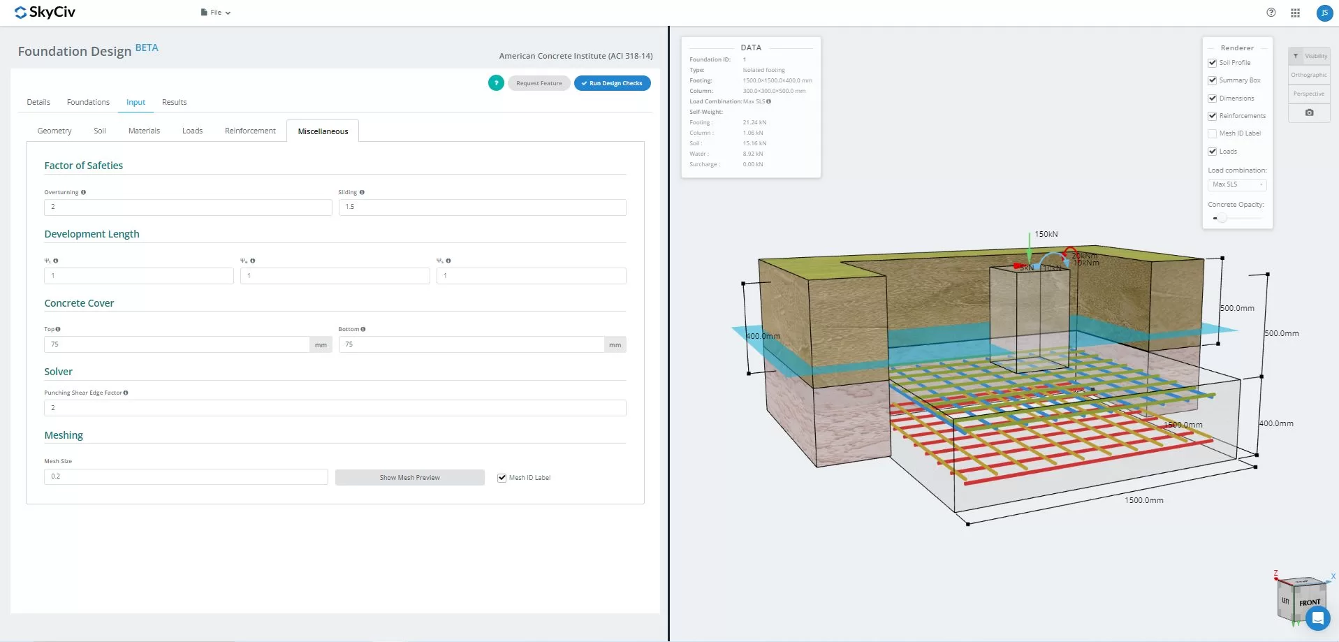
Abbildung 15.3D Grafische Darstellung des Modells
Einmal gelöst, Benutzer können die FEA-Ergebnisse des Bodendrucks anzeigen, und Holzbewaffnungsanalyse in 3D. Die Ergebnisse können über alle Lastkombinationen hinweg umgeschaltet werden, einschließlich Briefumschlägen. Ein Screenshot der aktuellen Ansicht kann ebenfalls heruntergeladen werden.
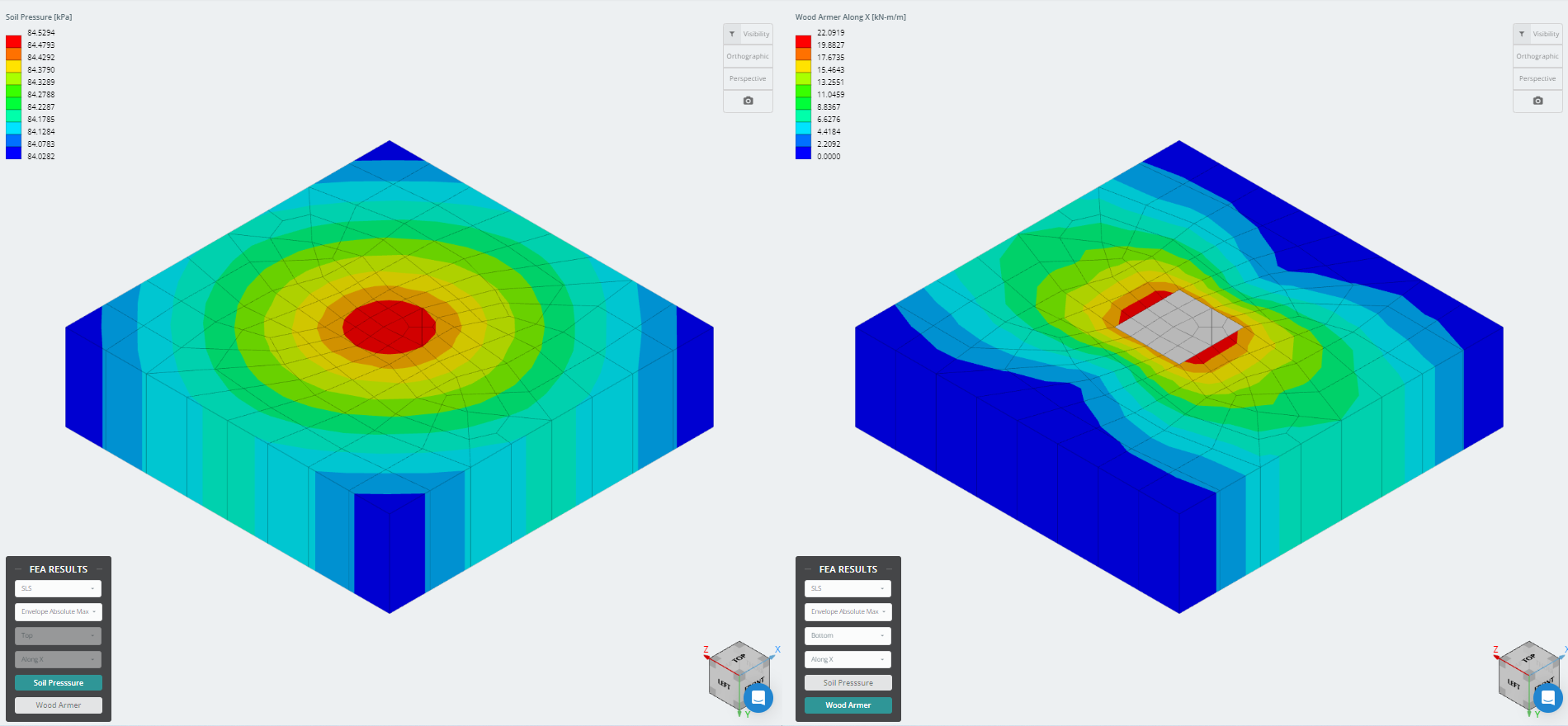
Abbildung 16. Ergebnisse der Finite-Elemente-Analyse
Möchten Sie die Foundation Design-Software von SkyCiv ausprobieren?? Mit unserem Tool können Benutzer Foundation Design-Berechnungen durchführen, ohne es herunterladen oder installieren zu müssen!
Referenz:
- Bauvorschriften für Konstruktionsbeton (ACI 318-14) Kommentar zu baurechtlichen Anforderungen an tragenden Beton (ACI 318R-14). Amerikanisches Betoninstitut, 2014.
- Taylor, Andreas, et al. The Reinforced Concrete Design Handbook: ein Begleiter zu ACI-318-14. Amerikanisches Betoninstitut, 2015.