Beispiel für Basisplatten Design mit CSA S16:19 und CSA A23.3:19
Problemanweisung
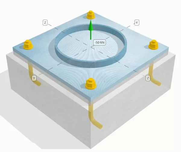
Bestimmen Sie, ob die konstruierte Säule-zu-Base-Plattenverbindung für eine Spannungsbelastung von 50 km ausreicht.
Gegebene Daten
Spalte:
Spaltenabschnitt: HS324X9.5
Säulenbereich: 9410 mm2
Säulenmaterial: 230G
Grundplatte:
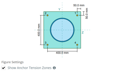
Grundplattenabmessungen: 500 mmx 500 mm
Grundplattendicke: 20 mm
Grundplattenmaterial: 230G
Fugenmörtel:
Fugenmörtel Dicke: 20 mm
Beton:
Konkrete Abmessungen: 550 mmx 550 mm
Betondicke: 200 mm
Betonmaterial: 20.68 MPa
Geknackt oder ungekrönt: Geknackt
Anker:
Ankerdurchmesser: 19.1 mm
Effektive Einbettungslänge: 130.0 mm
Hakenlänge: 60mm
Ankerversatz Abstand vom Gesicht der Säule: 120.84 mm
Schweißnähte:
Schweißtyp: CJP
Füllmetallklassifizierung: E43XX
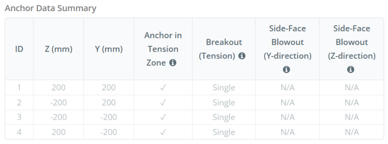
Ankerdaten (von Skyciv -Taschenrechner):
Modell im kostenlosen SkyCiv-Tool
Modellieren Sie noch heute das oben stehende Grundplattendesign mit unserem kostenlosen Online-Tool! Keine Anmeldung erforderlich.
Definitionen
Lastpfad:
Wenn eine Grundplatte einer Auftriebsausgabe ausgesetzt ist (zugfest) Kräfte, Diese Kräfte werden auf die Ankerstangen übertragen, was wiederum Biege Momente in der Grundplatte hervorruft. Die Biegeaktion kann als visualisiert werden als Beuge des Auslegers Um die Flansche oder das Netz des Spaltenabschnitts auftreten, abhängig davon, wo die Anker positioniert sind.
In dem SkyCiv Basisplatten-Design-Software, Nur Anker innerhalb der Ankerspannungszone werden als wirksam angesehen, um die Häufigkeit zu widerstehen. Diese Zone enthält typischerweise Bereiche in der Nähe der Spaltenflansche oder des Netzes. Im Fall von a Kreisspalte, Die Ankerspannungszone umfasst den gesamten Bereich außerhalb des Säulenumfangs. Anker außerhalb dieser Zone tragen nicht zum Spannungswiderstand bei und sind von den Anhebungsberechnungen ausgeschlossen.
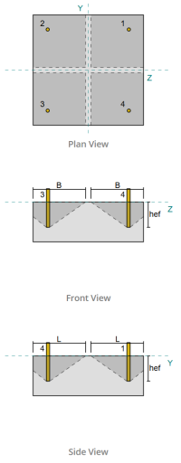
Um den effektiven Bereich der Grundplatte zu bestimmen, der sich der Biegung widersetzt, ein 45-Gradispersion wird von der Mittellinie jeder Ankerstange in Richtung der Säulenfläche angenommen. Diese Dispersion definiert die effektive Schweißlänge und hilft, die zu etablieren Effektive Biegebreite der Platte.
Die Annahme vereinfacht die Grundplattenanalyse, indem sie sich annähert, wie sich die Erhöhungskraft durch die Platte ausbreitet.
Ankergruppen:
Mit der SkyCiv Basisplatten-Design-Software Enthält eine intuitive Funktion, die identifiziert, welche Anker Teil einer Ankergruppe für die Bewertung sind Betonausbruch und Beton-Seitenflächen-Blowout Fehler.
Ein Ankergruppe besteht aus mehreren Ankern mit ähnlichen effektiven Einbettungstiefen und Abstand, und sind nah genug, dass ihre Projizierte Widerstandsbereiche überlappen sich. Wenn Anker gruppiert sind, Ihre Kapazitäten werden kombiniert, um der Gesamtspannungskraft zu widerstehen, die der Gruppe angewendet wird.
Anker, die die Gruppierungskriterien nicht erfüllen, werden als behandelt einzelne Anker. In diesem Fall, Nur die Spannungskraft am individuellen Anker wird gegen seinen eigenen wirksamen Widerstandsbereich überprüft.
Schritt-für-Schritt-Berechnungen
Prüfen #1: Berechnen Sie die Schweißkapazität
Anwenden seismischer Lasten, Wir müssen die Last pro Anker berechnen und die effektive Schweißlänge für jeden Anker bestimmen. Mit der effektive Schweißlänge basiert auf einem 45° Dispersionslinie Aus der Mitte des Ankers bis zur Säule gezeichnet. Wenn diese 45 ° -Linie die Säule nicht schneidet, bleibt die Tangentenpunkte werden stattdessen verwendet. zusätzlich, Wenn die Anker eng verteilt sind, Die effektive Schweißlänge wird reduziert, um Überlappungen zu vermeiden. Schließlich, Die Summe aller effektiven Schweißlängen darf die tatsächliche schweißbare Länge entlang des Säulenumfangs nicht überschreiten.
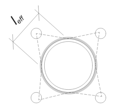
Wenden wir dies auf unser Beispiel an. Basierend auf der gegebenen Geometrie, Die 45 ° -Linie vom Anker schneidet die Säule nicht durch. Als Ergebnis, Die Lichtbogenlänge zwischen den Tangentenpunkten wird stattdessen verwendet. Diese Lichtbogenlänge muss auch alle angrenzenden Anker berücksichtigen, mit überlappenden Teilen, die abtrahiert werden, um eine Doppelzählung zu vermeiden. Die berechnete Lichtbogenlänge ist:
\(
l_{\Text{Bogen}} = 254.47 \, \Text{mm}
\)
Diese Bogenlängeberechnung ist in der Skyciv -Basisplattendesign -Software vollständig automatisiert, Es kann aber auch manuell mit trigonometrischen Methoden durchgeführt werden. Sie können das kostenlose Tool aus diesem Link ausprobieren.
Berücksichtigung der verfügbaren schweißbaren Länge entlang des Spalteumfangs der Säule, das Finale effektive Schweißlänge ist:
\(
l_{\Text{eff}} = min links( l_{\Text{Bogen}}, \frac{\pi d_{\Text{col}}}{N_{ein,t}} \richtig) = min links( 254.47 \, \Text{mm}, \frac{\pi times 324 \, \Text{mm}}{4} \richtig) = 254.47 \, \Text{mm}
\)
Als nächstes, Berechnen wir die Last pro Anker. Für einen bestimmten Satz von vier (4) Anker, Die Last pro Anker ist:
\(
T_{u,\Text{Anker}} = frac{N_x}{N_{ein,t}} = frac{50 \, \Text{kN}}{4} = 12.5 \, \Text{kN}
\)
Unter Verwendung der berechneten effektiven Schweißlänge, Wir können jetzt das berechnen Erforderliche Kraft pro Länge der Einheit auf die Schweißnaht einwirken.
\(
v_f = frac{T_{u,\Text{Anker}}}{l_{\Text{eff}}} = frac{12.5 \, \Text{kN}}{254.47 \, \Text{mm}} = 0.049122 \, \Text{kN / mm}
\)
Jetzt, Wir beziehen uns auf CSA S16:19 Klausel 13.13.3.1 um die zu berechnen berücksichtigter Widerstand der vollständigen Gelenkdurchdringung (CJP) schweißen. Dies erfordert den Basismetallwiderstand, exprimiert in Kraft pro Länge der Einheit, sowohl für die Säule als auch für die Grundplattenmaterialien.
\(
v_{r,\Text{BM}} = phi links( \min links( F_{j,\Text{col}} t_{\Text{col}}, F_{j,\Text{bp}} t_{\Text{bp}} \richtig) \richtig)
\)
\(
v_{r,\Text{BM}} = 0.9 \mal links( \min links( 230 \, \Text{MPa} \mal 9.53 \, \Text{mm}, 230 \, \Text{MPa} \mal 20 \, \Text{mm} \richtig) \richtig) = 1.9727 \, \Text{kN / mm}
\)
Schon seit 0.049122 kN / mm < 1.9727 kN / mm, Die Schweißkapazität ist ausreichend.
Prüfen #2: Berechnen Sie die Kapazität der Grundplattenflexus aufgrund der Spannungsbelastung
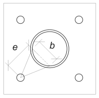
Verwenden der Last pro Anker und die Offset -Entfernung von der Mitte des Ankers bis zur Säule der Säule, Der auf die Grundplatte angewendete Moment kann mit a berechnet werden Ausleger Annahme. Für eine kreisförmige Säule, Die Last -Exzentrizität wird durch Berücksichtigung der Sagitta des geschweißten Bogens bestimmt, und kann wie folgt berechnet werden:
\(
e_{\Text{Rohr}} = d_o + r_{\Text{col}} \links( 1 – \cos links( \frac{l_{\Text{eff}}}{2 r_{\Text{col}}} \richtig) \richtig)
\)
\(
e_{\Text{Rohr}} = 120.84 \, \Text{mm} + 162 \, \Text{mm} \mal links( 1 – \cos links( \frac{254.47 \, \Text{mm}}{2 \mal 162 \, \Text{mm}} \richtig) \richtig) = 168.29 \, \Text{mm}
\)
Das induzierte Moment wird berechnet als:
\(
M_f = t_{u,\Text{Anker}} e_{\Text{Rohr}} = 12.5 \, \Text{kN} \mal 168.29 \, \Text{mm} = 2103.6 \, \Text{kN} \CDOT Text{mm}
\)
Als nächstes, Wir werden die Biegebreite der Grundplatte bestimmen. Dafür, Wir benutzen die Akkordlänge entsprechend dem effektiven Schweißbogen.
\(
\theta_{\Text{Arbeit}} = frac{l_{\Text{eff}}}{0.5 d_{\Text{col}}} = frac{254.47 \, \Text{mm}}{0.5 \mal 324 \, \Text{mm}} = 1.5708
\)
\(
B = d_{\Text{col}} \links( \Sünde links( \frac{\theta_{\Text{Arbeit}}}{2} \richtig) \richtig) = 324 \, \Text{mm} \mal links( \Sünde links( \frac{1.5708}{2} \richtig) \richtig) = 229.1 \, \Text{mm}
\)
Schließlich, Wir können die berechnen berücksichtigt Biegewiderstand der Grundplatte verwenden CSA S16:19 Klausel 13.5.
\(
M_r = phi F_{j,\Text{bp}} Z_{\Text{eff}} = 0.9 \mal 230 \, \Text{MPa} \mal 22910 \, \Text{mm}^3 = 4742.4 \, \Text{kN} \CDOT Text{mm}
\)
Wo,
\(
Z_{\Text{eff}} = frac{b (t_{\Text{bp}})^ 2}{4} = frac{229.1 \, \Text{mm} \mal (20 \, \Text{mm})^ 2}{4} = 22910 \, \Text{mm}^ 3
\)
Schon seit 2103.6 KN-MM < 4742.4 KN-MM, Die Grundkapazität der Grundplattenbiegung ist ausreichend.
Prüfen #3: Berechnen Sie die Ankerstange Zugkapazität
Bewertung der Zugkapazität der Ankerstange, Wir beziehen uns auf CSA A23.3:19 Klausel D.6.1.2 und CSA S16:19 Klausel 25.3.2.1.
Zuerst, Wir bestimmen die angegebene Zugfestigkeit des Ankerstahls. Dies ist der niedrigste Wert, der von erlaubt ist CSA A23.3:19 Klausel D.6.1.2.
\(
f_{\Text{uta}} = min links( F_{u,\Text{anc}}, 1.9 F_{j,\Text{anc}}, 860 \richtig) = min links( 400 \, \Text{MPa}, 1.9 \mal 248.2 \, \Text{MPa}, 860.00 \, \Text{MPa} \richtig) = 400 \, \Text{MPa}
\)
Als nächstes, Wir bestimmen die Wirksamer Querschnittsbereich der Verankerungsstange in der Spannung verwendet CAC Concrete Design Handbuch, 3RD Edition, Tabelle 12.3.
\(
EIN_{ich weiß,N.} = 215 \, \Text{mm}^ 2
\)
Mit diesen Werten, Wir bewerben uns CSA A23.3:19 Gl. D.2 um die zu berechnen Faktorisierter Zugwiderstand der Ankerstange.
\(
N_{\Text{Sar}} = A_{ich weiß,N.} \PHI_S F_{\Text{uta}} R = 215 \, \Text{mm}^2 mal 0.85 \mal 400 \, \Text{MPa} \mal 0.8 = 58.465 \, \Text{kN}
\)
zusätzlich, Wir bewerten die Faktorisierter Zugwiderstand entsprechend CSA S16:19 Klausel 25.3.2.1.
\(
T_r = phi_{ar} 0.85 EIN_{ar} F_{u,\Text{anc}} = 0.67 \mal 0.85 \mal 285.02 \, \Text{mm}^2 mal 400 \, \Text{MPa} = 64.912 \, \Text{kN}
\)
Nach dem Vergleich der beiden, Wir identifizieren, dass der mit CSA A23.3 berechnete faktorierte Widerstand berechnet wurde:19 regiert in diesem Fall.
Erinnern Sie sich an die zuvor berechneten Spannungsbelastung pro Anker:
\(
N_{Fa} = frac{N_x}{N_{ein,t}} = frac{50 \, \Text{kN}}{4} = 12.5 \, \Text{kN}
\)
Schon seit 12.5 kN < 58.465 kN, Die Ankerstange -Zugkapazität ist ausreichend.
Prüfen #4: Berechnen Sie die Betonausbruchkapazität in der Spannung
Vor der Berechnung der Ausbruchkapazität, Wir müssen zuerst feststellen, ob das Mitglied als qualifiziert ist enges Mitglied. Gemäß CSA A23.3:19 Klausel D.6.2.3, Das Mitglied erfüllt die Kriterien für ein schmales Mitglied nicht. Deshalb, das gegeben Effektive Einbettungslänge wird in den Berechnungen verwendet.
Verwenden von CSA A23.3:19 Gl. D.5, wir berechnen die Maximal projizierter Betonkegelbereich für einen einzelnen Anker, basierend auf der effektiven Einbettungslänge.
\(
EIN_{Merken} = 9 (h_{ef,s1})^2 = 9 \mal (130 \, \Text{mm})^2 = 152100 \, \Text{mm}^ 2
\)
Ähnlich, Wir verwenden die effektive Einbettungslänge, um die zu berechnen Tatsächlicher projizierter Betonkegelbereich des einzigen Ankers.
\(
EIN_{Nc} = L_{Nc} B_{Nc} = 270 \, \Text{mm} \mal 270 \, \Text{mm} = 72900 \, \Text{mm}^ 2
\)
Wo,
\(
L_{Nc} = left( \min links( c_{\Text{links},s1}, 1.5 h_{ef,s1} \richtig) \richtig) + \links( \min links( c_{\Text{richtig},s1}, 1.5 h_{ef,s1} \richtig) \richtig)
\)
\(
L_{Nc} = left( \min links( 475 \, \Text{mm}, 1.5 \mal 130 \, \Text{mm} \richtig) \richtig) + \links( \min links( 75 \, \Text{mm}, 1.5 \mal 130 \, \Text{mm} \richtig) \richtig)
\)
\(
L_{Nc} = 270 \, \Text{mm}
\)
\(
B_{Nc} = left( \min links( c_{\Text{oben},s1}, 1.5 h_{ef,s1} \richtig) \richtig) + \links( \min links( c_{\Text{Unterseite},s1}, 1.5 h_{ef,s1} \richtig) \richtig)
\)
\(
B_{Nc} = left( \min links( 75 \, \Text{mm}, 1.5 \mal 130 \, \Text{mm} \richtig) \richtig) + \links( \min links( 475 \, \Text{mm}, 1.5 \mal 130 \, \Text{mm} \richtig) \richtig)
\)
\(
B_{Nc} = 270 \, \Text{mm}
\)
Als nächstes, Wir bewerten die berücksichtigt Basisbeständigkeit aus Betonbreite eines einzelnen Ankers verwenden CSA A23.3:19 Gl. D.6
\(
N_{Br} = k_c phi lambda_a sqrt{\frac{f’_c}{\Text{MPa}}} \links( \frac{h_{ef,s1}}{\Text{mm}} \richtig)^{1.5} R n
\)
\(
N_{Br} = 10 \mal 0.65 \mal 1 \mal sqrt{\frac{20.68 \, \Text{MPa}}{1 \, \Text{MPa}}} \mal links( \frac{130 \, \Text{mm}}{1 \, \Text{mm}} \richtig)^{1.5} \mal 1 \mal 0.001 \, \Text{kN} = 43.813 \, \Text{kN}
\)
Wo,
- \(k_{c} = 10\) für einbetonierte Anker
- \(\lambda = 1.0 \) Für Normalgewicht Beton
Jetzt, Wir bewerten die Auswirkungen der Geometrie, indem wir die berechnen Kanteneffektfaktor.
Der kürzeste Randabstand der Ankergruppe wird als bestimmt als:
\(
c_{ein,\Text{Min.}} = min links( c_{\Text{links},s1}, c_{\Text{richtig},s1}, c_{\Text{oben},s1}, c_{\Text{Unterseite},s1} \richtig) = min links( 475 \, \Text{mm}, 75 \, \Text{mm}, 75 \, \Text{mm}, 475 \, \Text{mm} \richtig) = 75 \, \Text{mm}
\)
Gemäß CSA A23.3:19 Gl. D.10 und D.11, der Ausbruch Kanteneffektfaktor ist:
\(
\Psi_{ed,N.} = min links( 1.0, 0.7 + 0.3 \links( \frac{c_{ein,\Text{Min.}}}{1.5 h_{ef,s1}} \richtig) \richtig) = min links( 1, 0.7 + 0.3 \mal links( \frac{75 \, \Text{mm}}{1.5 \mal 130 \, \Text{mm}} \richtig) \richtig) = 0.81538
\)
Zusätzlich, beide Rissfaktor und das Spaltfaktor werden als:
\(
\Psi_{c,N.} = 1
\)
\(
\Psi_{cp,N.} = 1
\)
Dann, Wir kombinieren all diese Faktoren und verwenden ACI 318-19 Gl. 17.6.2.1b Um die zu bewerten berücksichtigt Betonausbruch Widerstand des einzigen Ankers:
\(
N_{CBR} = left( \frac{EIN_{Nc}}{EIN_{Merken}} \richtig) \Psi_{ed,N.} \Psi_{c,N.} \Psi_{cp,N.} N_{Br} = left( \frac{72900 \, \Text{mm}^ 2}{152100 \, \Text{mm}^ 2} \richtig) \mal 0.81538 \mal 1 \mal 1 \mal 43.813 \, \Text{kN} = 17.122 \, \Text{kN}
\)
Erinnern Sie sich an die zuvor berechneten Spannungsbelastung pro Anker:
\(
N_{Fa} = frac{N_x}{N_{ein,s}} = frac{50 \, \Text{kN}}{4} = 12.5 \, \Text{kN}
\)
Schon seit 12.5 kN < 17.122 kN Die Betonausbruchkapazität ist ausreichend.
Diese konkrete Ausbruchsberechnung basiert auf der Anker -ID #1. Die gleiche Kapazität gilt aufgrund des symmetrischen Designs für die anderen Anker.
Prüfen #5: Berechnen Sie die Ankerauszugskapazität
Die Ausziehkapazität eines Ankers wird durch den Widerstand an seinem eingebetteten Ende bestimmt. Für Haken Anker, Es ist abhängig von seiner Hakenlänge.
Wir berechnen die Faktorisierte grundlegende Ankerauszugswiderstand pro CSA A23.3:19 Gl. D.17.
\(
N_{pr} = Psi_{c,p} 0.9 \phi (f’_c) e_h d_a r = 1 \mal 0.9 \mal 0.65 \mal (20.68 \, \Text{MPa}) \mal 60 \, \Text{mm} \mal 19.05 \, \Text{mm} \mal 1 = 13.828 \, \Text{kN}
\)
Erinnern Sie sich an die zuvor berechneten Spannungsbelastung pro Anker:
\(
N_{Fa} = frac{N_x}{N_{ein,t}} = frac{50 \, \Text{kN}}{4} = 12.5 \, \Text{kN}
\)
Schon seit 12.5 kN < 13.828 kN, Die Ankerauszugskapazität ist ausreichend.
Prüfen #6: Berechnen Sie die Blowout-Kapazität der Seitengesicht in der y-Richtung
Diese Berechnung gilt nicht für Hakenanker.
Prüfen #7: Berechnen Sie die Blowout-Kapazität der Seitengesicht in der Z-Richtung
Diese Berechnung gilt nicht für Hakenanker.
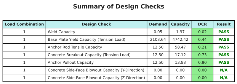
Entwurfszusammenfassung
Mit der Skyciv Base Plate Design Software kann automatisch einen Schritt-für-Schritt-Berechnungsbericht für dieses Entwurfsbeispiel erstellen. Es enthält auch eine Zusammenfassung der durchgeführten Schecks und deren resultierenden Verhältnisse, Die Informationen auf einen Blick leicht zu verstehen machen. Im Folgenden finden Sie eine Stichprobenzusammenfassungstabelle, Welches ist im Bericht enthalten.
SKYCIV -Beispielbericht
Sehen Sie sich den Detaillierungsgrad und die Klarheit an, die Sie von einem SkyCiv-Grundplatten-Designbericht erwarten können. Der Bericht umfasst alle wichtigen Designprüfungen, Gleichungen, und Ergebnisse werden in einem klaren und leicht lesbaren Format präsentiert. Es entspricht vollständig den Designstandards. Klicken Sie unten, um einen Beispielbericht anzuzeigen, der mit dem SkyCiv-Grundplattenrechner erstellt wurde.
Basisplattensoftware kaufen
Kaufen Sie die Vollversion des Basisplattendesign -Moduls Off Own anderen Skyciv -Modulen. Auf diese Weise erhalten Sie einen vollständigen Satz von Ergebnissen für die Basisplattendesign, Einbeziehung detaillierter Berichte und mehr Funktionen.