
Designbeispiel für AISC-Verbindungen
Designbeispiel für AISC-Verbindungen. Schubverbindungen between I-shaped sections are some of the most common connections in steel design. To help understand the required design checks in accordance with AISC 360-16, this article works through a design example. We can also get to the results of this example directly through the SkyCiv-Verbindungsdesign Modul. Lesen Sie unbedingt den zusätzlichen Artikel auf Entwerfen einer Momentverbindung.
A shear connection is a simple connection under AISC 360-16 B3.4. It is detailed to deliver the beam end reaction and to rotate rather than to carry end moment, which is what separates it from the moment connection covered in the companion article.
The calculations presented here use the Allowable Stress Design (ASD) Methode. Wenn Sie mit dem Unterschied zwischen ASD und LRFD in der Tragwerksplanung nicht vertraut sind, stellen Sie sicher, dass schau dir unser Video an das erklären.
Designbeispiel für AISC-Verbindungen
Für dieses Beispiel, we are going to evaluate the capacity of a single-plate connection between a W16x50 beam and a W14x90 column using the dimensions and bolts shown below. This connection needs to support the beam end reaction.
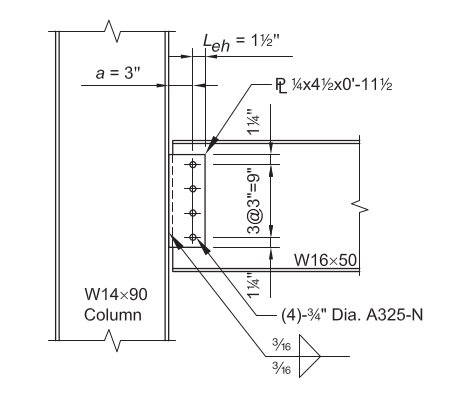
Gegeben:
Service Level Loads & Material:
Reaktion von Eigenlast (RD) = 8.0 Kips
Reaktion von Live Load (RL) = 25.0 Kips
Plattenmaterial: ASTM A36, Fy = 36 KSI, Fu = 58 KSI
Träger- und Säulenmaterial: ASTM A992, Fy = 50 KSI, Fu = 65 KSI
Balken- und Säulengeometrie:
Strahl: B16x50; tw = 0.380 im, d = 16.3 im., tf = 0.630 im
Spalte: B14x90; tf = 0.710 im.
Scherplatte: 1/4 in dick; 4 1/2 in x 11 1/2 in den Abmessungen
Mit der 11 1/2 in plate depth comes from the bolt layout: four bolts at 3 in spacing gives 9 in between the outer bolts, mehr hat 1 1/4 in edge distance top and bottom.
Vorrichtungen (Schrauben und Schweißnähte):
(4) – 3/4-im.-diameter ASTM F3125 Grade A325-N bolts in standard holes, beim 3 in spacing with 1 1/4 in edge distance
70-ksi-Elektrodenfilets. A325 und A490 sind Güten gemäß ASTM F3125, which consolidated the older standalone bolt specifications. For more on the fastener side, siehe Dokumentation unter Schrauben und Schweißnähte.
Lastberechnung:
LRFD:
Ultimative Reaktion (Ru) = 1.2(8.0 Kips) + 1.6(25.0 Kips) = 49.6 Kips
ASD:
Zulässige Reaktion (aus) = 8.0 Kips + 25 kips = 33.0 Kips
Every check below is compared against the ASD reaction of 33.0 Kips. The LRFD figure is carried only for the Manual table comparison at the end.
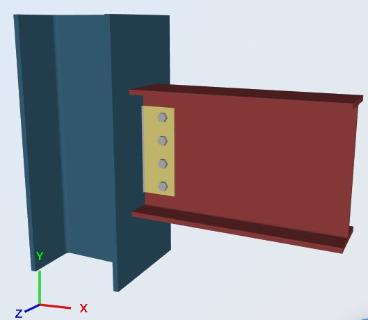
Verwenden der SkyCiv Connection Design-Software, Die verschiedenen Teile der Verbindung werden nun gemäß den Überprüfungen in Abschnitt J von AISC überprüft 360-16. The checks fall into three groups: the plate itself, the weld holding it to the column, and the bolt group joining it to the beam web.
Scherplatte, Scherausbeute
Zulässige Scherkapazität: Ω = 1.5
Rav = (0.6 Fy Agv / Ω) = [ 0.6 (36 KSI) (0.25 im) 11.5 im / 1.5 ] = 41.4 Kips
Auslegungskapazitätsverhältnis, DCR:
erforderliche Scherung, Rv = 33.0 Kips
Gesamtkapazität, Rav = 41.4 Kips
DCR = (33.0 / 41.4) = 0.797, in Ordnung
Shear Plate to W14x90 Flange, Schweißfestigkeit
Festigkeit von Kehlnähten: Ω = 2.0
Schweißnahtgröße, t = 0.1875 im
Mein Name = 0.6 FEXX [ 1.0 + 0.5 sin ^ 1.5 θ ]
θ = der Winkel, den die Last mit der Schweißachse bildet
= 90, für quer belastete Schweißnähte
= 0, für in Längsrichtung belastete Schweißnähte
Festigkeit pro Größeneinheit der Schweißnaht:
Zulässige Schweißspannung, Faw = [ 0.6 (70) / 2.0 ] = 21 KSI
Querlänge, lt = 0 im
Längslänge, ll = 23 im
effektive Gesamtlänge, l = lt (1.5) + ll (1.0) = 0 (1.5) + 23 (1.0) = 23 im
(aus / ein) = 21 KSI (23 im) = 483 Kips / im
The weld runs both sides of the plate, also die 23 in is 2 x 11.5 in and already accounts for both lines. The load runs along the weld axis here, so θ = 0 and there is no directional increase.
Effektive Größe (Kehle) der Kehlnaht, ein:
0.707 = der Kosinus oder Sinus von 45 Grad
a = (0.707) t = 0.133 im
aus = (aus / ein) ein = 483 (0.133 im) = 64.2 Kips
Auslegungskapazitätsverhältnis, DCR:
erforderliche Last, R = 33.0 Kips
Gesamtkapazität, Ra = 64.2 Kips
DCR = (33.0 / 64.2) = 0.514, in Ordnung
Scherplatte, Scherbruch
Zulässige Scherkapazität: Ω = 2.0
Berechnung der Nettotiefe:
Gesamtlänge des Bolzenlochs(s) = 0.875 im (4) = 3.5 im
Nettotiefe, dnet = 11.5 in - [ 0.875 im (4) ] = 8.0 im
Mit der 0.875 in is the 13/16 in standard hole plus the 1/16 in allowance AISC applies when computing net area.
Rav = (0.6 Fu Anv / Ω) = [ 0.6 (58 KSI) (0.25 im) 8 im / 2.0 ] = 34.8 Kips
Auslegungskapazitätsverhältnis, DCR:
erforderliche Scherung, Rv = 33.0 Kips
Gesamtkapazität, Rav = 34.8 Kips
DCR = (33.0 / 34.8) = 0.948, in Ordnung
Shear Plate at W16x50 Web, Blockscherfestigkeit blockieren
Blockscherfestigkeit: Ω = 2.0
(aus / Ω) = (Ubs Fu Ant / Ω) + Min. [ 0.6 Fy Agv , 0.6 Fu Anv ] / Ω
Block shear tears a single block out of the plate: it ruptures across the horizontal edge distance and shears down the bolt line, so a tension term and a shear term are added.
Spannungsbruchkomponente: Ubs= 1,0 (gleichmäßige Spannung)
(Ubs Fu Ant / Ω) = [ 1.0 (58 KSI) (1.0625 im) / 2.0 ] = 30.8 kips / in (0.25 im) = 7.7 Kips
Scherausgebende Komponente: 0.6 Fy Agv
(0.6 Fy Agv / Ω) = [ 0.6 (36 KSI) (10.25 im) / 2.0 ] (0.25) = 110.7 kips / in (0.25 im) = 27.7 Kips
Scherbruchkomponente: 0.6 Fu Anv
(0.6 Fu Anv / Ω) = [ 0.6 (58 KSI) (7.1875 im) / 2.0 ] (0.25 im) = 125.1 kips / in (0.25 im) = 31.3 Kips
Gesamtblockscherkapazität:
(aus / Ω)= 7.7 Kips + Min. [ 27.7 Kips , 31.3 Kips ] = 35.4 Kips
Auslegungskapazitätsverhältnis, DCR:
erforderliche Scherung, Rv = 33.0 Kips
Gesamtkapazität, Rav = 35.4 Kips
DCR = (33.0 / 35.4) = 0.933, in Ordnung
Shear Plate at W16x50 Web, Scher- und Lagerprüfung der Schraubengruppe
1. Scherfestigkeit der Schrauben: Ω = 2.0
Designbeispiel für AISC-Verbindungen 0.768 im
Nennscherfestigkeit, Fnv = 54 KSI
Nennscherfestigkeit (pro Schraube), Rnv = Fnv Ab = (54 KSI) 0.463 Designbeispiel für AISC-Verbindungen 25.0 Kips
(Rnv / Ω) = 12,5 Kips / Bolzen
Mit der 54 ksi is the nominal shear stress for a Grade A325 bolt with threads included in the shear plane, taken straight from AISC Table J3.2, so no further reduction is applied to it.
2. Lagerfestigkeit von Standardschraubenlöchern: Ω = 2.0
(Ignorieren der Verformung der Schraubenlöcher bei Betriebslast)
clear distance at the edge bolt, lc = 0.84 im (von dem 1 1/4 in edge distance less half a hole)
clear distance to adjacent hole, lc = 2.19 im (von dem 3 in spacing less one hole)
The edge bolt has the smaller clear distance, so it controls:
(Rnb / Ω) = (1.5 lc t Fu / Ω) ≤ (3.0 d t Fu / Ω)
Because hole deformation is not taken as a design consideration here, der AISC 360-16 J3-6b coefficients of 1.5 und 3.0 apply rather than the 1.2 und 2.4 of J3-6a.
Für die äußere Schraube (herausreißen), lc = 0.84 im:
Rnb = 1.5 lc t Fu =1,5 (0.84 im) 0.25 im (58 KSI) = 18.4 Kips
(Rnb / Ω) = 9.2 Kips
Für den inneren Bolzen (herausreißen), lc = 2.19 im:
Rnb = 1.5 lc t Fu = 1.5 (2.19 im) 0.25 im (58 KSI) = 47.6 Kips
(Rnb / Ω) = 23.8 Kips
Für das Gesamtlager (Bolzenlochverlängerung):
Rnb = 3.0 Designbeispiel für AISC-Verbindungen Fu = 3.0 (0.768 im) 0.25 im (58 KSI) = 33.4 Kips
(Rnb / Ω) = 16.7 Kips
Das Lager kontrolliert seitdem die Bolzenscherung 9.2 Kips < 12.5 Kips
3. Kapazität der Bolzengruppe
Betrachtet man das Minimum unter: Bolzenscherkapazität, Lager und Einreißen in inneren und äußeren Schraubenlöchern.
ein). Kapazität der äußeren Schraube (wie oben festgelegt):
(äußere Schraube) , Rab = 9.2 Kips / Bolzen
b). Kapazität der inneren Schraube (wie oben festgelegt):
(innere Schraube) , Rab = 12.5 Kips / Bolzen
c). Kapazität der Schrauben als Gruppe: one outer bolt plus three inner bolts
Rab = 1 (9.2 Kips / Bolzen) + 3 (12.5 Kips / Bolzen) = 46.7 Kips
Auslegungskapazitätsverhältnis, DCR:
erforderliche Scherung, R = 33.0 Kips
Gesamtkapazität, Rab = 46.7 Kips
DCR = (33.0 / 46.7) = 0.707, in Ordnung
Beam Web, Scherbruch (B16x50)
Zulässige Scherkapazität: Ω = 2.0
Berechnung der Nettotiefe:
Gesamtlänge des Bolzenlochs(s) = 0.875 im (4) = 3.5 im
Nettotiefe, dnet = 16,3 - [ 0.875 im (4) ] = 12.8 im
Rav = (0.6 Fu Anv / Ω) = [ 0.6 (58 KSI) (0.38 im) 12.8 / 2.0 ] = 84.6 Kips
Auslegungskapazitätsverhältnis, DCR:
erforderliche Scherung, Rv = 33.0 Kips
Gesamtkapazität, Rav = 84.6 Kips
DCR = (33.0 / 84.6) = 0.390, in Ordnung
Beam Web, Scher- und Lagerprüfung der Schraubengruppe
1. Scherfestigkeit der Schrauben: Ω = 2.0
Designbeispiel für AISC-Verbindungen 0.768 im
Nennscherfestigkeit, Fnv = 54 KSI
Nennscherfestigkeit (pro Schraube), Rnv = Fnv Ab = (54 KSI) 0.463 Designbeispiel für AISC-Verbindungen 25.0 Kips
(Rnv / Ω) = 12,5 Kips
2. Lagerfestigkeit von Standardschraubenlöchern: Ω = 2.0
(Ignorieren der Verformung der Schraubenlöcher bei Betriebslast)
clear distance at the edge bolt, lc = 0.84 im
clear distance to adjacent hole, lc = 2.19 im
The edge bolt has the smaller clear distance, so it controls.
(Rnb / Ω) = (1.5 lc t Fu / Ω) ≤ (3.0 d t Fu / Ω)
Für die äußere Schraube (herausreißen), lc = 0.84 im:
Rnb = 1.5 lc t Fu = 1.5(0.84 im) 0.38 im (58 KSI) = 27.9 Kips
(Rnb / Ω) = 13.9 Kips
Für den inneren Bolzen (herausreißen), lc = 2.19 im:
Rnb = 1.5 lc t Fu = 1.5 (2.19 im) 0.38 im (58 KSI) = 72.3 Kips
(Rnb / Ω) = 36.2 Kips
Für das Gesamtlager (Bolzenlochverlängerung):
Rnb = 3.0 Designbeispiel für AISC-Verbindungen Fu = 3.0 (0.768 im) 0.38 im (58 KSI) = 50.8 Kips
(Rnb / Ω) = 25.4 Kips
Die Bolzenscherung kontrolliert seitdem das Lager 12.5 Kips < 13.9 Kips
Note that the beam web is thicker than the plate at 0.380 in against 0.250 im, so every bearing value here is larger and the bolts themselves become the limit. The plate, being the thinner part, is where bearing governs.
3. Kapazität der Bolzengruppe
Betrachtet man das Minimum unter: Bolzenscherkapazität, Lager und Einreißen in inneren und äußeren Schraubenlöchern.
ein). Kapazität der äußeren Schraube (wie oben festgelegt):
(äußere Schraube), Rab = 12.5 Kips / Bolzen
b). Kapazität der inneren Schraube (wie oben festgelegt):
(innere Schraube), Rab = 12.5 Kips / Bolzen
c). Kapazität der Schrauben als Gruppe: one outer bolt plus three inner bolts
Rab = 12.5 Kips + 3(12.5 Kips) = 50.0 Kips
Auslegungskapazitätsverhältnis, DCR:
erforderliche Scherung, R = 33.0 Kips
Gesamtkapazität, Rab = 50.0 Kips
DCR = (33.0 / 50.0) = 0.660, in Ordnung
Every check passes. Plate shear rupture governs at 0.948, with block shear close behind at 0.933, and both are properties of the 1/4 in plate. If this reaction grew, a thicker plate would buy the most capacity for the least work.

Alternative, wenn Sie bereits ein erfahrener Ingenieur sind und mit dem Konstruktionsprozess für eine einfache Scherverbindung vertraut sind, Der Prozess kann erheblich verkürzt werden, thanks to the design tables offered in the AISC Steel Construction Manual:
Bolzenschere, Schweißschere, und Bolzenlager, Scherausbeute, Scherbruch, und Blockscherbruch der Platte
Versuchen Sie es mit vier Schraubenreihen, 1/4-im. Plattendicke, und 3/16-in. Kehlnahtgröße.
Aus dem AISC-Handbuch Tabelle 10-10a:
LRFD
PhiRn = 52.2 Kips > 49.6 kips = Ru, in Ordnung
ASD
R.n / Ω = 34.8 Kips > 33.0 kips = Ra, in Ordnung
The table returns the same 34.8 kips that the long-hand plate shear rupture check gave above, which is the check that governs the plate.
Bolzenlager für Trägerbahn
Blockscherbruch, Scherfestigkeit und Scherbruch werden für einen nicht bewältigten Abschnitt nicht kontrolliert.
Aus der AISC-Handbuchtabelle 10-1, für einen nicht bewältigten Abschnitt, Die verfügbare Stärke der Balkenbahn beträgt:
LRFD
PhiR.n = 351 kips / in. (0.380 im.) = 133 Kips > 49.6 kips = Ru, in Ordnung
ASD
R.n / Ω = 234 kips / in. (0.380 im.) = 88.9 Kips > 33.0 kips = Ra, in Ordnung
Designbeispiel für AISC-Verbindungen (Die PDF-Version finden Sie hier: ASD Connection Design Report.pdf ). Ähnlich, Das LRFD-Versionsbeispiel finden Sie unter diesem Link: LRFD Connection Design.pdf.
Run This Example Yourself
Enter the W16x50, the W14x90 and the 1/4 in plate, and the module returns every check above with its utilization ratio and the clause behind it. Es läuft im Browser, ohne dass es etwas zu installieren gibt.

VERWEISE:
AISC 360-16, Spezifikation für Baustahlgebäude
AISC-Stahlkonstruktionshandbuch, Tabellen 10-1 and 10-10a
AISC-Entwurfsbeispiele v14.1 (BEISPIEL II.A-17, Seiten IIA-60 bis 61)
SkyCiv Connection Design Software: https://skyciv.com/structural-software/connection-design/
Single plate connection calculator: https://skyciv.com/structural-software/connection-design/single-plate-connection-calculator/
