
Wenn Sie unseren vorherigen Artikel gelesen haben, AISC 360: Scherverbindungsdesign, you would have a good sense of how simple connections are designed under AISC 360. A shear connection only has to deliver the beam end reaction. A moment connection has to deliver that reaction and the end moment with it, which brings the supporting column into the problem. In this article we work through an example moment connection between two I-shaped members and go through the design criteria that have to be satisfied. We can also get to the same results directly through the SkyCiv-Verbindungsdesign Modul, which checks these connections to AISC 360-16 in ASD oder LRFD.
As in the shear connection example, the calculations here use the Allowable Stress Design (ASD) Methode. Wenn Sie mit dem Unterschied zwischen ASD und LRFD in der Tragwerksplanung nicht vertraut sind, stellen Sie sicher, dass schau dir unser Video an das erklären.
In diesem Beispiel, we evaluate the capacity of a Bolted Flange-Plated Fully-Restrained (NS) Moment connection between a W18x50 beam and a W14x99 column, using the dimensions, welds and loads shown below. The connection has to support the beam end vertical reaction and the developed end moment. Compared with a shear connection, the difference is the pair of plates carrying the beam flange forces onto the supporting column flange.
The flange plates turn the beam end moment into a tension and compression couple. The top plate pulls, the bottom plate pushes, and both forces land on the column flange as concentrated forces. That is why a moment connection needs the column local checks that a shear connection does not.
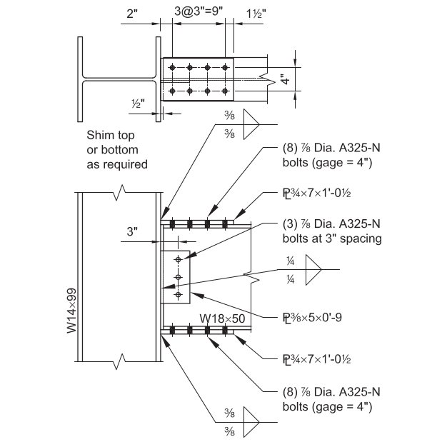
Gegeben:
Service Level Loads & Material:
Vertikale Scherung durch Eigenlast (VD) = 7.0 Kips
Vertikale Scherung durch Nutzlast (VL) = 21.0 Kips
Moment von Dead Load (MD) = 42.0 kip-ft
Moment von Live Load (ML) = 126.0 kip-ft
Plattenmaterial: ASTM A36, Fy = 36 KSI, Fu = 58 KSI
Träger- und Säulenmaterial: ASTM A992, Fy = 50 KSI, Fu = 65 KSI
Balken- und Säulengeometrie:
Strahl: B18x50; bf = 7.50 im, tf = 0.570 im, d = 18.0 im, tw = 0.355 im, Sx = 88.9 in^3
Spalte: B14x99; bf = 14.6 im, tf = 0.780 im, d = 14.2 im, tw = 0.485 im, kdes = 1.38 im
Flanschplatte: 3/4 in dick; 7.0 in x 12.5 in den Abmessungen
Stegplatte: 3/8 in dick; 5.0 in x 9.0 in den Abmessungen
Vorrichtungen (Schrauben und Schweißnähte):
Flansch: (8) – 7/8-im.-diameter ASTM F3125 Grade A325-N bolts in standard holes
Stegplatte: (3) – 7/8-im.-diameter ASTM F3125 Grade A325-N bolts in standard holes
70-ksi-Elektrodenfilets. A325 und A490 sind Güten gemäß ASTM F3125, which consolidated the older standalone bolt specifications.
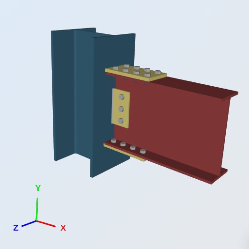
Lastberechnungen:
LRFD Ladungen (Nur Referenz):
Ultimative vertikale Reaktion (R.u) = 1.2 (7.0 Kips) + 1.6 (21.0 Kips) = 42.0 Kips
Ultimativer Moment (M.u) = 1.2 (42.0 kip-ft) + 1.6 (126.0 kip-ft) = 252.0 kip-ft
ASD Ladungen:
Zulässige vertikale Reaktion (R.ein) = 7.0 Kips + 21 kips = 28.0 Kips
Zulässiger Moment (M.ein) = 42.0 kip-ft + 126 kip-ft = 168.0 kip-ft
Everything below is checked against the ASD loads. Keep the two methods apart: ASD compares service loads to allowable strength, LRFD compares factored loads to design strength, and the LRFD figures above are carried only so you can compare the two.
Lösung basierend auf der SkyCiv Connection Design Software:
ERRATUM: Die Flanschplattenbreite in diesem Beispiel war 7.0 im aber die in den Berechnungen verwendete Breite ist 7.50 im, daher der Unterschied in den Werten.
Flanschkraft
Every check that follows is driven by one number, the force in the flange plate. The end moment is resolved into a couple acting at the plate centroids, so the lever arm is the beam depth plus one plate thickness:
P.von = [ 168.0 kip-ft (12 in/ft) ] / (18.0 im + 0.75 im) = 107.5 Kips
Flanschplatte zu W14x99 Flansch, Schweißfestigkeit
Festigkeit von Kehlnähten, Ω = 2.0
Schweißnahtgröße, t = 0.375 im
F.nw = 0.6 F.EXX [ 1.0 + 0.5 ohne1.5 (θ) ]
Wo, θ = der Winkel, den die Last mit der Schweißnahtachse bildet
= 90, für quer belastete Schweißnähte
= 0, für in Längsrichtung belastete Schweißnähte
Festigkeit pro Größeneinheit der Schweißnaht:
Zulässige Schweißspannung, F.aw = 0.6 (70KSI) / 2.0 = 21 KSI
Querlänge, lt = 7 im
Längslänge, ll = 0 im
effektive Gesamtlänge, l = lt (1.5) + ll (1.0) = 10.5 im
Mit der 1.5 on the transverse length is the directional strength increase, 1.0 + 0.5 ohne1.5(90).
(R.ein / ein) = 21 KSI (10.5 im) = 220.5 Kips / im
Effektive Größe (Kehle) der Kehlnaht, ein:
0.707 = Kosinus oder Sinus von 45 Grad
a = (0.707) t = 0.265 im
Two welds, one each side of the plate:
R.ein = (R.ein / ein) ein (2) = 220.50 (0.265 im) 2 = 116.9 Kips
Auslegungskapazitätsverhältnis, DCR:
erforderliche Last, R = 107.5 Kips
Gesamtkapazität, R.ein = 116.9 Kips
DCR = (107.5 / 116.9) = 0.919, in Ordnung
Spalte Lokale Prüfungen
These four checks ask whether the W14x99 can accept the flange force without local stiffening. All of them are compared against the same flange force:
Flanschkraft, P.von = 107.5 Kips
- Lokaler Webertrag, Ω = 1.5
R.n / Ω = [ F.ist tw (5k + lb) ] / Ω = 50ksi (0.485im) [ 5(1.38im) + 0.75im ] / 1.5 = 123.7 Kips
Hier tw is the column web thickness and lb the bearing length, taken as the flange plate thickness.
Auslegungskapazitätsverhältnis, DCR:
Flanschkraft, P.von = 107.5 Kips
Gesamtkapazität, R.ein = 123.7 Kips
DCR = (107.5 / 123.7) = 0.869, in Ordnung
- Flansch lokales Biegen, Ω = 1.67
R.n / Ω = [ 6.25 F.j tf2 ] / Ω = [ 6.25 (50KSI) (0.78im)2 ] / 1.67 = 113.8 Kips
Auslegungskapazitätsverhältnis, DCR:
Flanschkraft, P.von = 107.5 Kips
Gesamtkapazität, R.ein = 113.8 Kips
DCR = (107.5 / 113.8) = 0.944, in Ordnung
- Lokale Verkrüppelung im Web, Ω = 2.0
R.n / Ω = 0.8 tw2 [ 1 + 3 ( lb / d ) ( tw / tf )1.5 ] ( E Fj tf / tw)0.5 / Ω
= 0.8 (0.485im)2 [ 1 + 3 (0.05) (0.62)1.5 ] [ (29000KSI) (50KSI) (0.78im) / 0.485im ] 0.5 / 2.0
= 154.8 Kips
Auslegungskapazitätsverhältnis, DCR:
Flanschkraft, P.von = 107.5 Kips
Gesamtkapazität, R.ein = 154.8 Kips
DCR = (107.5 / 154.8) = 0.694, in Ordnung
- Web-Kompressionsknicken, Ω = 1.67
R.n / Ω = [ 24 tw3 ( E Fj )0.5 / h ] / Ω
= 24 (0.485im)3 [ (29000KSI) (50KSI) ] 0.5 / 14.2im (1.67)
= 139.0 Kips
The full column depth is used here in place of h, the clear distance between flanges less the fillets, was konservativ ist.
Auslegungskapazitätsverhältnis, DCR:
Flanschkraft, P.von = 107.5 Kips
Gesamtkapazität, R.ein = 139.0 Kips
DCR = (107.5 / 139.0) = 0.773, in Ordnung
None of the four column local checks governs, so the W14x99 takes the flange force without transverse stiffeners for these limit states. Had any of them exceeded 1.0, the fix would be stiffeners or a doubler plate rather than a larger flange plate, because the capacity that ran out belongs to the column.
W18x50 Flansch, Nachgiebigkeit der Flanschplatte
Stärke des Elements in Spannung, Ω = 1.67
R.n / Sie stellen nicht die gleiche Designherausforderung wie Momentverbindungenj EinG / Ω = (36KSI) (7.5im) (0.75im) / 1.67 = 121.3 Kips
Auslegungskapazitätsverhältnis, DCR:
Flanschkraft, P.von = 107.5 Kips
Gesamtkapazität, R.ein = 121.3 Kips
DCR = (107.5 / 121.3) = 0.887, in Ordnung
W18x50 Flansch, Nachgiebigkeit der Flanschplatte
Stärke des Elements in Kompression, Ω = 1.67
R.n / Sie stellen nicht die gleiche Designherausforderung wie Momentverbindungenj EinG / Ω = (36KSI) (7.5im) (0.75im) / 1.67 = 121.3 Kips
The compression plate is checked on the gross section because the bolt holes are filled in bearing. It matches the tension yielding value because the plate is short enough between the column face and the first bolt line for slenderness not to reduce it.
Auslegungskapazitätsverhältnis, DCR:
Flanschkraft, P.von = 107.5 Kips
Gesamtkapazität, R.ein = 121.3 Kips
DCR = (107.5 / 121.3) = 0.887, in Ordnung
W18x50 Flansch, Flanschplattenzugbruch
Stärke des Elements im Bruch, Ω = 2.0
Scherverzögerungsfaktor, U. aus AISC-Spezifikationstabelle D3.1: 1.0
R.n / Sie stellen nicht die gleiche Designherausforderung wie Momentverbindungenu Eine / Ω = (58KSI) [ 7.5im – 2 (1im) ] (0.75im) (1.0) / 2.0 = 119.6 Kips
Two holes are deducted across the plate width. Mit der 1 in deduction is the 7/8 in bolt diameter plus 1/8 im, which is the standard hole allowance used for net area.
Auslegungskapazitätsverhältnis, DCR:
Flanschkraft, P.von = 107.5 Kips
Gesamtkapazität, R.ein = 119.6 Kips
DCR = (107.5 / 119.6) = 0.899, in Ordnung
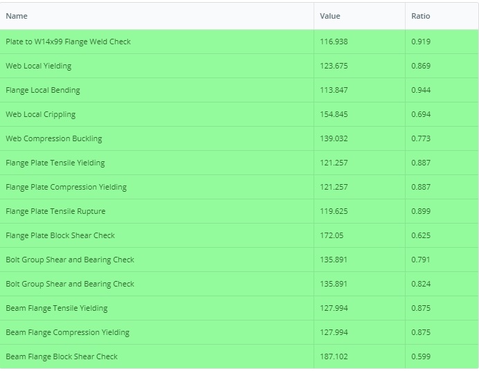
Übersichtstabelle aller Ergebnisprüfungen
Nachfolgend finden Sie die Übersichtstabelle des SkyCiv-Verbindungsdesignmoduls mit allen erforderlichen Designprüfungen, die für diese Verbindung durchgeführt wurden. Nicht alle dieser Schecks wurden in diesem Artikel gezeigt, aber sie sind als PDF verfügbar, das Sie hier herunterladen können: Anschluss-Design-Bericht-BEISPIEL II.B-1-ASD
Of the checks worked through above, flange local bending governs at 0.944. That is the one to watch if the beam end moment grows, and it is a column property, so a heavier flange plate would not help.
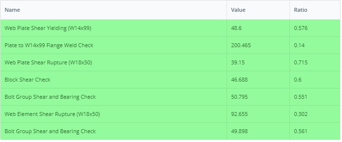
Ähnlich, Das LRFD-Versionsbeispiel finden Sie unter diesem Link: Anschluss-Design-Bericht-BEISPIEL II.B-1-LRFD
Run This Example Yourself
Enter the W18x50, the W14x99 and the flange plates, and the module returns every check above with its utilization ratio and the clause behind it. Es läuft im Browser, ohne dass es etwas zu installieren gibt.

Verweise
- AISC 360-16, Spezifikation für Baustahlgebäude
- AISC-Entwurfsbeispiele v14.1 (BEISPIEL II.B-1, Seiten IIB-2 bis 13)
- SkyCiv Connection Design Software: https://skyciv.com/structural-software/connection-design/
- Flange plate connection calculator: https://skyciv.com/structural-software/connection-design/flange-plate-connection-calculator/
