
AISC Connection Design Example
This tutorial provides an AISC connection design example. Shear connections between I-shaped sections are some of the most common connections in steel design. To help understand the required design checks in accordance with AISC 360-16, this article works through a design example. We can also get to the results of this example directly through the SkyCiv Connection Design module. Make sure to check out the additional article on designing a moment connection.
A shear connection is a simple connection under AISC 360-16 B3.4. It is detailed to deliver the beam end reaction and to rotate rather than to carry end moment, which is what separates it from the moment connection covered in the companion article.
The calculations presented here use the Allowable Stress Design (ASD) method. If you aren’t familiar with the difference between ASD and LRFD in structural design, make sure to check out our video explaining this.
AISC Connection Design Manual
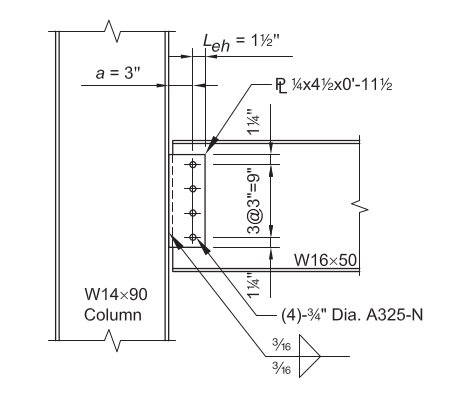
For this example, we are going to evaluate the capacity of a single-plate connection between a W16x50 beam and a W14x90 column using the dimensions and bolts shown below. This connection needs to support the beam end reaction.
Given:
Service Level Loads & Material:
Reaction from Dead Load (RD) = 8.0 kips
Reaction from Live Load (RL) = 25.0 kips
Plate Material: ASTM A36, Fy = 36 ksi, Fu = 58 ksi
Beam and Column Material: ASTM A992, Fy = 50 ksi, Fu = 65 ksi
Beam and Column Geometry:
Beam: W16x50; tw = 0.380 in, d = 16.3 in., tf = 0.630 in
Column: W14x90; tf = 0.710 in.
Shear Plate: 1/4 in thick; 4 1/2 in x 11 1/2 in dimensions
The 11 1/2 in plate depth comes from the bolt layout: four bolts at 3 in spacing gives 9 in between the outer bolts, plus a 1 1/4 in edge distance top and bottom.
Fixtures (Bolts and Welds):
(4) – 3/4-in.-diameter ASTM F3125 Grade A325-N bolts in standard holes, at 3 in spacing with 1 1/4 in edge distance
70-ksi electrode fillets. A325 and A490 are grades within ASTM F3125, which consolidated the older standalone bolt specifications. For more on the fastener side, see the documentation on bolts and welds.
Load Calculation:
LRFD:
Ultimate Reaction (Ru) = 1.2(8.0 kips) + 1.6(25.0 kips) = 49.6 kips
ASD:
Allowable Reaction (Ra) = 8.0 kips + 25 kips = 33.0 kips
Every check below is compared against the ASD reaction of 33.0 kips. The LRFD figure is carried only for the Manual table comparison at the end.
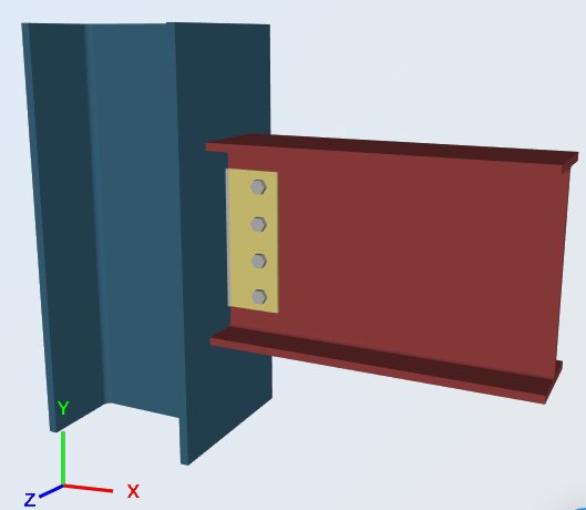
Using the SkyCiv Connection Design software, the different parts of the connection will now be checked in accordance with the Section J checks of AISC 360-16. The checks fall into three groups: the plate itself, the weld holding it to the column, and the bolt group joining it to the beam web.
Shear Plate, Shear Yielding
Allowable Shear Capacity: Ω = 1.5
Rav = (0.6 Fy Agv / Ω) = [ 0.6 (36 ksi) (0.25 in) 11.5 in / 1.5 ] = 41.4 kips
Design capacity ratio, DCR:
required shear, Rv = 33.0 kips
overall capacity, Rav = 41.4 kips
DCR = (33.0 / 41.4) = 0.797, OK
Shear Plate to W14x90 Flange, Weld Strength
Strength of Fillet Welds: Ω = 2.0
Weld Size, t = 0.1875 in
Fnw = 0.6 FEXX [ 1.0 + 0.5 sin^1.5 θ ]
θ = the angle which the load makes with the weld axis
= 90, for transversely loaded welds
= 0, for longitudinally loaded welds
Strength per unit size of weld:
Allowable weld stress, Faw = [ 0.6 (70) / 2.0 ] = 21 ksi
transverse length, lt = 0 in
longitudinal length, ll = 23 in
total effective length, l = lt (1.5) + ll (1.0) = 0 (1.5) + 23 (1.0) = 23 in
(Ra / a) = 21 ksi (23 in) = 483 kips / in
The weld runs both sides of the plate, so the 23 in is 2 x 11.5 in and already accounts for both lines. The load runs along the weld axis here, so θ = 0 and there is no directional increase.
Effective size (throat) of fillet weld, a:
0.707 = the cosine or sine of 45deg
a = (0.707) t = 0.133 in
Ra = (Ra / a) a = 483 (0.133 in) = 64.2 kips
Design capacity ratio, DCR:
required load, R = 33.0 kips
overall capacity, Ra = 64.2 kips
DCR = (33.0 / 64.2) = 0.514, OK
Shear Plate, Shear Rupture
Allowable Shear Capacity: Ω = 2.0
Calculation of net depth:
total length of bolt hole(s) = 0.875 in (4) = 3.5 in
net depth, dnet = 11.5 in − [ 0.875 in (4) ] = 8.0 in
The 0.875 in is the 13/16 in standard hole plus the 1/16 in allowance AISC applies when computing net area.
Rav = (0.6 Fu Anv / Ω) = [ 0.6 (58 ksi) (0.25 in) 8 in / 2.0 ] = 34.8 kips
Design capacity ratio, DCR:
required shear, Rv = 33.0 kips
overall capacity, Rav = 34.8 kips
DCR = (33.0 / 34.8) = 0.948, OK
Shear Plate at W16x50 Web, Block Shear Rupture Strength
Block Shear Strength: Ω = 2.0
(Ra / Ω) = (Ubs Fu Ant / Ω) + min [ 0.6 Fy Agv , 0.6 Fu Anv ] / Ω
Block shear tears a single block out of the plate: it ruptures across the horizontal edge distance and shears down the bolt line, so a tension term and a shear term are added.
Tension Rupture Component: Ubs=1.0 (uniform tension)
(Ubs Fu Ant / Ω) = [ 1.0 (58 ksi) (1.0625 in) / 2.0 ] = 30.8 kips/in (0.25 in) = 7.7 kips
Shear Yielding Component: 0.6 Fy Agv
(0.6 Fy Agv / Ω) = [ 0.6 (36 ksi) (10.25 in) / 2.0 ] (0.25) = 110.7 kips/in (0.25 in) = 27.7 kips
Shear Rupture Component: 0.6 Fu Anv
(0.6 Fu Anv / Ω) = [ 0.6 (58 ksi) (7.1875 in) / 2.0 ] (0.25 in) = 125.1 kips/in (0.25 in) = 31.3 kips
Total Block Shear Capacity:
(Ra / Ω)= 7.7 kips + min [ 27.7 kips , 31.3 kips ] = 35.4 kips
Design capacity ratio, DCR:
required shear, Rv = 33.0 kips
overall capacity, Rav = 35.4 kips
DCR = (33.0 / 35.4) = 0.933, OK
Shear Plate at W16x50 Web, Bolt Group Shear and Bearing Check
1. Shear Strength of Bolts: Ω = 2.0
Bolt Diameter = 0.768 in
Nominal Shear Strength, Fnv = 54 ksi
Nominal Shear Strength (per bolt), Rnv = Fnv Ab = (54 ksi) 0.463 in^2 = 25.0 kips
(Rnv / Ω) =12.5 kips / bolt
The 54 ksi is the nominal shear stress for a Grade A325 bolt with threads included in the shear plane, taken straight from AISC Table J3.2, so no further reduction is applied to it.
2. Bearing Strength of Standard Bolt Holes: Ω = 2.0
(Ignoring bolt hole deformation at service load level)
clear distance at the edge bolt, lc = 0.84 in (from the 1 1/4 in edge distance less half a hole)
clear distance to adjacent hole, lc = 2.19 in (from the 3 in spacing less one hole)
The edge bolt has the smaller clear distance, so it controls:
(Rnb / Ω) = (1.5 lc t Fu / Ω) ≤ (3.0 d t Fu / Ω)
Because hole deformation is not taken as a design consideration here, the AISC 360-16 J3-6b coefficients of 1.5 and 3.0 apply rather than the 1.2 and 2.4 of J3-6a.
For the outer bolt (tearout), lc = 0.84 in:
Rnb = 1.5 lc t Fu =1.5 (0.84 in) 0.25 in (58 ksi) = 18.4 kips
(Rnb / Ω) = 9.2 kips
For the inner bolt (tearout), lc = 2.19 in:
Rnb = 1.5 lc t Fu = 1.5 (2.19 in) 0.25 in (58 ksi) = 47.6 kips
(Rnb / Ω) = 23.8 kips
For overall bearing (bolt hole elongation):
Rnb = 3.0 d t Fu = 3.0 (0.768 in) 0.25 in (58 ksi) = 33.4 kips
(Rnb / Ω) = 16.7 kips
Bearing will control over bolt shear since 9.2 kips < 12.5 kips
3. Capacity of Bolt Group
Considering the minimum among: bolt shear capacity, bearing and tearing in inner and outer bolt holes.
a). Capacity of outer bolt (as established above):
(outer bolt) , Rab = 9.2 kips / bolt
b). Capacity of inner bolt (as established above):
(inner bolt) , Rab = 12.5 kips / bolt
c). Capacity of the bolts as a group: one outer bolt plus three inner bolts
Rab = 1 (9.2 kips / bolt) + 3 (12.5 kips / bolt) = 46.7 kips
Design capacity ratio, DCR:
required shear, R = 33.0 kips
overall capacity, Rab = 46.7 kips
DCR = (33.0 / 46.7) = 0.707, OK
Beam Web, Shear Rupture (W16x50)
Allowable Shear Capacity: Ω = 2.0
Calculation of net depth:
total length of bolt hole(s) = 0.875 in (4) = 3.5 in
net depth, dnet =16.3 − [ 0.875 in (4) ] = 12.8 in
Rav = (0.6 Fu Anv / Ω) = [ 0.6 (58 ksi) (0.38 in) 12.8 / 2.0 ] = 84.6 kips
Design capacity ratio, DCR:
required shear, Rv = 33.0 kips
overall capacity, Rav = 84.6 kips
DCR = (33.0 / 84.6) = 0.390, OK
Beam Web, Bolt Group Shear and Bearing Check
1. Shear Strength of Bolts: Ω = 2.0
Bolt Diameter = 0.768 in
Nominal Shear Strength, Fnv = 54 ksi
Nominal Shear Strength (per bolt), Rnv = Fnv Ab = (54 ksi) 0.463 in^2 = 25.0 kips
(Rnv / Ω) =12.5 kips
2. Bearing Strength of Standard Bolt Holes: Ω = 2.0
(Ignoring bolt hole deformation at service load level)
clear distance at the edge bolt, lc = 0.84 in
clear distance to adjacent hole, lc = 2.19 in
The edge bolt has the smaller clear distance, so it controls.
(Rnb / Ω) = (1.5 lc t Fu / Ω) ≤ (3.0 d t Fu / Ω)
For the outer bolt (tearout), lc = 0.84 in:
Rnb = 1.5 lc t Fu = 1.5(0.84 in) 0.38 in (58 ksi) = 27.9 kips
(Rnb / Ω) = 13.9 kips
For the inner bolt (tearout), lc = 2.19 in:
Rnb = 1.5 lc t Fu = 1.5 (2.19 in) 0.38 in (58 ksi) = 72.3 kips
(Rnb / Ω) = 36.2 kips
For overall bearing (bolt hole elongation):
Rnb = 3.0 d t Fu = 3.0 (0.768 in) 0.38 in (58 ksi) = 50.8 kips
(Rnb / Ω) = 25.4 kips
Bolt shear will control over bearing since 12.5 kips < 13.9 kips
Note that the beam web is thicker than the plate at 0.380 in against 0.250 in, so every bearing value here is larger and the bolts themselves become the limit. The plate, being the thinner part, is where bearing governs.
3. Capacity of Bolt Group
Considering the minimum among: bolt shear capacity, bearing and tearing in inner and outer bolt holes.
a). Capacity of outer bolt (as established above):
(outer bolt), Rab = 12.5 kips / bolt
b). Capacity of inner bolt (as established above):
(inner bolt), Rab = 12.5 kips / bolt
c). Capacity of the bolts as a group: one outer bolt plus three inner bolts
Rab = 12.5 kips + 3(12.5 kips) = 50.0 kips
Design capacity ratio, DCR:
required shear, R = 33.0 kips
overall capacity, Rab = 50.0 kips
DCR = (33.0 / 50.0) = 0.660, OK
Every check passes. Plate shear rupture governs at 0.948, with block shear close behind at 0.933, and both are properties of the 1/4 in plate. If this reaction grew, a thicker plate would buy the most capacity for the least work.

Alternatively, if you are already an experienced engineer and are familiar with the design process for a simple shear connection, the process can be substantially shortened, thanks to the design tables offered in the AISC Steel Construction Manual:
Bolt Shear, Weld Shear, and Bolt Bearing, Shear Yielding, Shear Rupture, and Block Shear Rupture of the Plate
Try four rows of bolts, 1/4-in. plate thickness, and 3/16-in. fillet weld size.
From AISC Manual Table 10-10a:
LRFD
φRn = 52.2 kips > 49.6 kips = Ru, OK
ASD
Rn / Ω = 34.8 kips > 33.0 kips = Ra, OK
The table returns the same 34.8 kips that the long-hand plate shear rupture check gave above, which is the check that governs the plate.
Bolt Bearing for Beam Web
Block shear rupture, shear yielding and shear rupture will not control for an un-coped section.
From AISC Manual Table 10-1, for an un-coped section, the beam web available strength is:
LRFD
φRn = 351 kips/in. (0.380 in.) = 133 kips > 49.6 kips = Ru, OK
ASD
Rn / Ω = 234 kips/in. (0.380 in.) = 88.9 kips > 33.0 kips = Ra, OK
The AISC connection design example shown above is done under ASD (the pdf version is available here: ASD Connection Design Report.pdf ). Similarly, the LRFD version example can be found in this link: LRFD Connection Design.pdf.
Run This Example Yourself
Enter the W16x50, the W14x90 and the 1/4 in plate, and the module returns every check above with its utilization ratio and the clause behind it. It runs in the browser, with nothing to install.

REFERENCES:
AISC 360-16, Specification for Structural Steel Buildings
AISC Steel Construction Manual, Tables 10-1 and 10-10a
AISC Design Examples v14.1 (EXAMPLE II.A-17, pages IIA-60 to 61)
SkyCiv Connection Design Software: https://skyciv.com/structural-software/connection-design/
Single plate connection calculator: https://skyciv.com/structural-software/connection-design/single-plate-connection-calculator/
