Verbundabschnitte umfassen mehr als eine Form, aus mehr als einem Material bestehen. Der Section Builder von SkyCiv kann Berechnungen für zusammengesetzte Formen durchführen, bei denen eine Form übereinander gestapelt wird / an der Seite eines anderen, beispielsweise mit Laminatbalken. Die Berechnungsmethode ist die Transformed Section Method. Der Vorteil unseres Rechners besteht darin, dass die meisten Lehrbücher Ihnen nur zeigen, wie Sie die Transformationsberechnung für ein einfaches Rechteck durchführen. Der Section Builder von SkyCiv ist in der Lage, die Transformationsberechnung für nicht rechteckige Abschnitte wie I-Formen durchzuführen, T-Formen, L-Formen und so weiter.
Beispiel: Betonkanal auf einem I-Träger aus Stahl
In diesem Beispiel, Wir werden einen Verbundabschnitt erstellen, der aus einem I-Träger aus Stahl und einem Betonkanal besteht.
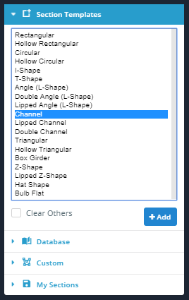
1) Stellen Sie sicher, dass die Option "Andere löschen"’ Das Kontrollkästchen ist beim Hinzufügen beider Abschnitte deaktiviert.
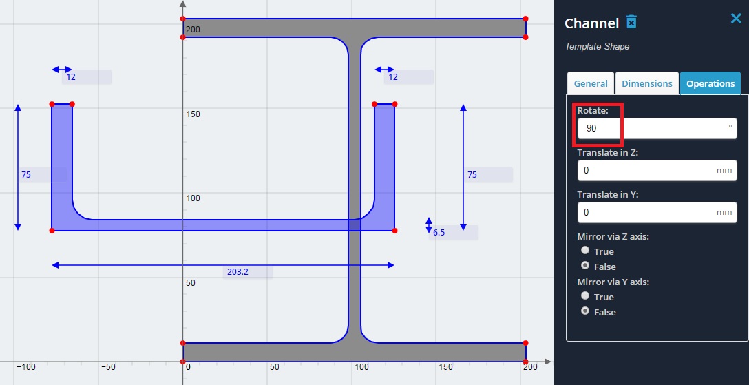
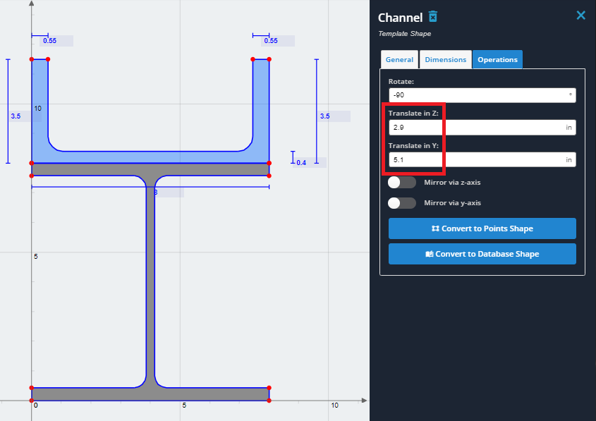
3) Drehen Sie den Kanal um -90 Grad. Klicken Sie auf „Operationen“.’ Tab und geben Sie ein -90 für den Rotationswert.
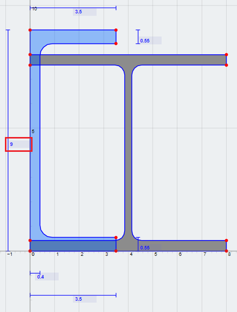
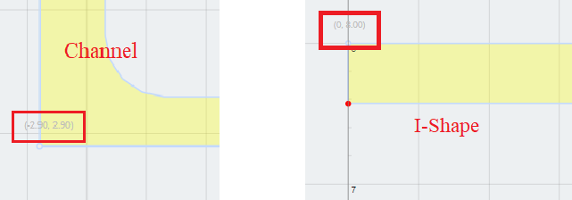
4) Stapeln Sie den Kanal oben auf dem I-Träger. Bewegen Sie dazu den Mauszeiger über die Koordinaten, wie gezeigt, und einige einfache Berechnungen durchführen. Beachten Sie, dass die Koordinaten unten links des Kanals sind (-2.90, -2.90), und die Koordinaten oben links des I-Trägers sind (0, 8.0). Um die Koordinate des Kanals an die gleiche Stelle wie die Koordinate des I-Trägers zu verschieben, Mach einfach ein Finale – Erstberechnung. Das heißt.
MIT (horizontale) Übersetzungsabstand = 0 – (-2.90) = 2.90
UND (vertikal) Übersetzungsabstand = 8.0 – 2.90 = 5.1
Dies sind die Werte zum Verschieben des Kanals in Richtung der Z- bzw. Y-Achse in den „Operationen“.’ Tab.
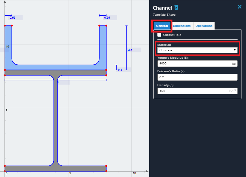
6) Wählen Sie den Kanal aus und klicken Sie auf „Allgemein“.’ Tab. Im „Material’ Dropdown-Liste, Wählen Sie „Beton“.’ aus der Liste. Nochmal, Die Materialeigenschaften können bearbeitet werden. Verwenden Sie für dieses Beispiel jedoch die Standardbetoneigenschaften.
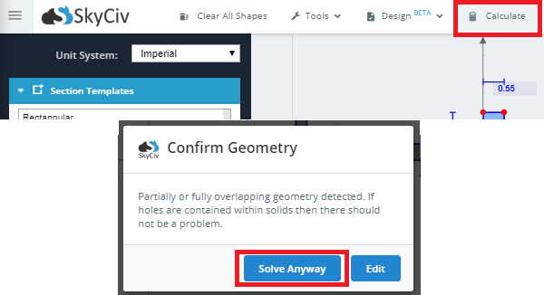
7) Sie haben nun erfolgreich einen Verbundabschnitt erstellt. Zur Berechnung der Abschnittseigenschaften, Klicken Sie auf „Berechnen“.’ Schaltfläche in der oberen Symbolleiste. Wenn Sie ein Popup-Fenster mit der Meldung überlappende Geometrie sehen, Klicken Sie auf „Trotzdem lösen“.’ da sich die Geometrien gerade berühren. Die Ergebnisse werden sowohl für den Originalabschnitt als auch für den transformierten Abschnitt angezeigt. Eine Erläuterung der Ergebnisse wird im Abschnitt „Ergebnisse“ erläutert.