In diesem Artikel, Wir zeigen Ihnen, wie Sie mit der SkyCiv-Software einen Stahlbetonträger entwerfen. Dieses Tutorial behandelt zwei von SkyCiv bereitgestellte Softwareoptionen für das Balkendesign: Der SkyCiv-Beam und Structural 3D. Wir werden uns mit beiden Tools befassen, um Ihnen den effektiven Zugriff auf und die Konstruktion von Trägern zu erleichtern. Am Ende des Artikels, Wir werden auch die in ACI-318-19 vorgeschriebene Koeffizientenmethode für die RC-Trägerkonstruktion anwenden.
Wenn Sie neu im Balkendesign sind, Wir empfehlen Ihnen, einige einführende SkyCiv-Artikel zu lesen:
- Was ist Stahlbeton?
- So berechnen Sie den Biegemomentwiderstand für einen Balkenabschnitt?
- So analysieren Sie einen kontinuierlichen Strahl?
Diese Tutorials helfen Ihnen dabei, den allgemeinen Prozess der Balkenkonstruktion besser zu verstehen.
Wenn Sie neu bei SkyCiv sind, Melden Sie sich an und testen Sie die Software selbst!
SkyCiv Beam Software
Die erste Station ist die Erstellung des Strahlmodells in der SkyCiv Beam-Software. Wir weisen darauf hin die erforderlichen Schritte: (In Klammern, Wir zeigen die Beispieldaten):
- Auf der Dashboard-Seite, Wählen Sie das Strahlmodul aus.
- Erstellen Sie einen Balken, indem Sie seine Länge definieren (66 ft).
- Gehen Sie zu Stützen und definieren Sie Scharniere oder einfache Stangen (Scharnier am Anfang und am Ende; Stange an dritten Punkten).
- Gehen Sie zu den Abschnitten und erstellen Sie einen rechteckigen (rechteckiger Abschnitt; Breite = 18 Zoll; Höhe=24 Zoll).
- Wählen Sie dann die Schaltfläche „Flächenlast“ aus und weisen Sie eine zu, zwei, oder mehr, je nach Bedarf (überlagerte Eigenlast = 0.25 kip/ft; Nutzlast = 0.40 kip/ft)
- Der nächste Schritt besteht darin, einige Lastkombinationen zu erstellen (\({L_d = 1,2times D + 1.6\mal L}\))
- Schließlich, Lösen Sie den Balken!
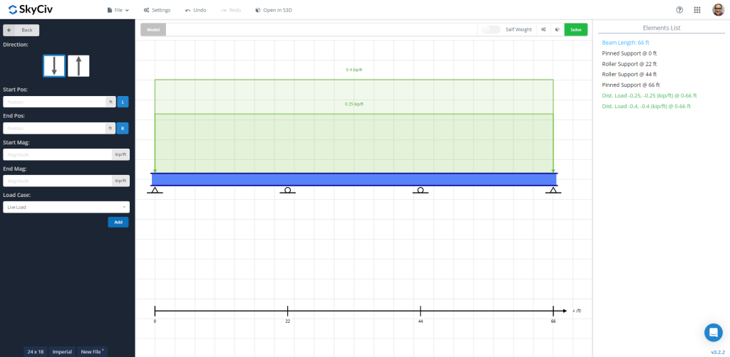
Abbildung 1: Balkenmodell mit aufgebrachten Eigen- und Nutzlasten
Nach dem Lösen des Balkens, Wir können die Ergebnisse überprüfen, wie das Biegediagramm, um ihre Maximalwerte entlang der Elementlänge zu erhalten. Die folgenden Bilder zeigen die endgültige Ausgabe.
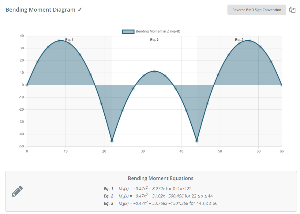
Abbildung 2: Biegemomentdiagramm aufgrund der angegebenen Lastkombination
Die SkyCiv Beam Software liefert uns eine Tabelle mit den Maximalwerten für Kräfte, betont, und Verschiebung:
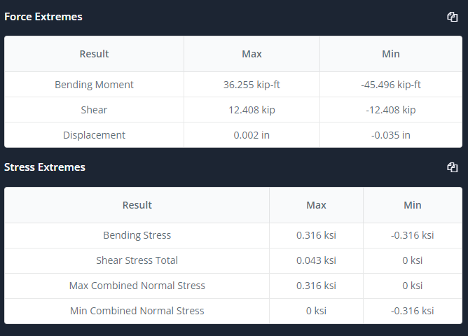
Abbildung 3: Übersichtstabelle
Jetzt ist es an der Zeit, die Registerkarte „Design“ auszuwählen und die Eingabe als Bewehrungslayout auszuwählen und zu definieren, Analyseabschnitte, einige Koeffizienten, Lastkombinationen, etc. Schauen Sie sich Zahlen an 4 und 5 für weitere Beschreibung.
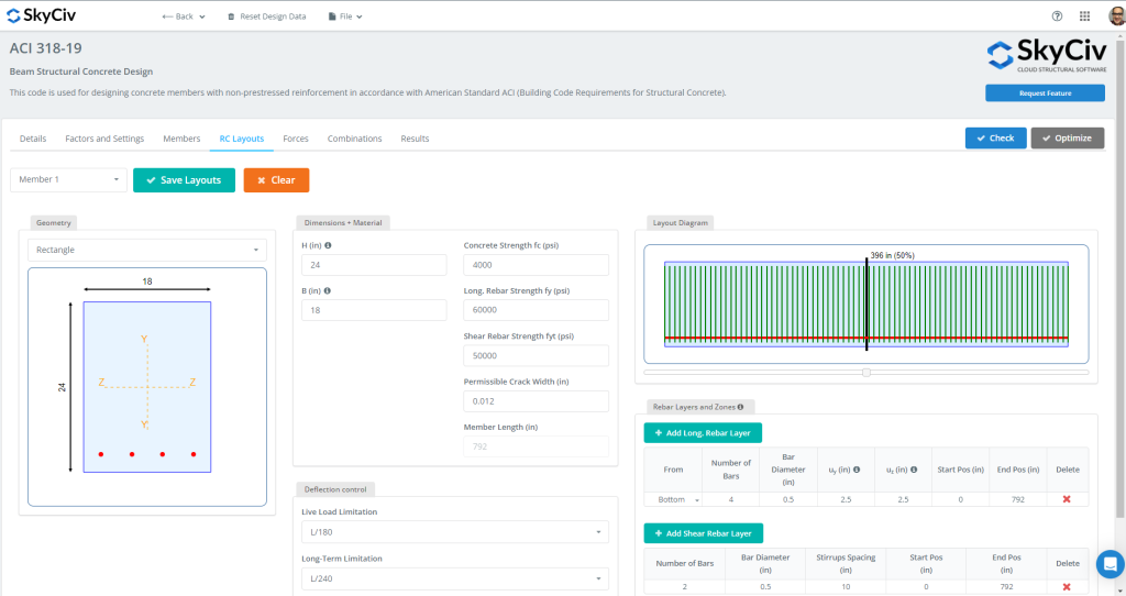
Abbildung 4: RC-Trägerlayouts
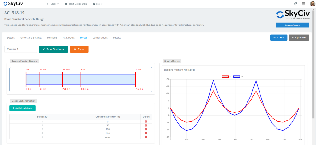
Abbildung 5: Beim Entwurf zu bewertende Kräfte und Abschnitte
Sobald alle Daten bereit sind, Wir können auf klicken “Prüfen” Taste. Diese Aktion wird uns dann die Ergebnisse und die Kapazitätsverhältnisse für Festigkeit und Gebrauchstauglichkeit liefern.
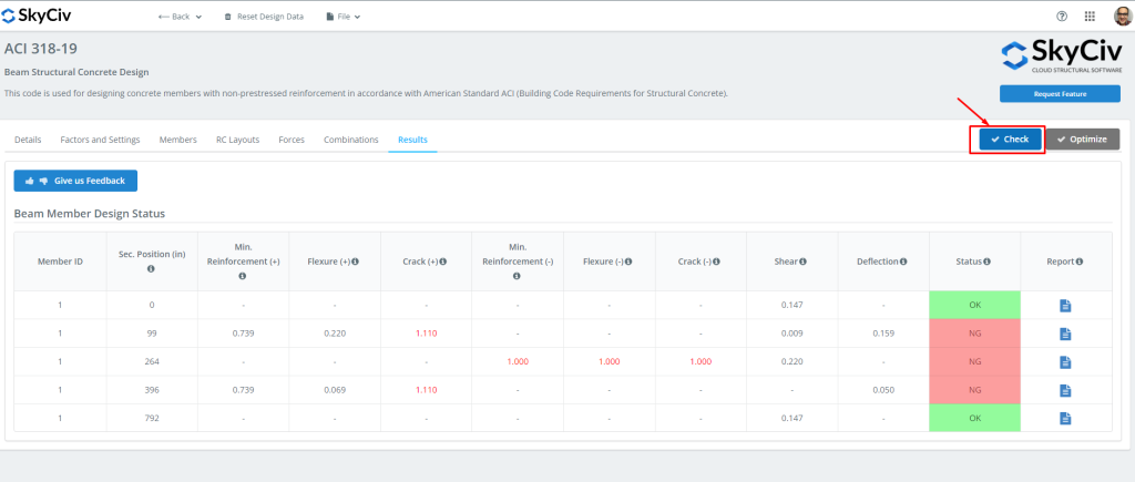
Abbildung 6: Ergebnisse des Balkenmoduldesigns.
Anschließend können Sie alle benötigten Berichte herunterladen!
Wenn Sie neu bei SkyCiv sind, Melden Sie sich an und testen Sie die Software selbst!
SkyCiv Structural 3D
Jetzt ist es an der Zeit, Structural 3D zu verwenden! Wir empfehlen, einfach zur Strahlsoftware zurückzukehren und auf zu klicken “In S3D öffnen” Taste. Dies wird uns helfen, das Modell und seine Eingaben in S3D vorzubereiten.
Sobald wir auf die Schaltfläche „Ändern“ geklickt haben, Das Modell wurde automatisch erstellt. Denken Sie daran, es zu speichern! (Wenn Sie sich mit diesem Modul vertraut machen müssen, Schau dir das an Tutorial-Link!)
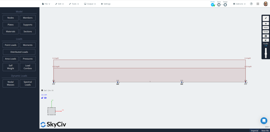
Abbildung 7: Automatisch erstelltes Modell in S3D.
Gehen Sie nun direkt zum “Lösen” Symbol zur Auswahl des “Lineare Analyse” Wählen Sie die Mitglieder aus, die Sie wiederholen möchten. Schauen Sie sich die Ergebnisse gerne an und vergleichen Sie sie; Wir werden das verwenden “Design” Wählen Sie die Mitglieder aus, die Sie wiederholen möchten. Es ist an der Zeit, auf den verschiedenen Registerkarten alle zur Bewertung des Trägers erforderlichen Eigenschaften zu definieren.
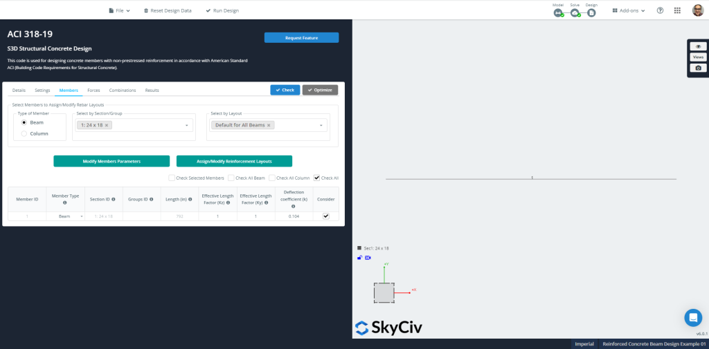
Abbildung 8: Mitglieder’ Informationen zur Gestaltung
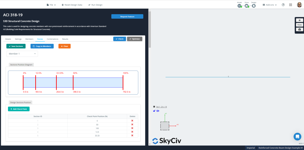
Abbildung 9: Mitglieder’ Kräfte und Abschnitte für die Bemessung
SkyCiv kann nach einem bestimmten definierten RC-Layout suchen oder eine Optimierung der Abschnittsverstärkung berechnen. Wir möchten Ihnen empfehlen, diese letztere Option auszuführen.
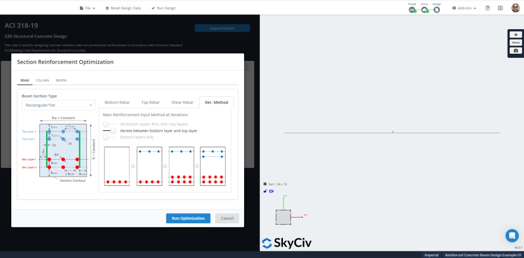
Abbildung 10: Optimierung der Abschnittsbewehrung.
Zahlen 11 und 12 Zeigen Sie das Endergebnis und die vorgeschlagene Abschnittsbewehrung an, die für den Optimierungsentwurf berechnet wurde.
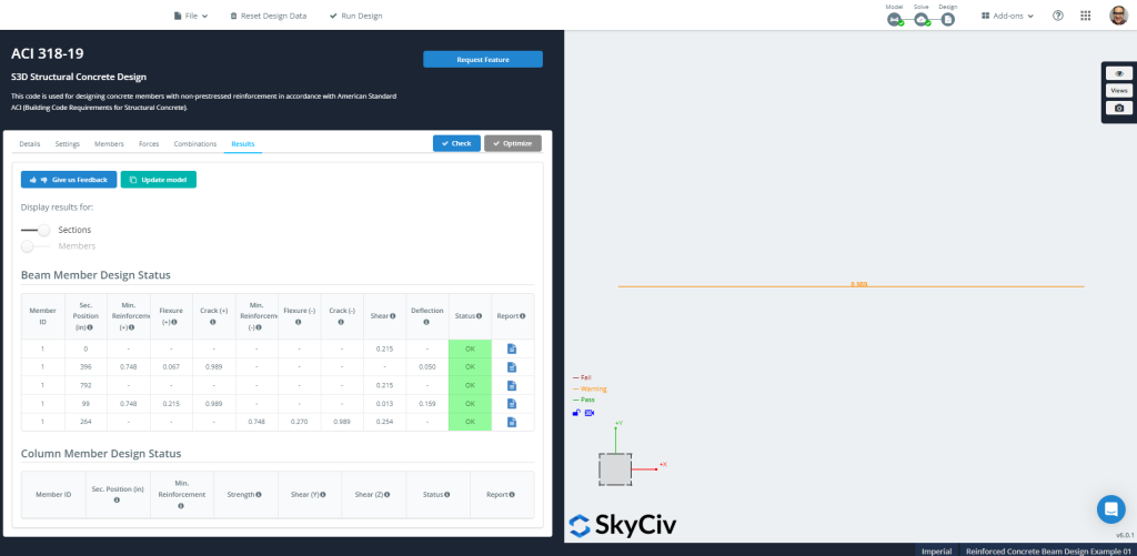
Abbildung 11: Ergebnisse der strukturellen Betonkonstruktion
Anschließend können Sie alle benötigten Berichte herunterladen!
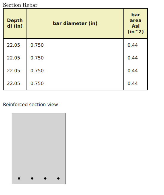
Abbildung 12: Optimierung im Profilbewehrungsstahl
Wenn Sie neu bei SkyCiv sind, Melden Sie sich an und testen Sie die Software selbst!
ACI-318 Näherungsgleichungen
Beim Entwurf eines durchgehenden Trägers, ACI-318 erlaubt die Verwendung von Momentkoeffizienten für Biegeberechnungen. (Weitere Beispiele, Schauen Sie sich gerne diese Artikel von SkyCiv an ist ein wichtiger Designstandard für die USA und viele andere Länder)
Momente an kritischen Abschnitten werden mit berechnet: \( M_u = Koeffizient times w_u times l_n^2 \). Der Koeffizient kann wie folgt ermittelt werden:
- Außenspanne:
- Negatives Äußeres: \(\frac{1}{16}\)
- Positiver Midspan: \(\frac{1}{14}\)
- Negatives Interieur:\(\frac{1}{10}\)
- Innenspanne:
- Negativ: \(\frac{1}{11}\)
- Positiver Midspan: \(\frac{1}{16}\)
Wir werden zwei Fälle auswählen: der absolute Maximalwert für positive und negative Biegemomente.
\(wu=1,2times D + 1.6\mal L = 1.2 \mal 0.25 + 1.6 \mal 0.4 = 0.94 \frac{kip}{ft} \)
\(M_{u,neg} = {\frac{1}{10}}{\mal 0.94 {\frac{kip}{ft}}}{\mal {(22 ft)}^ 2} = 45.50 {kip}{ft} \)
\(M_{u,Pos} = {\frac{1}{14}}{\mal 0.94 {\frac{kip}{ft}}}{\mal {(22 ft)}^ 2} = 32.50 {kip}{ft} \)
Berechnung des Biegewiderstands für negatives Moment, \({M_{u,neg} = 45.50 {kip}{ft}}\)
- Angenommener spannungsgesteuerter Abschnitt. \({\phi_f = 0.9}\)
- Strahlbreite, \({b=18 Zoll}\)
- Bereich der Stahlverstärkung, \({A_s = frac{M_u}{\phi_ftimes 0,9dtimes fy}= frac{45.50 kip-ft times 12 in -ft }{0.9\mal 0.9(17 im )\mal 60 KSI}=0,66 {im}^ 2}\)
- \({\rho_{Min.} = 0.003162}\). Mindestbewehrungsfläche aus Stahl, \({EIN_{s,Min.}=rho_{Min.}\mal bmal d = 0.003162 \mal 18 in Zeiten 17 in =0,968 {im}^ 2}\). Jetzt, Überprüfen Sie, ob sich der Abschnitt spannungsgesteuert verhält.
- \({a = frac{A_stimes f_y}{0.85\mal f’cmal b} = frac{0.968 {im}^2times 60 KSI}{0.85\mal 4 ksitimes 18 im }= 0.95 im}\)
- \({c = frac{ein}{\beta_1}= frac{0.95 im}{0.85} = 1.12 im }\)
- \({\varepsilon_t = (\frac{0.003}{c})\mal {(d – c)} = (\frac{0.003}{1.12 im})\mal {(17im – 1.12 im)} = 0.0425 > 0.005 }\) OK!, Es handelt sich um einen Abschnitt mit kontrollierter Spannung!.
Berechnung des Biegewiderstands für positives Moment, \({M_{u,Pos} = 32.50 {kip}{ft}}\)
- Angenommener spannungsgesteuerter Abschnitt. \({\phi_f = 0.9}\)
- Strahlbreite, \({b=18 Zoll}\)
- Bereich der Stahlverstärkung, \({A_s = frac{M_u}{\phi_ftimes 0,9dtimes fy}= frac{32.50 kip-ft times 12 in -ft }{0.9\mal 0.9(17 im )\mal 60 KSI}=0,472 {im}^ 2}\)
- \({\rho_{Min.} = 0.003162}\). Mindestbewehrungsfläche aus Stahl, \({EIN_{s,Min.}=rho_{Min.}\mal bmal d = 0.003162 \mal 18 in Zeiten 17 in =0,968 {im}^ 2}\). Jetzt, Überprüfen Sie, ob sich der Abschnitt spannungsgesteuert verhält.
- \({a = frac{A_stimes f_y}{0.85\mal f’cmal b} = frac{0.968 {im}^2times 60 KSI}{0.85\mal 4 ksitimes 18 im }= 0.95 im}\)
- \({c = frac{ein}{\beta_1}= frac{0.95 im}{0.85} = 1.12 im }\)
- \({\varepsilon_t = (\frac{0.003}{c})\mal {(d – c)} = (\frac{0.003}{1.12 im})\mal {(17im – 1.12 im)} = 0.0425 > 0.005 }\) OK!, Es handelt sich um einen Abschnitt mit kontrollierter Spannung!.
Schließlich, Wir können das für beide Momente sehen, negativ und positiv, Das Ergebnis ist die Zuordnung einer Mindestbiegebewehrung. Die benötigte Bewehrungsfläche ist gleich \(0.968 {im}^2).
Verwandte Tutorials
Wenn Sie neu bei SkyCiv sind, Melden Sie sich an und testen Sie die Software selbst!