
Was ist eine Scherverbindung??
A shear connection is a joint that transfers shear force between two members without transferring meaningful moment. If a beam carries internal Querkraft, that force passes through the connection into the supporting column as Axialkraft. Shear connections behave as a pin (FFFFFR in SkyCiv Structural 3D), unlike Moment Verbindungen, which hold the end rotation.
In AISC 360-16 terms this is a einfach Verbindung: it is assumed to rotate freely and to carry negligible moment. AS 4100:2020 calls the equivalent arrangement simple construction. A semi-rigid joint is a third case, with real but partial rotational stiffness, and it has to be modelled that way rather than treated as simple.
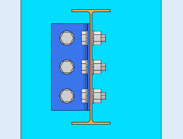
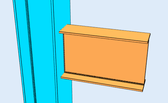
A plate or angle carries the force between the two members. Im Beispiel oben, any downward load on the beam passes into the supporting member through the angle. Because nothing restrains the beam flanges, the joint can rotate, which is what makes it a shear connection rather than a moment connection.
Schubverbindungen are the most common connection in steel framing. Where a frame is braced, the bracing provides the lateral stability, so moment connections are needed only where the frame relies on frame action. That is why most designers reach for a shear connection wherever the analysis allows: they are simpler to fabricate and cheaper to erect.
SkyCiv Connection Design checks shear connections to AISC 360-16 sowohl bei ASD als auch bei LRFD, und zu AS 4100:2020.
Arten von Scherverbindungen
Shear connections are named after the component that carries the load and where it sits. Which ones are available depends on the design code and on what the beam frames into, so the lists below are split that way.
Träger zur I-Profil-Säule, or beam to beam (AISC 360-16)
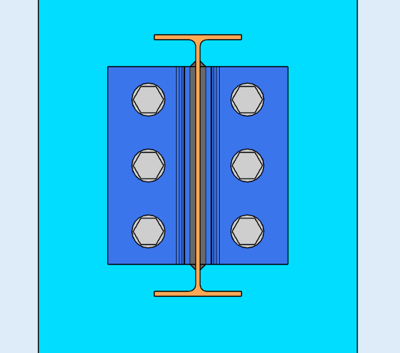
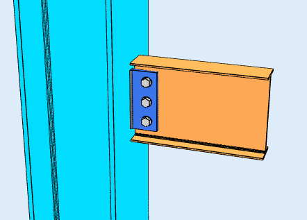
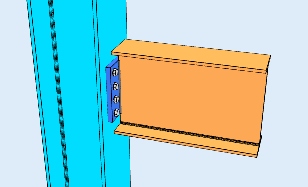
Six configurations, each available framing to the column flange, to the column web, or beam-to-beam through the web:
- Einzelwinkel. One L-shaped bracket between the beam web and the support. The lightest option, and the most flexible, so it suits light loads.
- Doppelwinkel. Angles on both faces of the beam web. The extra angle roughly doubles the bolt shear planes and makes the connection more forgiving during erection, which is why it is the workhorse for heavier beams.
- Einzelplatte. The shear tab. One plate, shop-welded to the support and bolted to the beam web. Usually the cheapest of the group, because there is one weld line and one bolt group.
- Doppelplatte. Plates on both faces of the web, used where a single plate cannot carry the shear or fit the required bolt group.
- Endplatte. A plate welded to the beam end and bolted to the support. It needs the beam cut to length accurately, since the plate leaves no adjustment.
- Direkt geschweißtes Netz. The beam web welded straight to the support, with no intermediate plate or angle. There are no bolts to check, but it needs field welding and gives up the erection tolerance a bolted detail provides.
Balken zur HSS-Säule (AISC 360-16)
Framing into a hollow section changes what fits, because there is no flange to bolt to and no access to the far side for a wrench. Five configurations are available:
- Einzelwinkel und Doppelwinkel
- Einzelplatte
- Single WT. A tee cut from a wide flange, its stem welded or bolted to the beam web and its flange to the column face.
- einen Trägersteg mit dem Tragelement zu verbinden. An angle under the bottom flange carrying the beam in bearing, normally with a top clip for stability. Unlike the web-connected types, this one works off the flange.
AS 4100:2020
The Australian code covers beam-to-I-column and beam-to-beam framing, with four configurations:
- Web-Seitenplatte, the AS 4100 name for the shear tab.
- Flexible Endplatte
- Einzelwinkel und Doppelwinkel
AS 4100 coverage is shear only, and does not extend to HSS columns, Kanäle, bracing or splices. Those are AISC 360-16.
Was prüft die Software??
For a shear connection, the design runs both a detailing pass and a strength pass.
Detailing runs first and catches the geometry: Bolzenrandabstände, Schraubenabstand (Tonhöhe und Spurweite), Werkzeugabstände, and minimum and maximum plate dimensions, plus clash detection between plates, Schrauben und Schweißnähte. A connection that fails here never reaches the solve. That is usually what you want, because the numbers do not matter if the detail cannot be built.
The strength checks then cover bolt shear, Bolzenlager und Ausreißer, Blockscherbruch, Plattennachgeben und Bruch, Schweißnahtspannung, and the local limit states of the supporting member such as web local yielding. Jede Formel, Die Designprüfung und die Codereferenz werden vollständig angezeigt, with the clause numbers from AISC 360-16 oder AS 4100:2020, So können Sie der Berechnung folgen, statt sie auf Vertrauen zu verlassen.
For the fastener side of this, siehe Dokumentation unter Schrauben und Schweißnähte.
Was ist der Unterschied zwischen einer Scher- und Momentverbindung??
A shear connection transfers shear only. A moment connection also transfers bending. Think of it as a Scharnier: a shear connection lets the beam end rotate, a moment connection holds it.
The distinction is a decision about the analysis model, not only about the detail. Eine so einfach gestaltete Scherlasche muss flexibel genug sein, dass sie sich tatsächlich drehen kann, und eine Momentenverbindung muss steif genug sein, um die vom Rahmenmodell angenommene Festigkeit zu rechtfertigen.
| Scherverbindung | Moment Verbindung | |
|---|---|---|
| Übertragene Kräfte | Nur Scherung | Scherung und Moment |
| Alternative Namen | Gepinnt, Scharnier, Einfach | Starr, Fest, Momentbeständig |
| AISC 360-16 Begriff | Einfache Verbindung | FR- oder PR-Momentanschluss |
| Drehung | Ermöglicht die Drehung | Restrains Rotation |
| Software-Fixitätscode | FFFFFR | FFFFFF |
SkyCiv Connection Design Software
Die oben genannten Modelle und Schecks stammen von SkyCiv-Verbindungsdesign. Es deckt ab 80+ vorkonfigurierte Verbindungstypen, Entwürfe an AISC 360-16 (LRFD & ASD) und 4100:2020, und zeigt jede Formel, Designprüfung und Codereferenz vollständig.
Sie können die Verbindung in 3D modellieren, Schrauben tauschen, Schweißnähte oder Bleche, ohne dass Ihre Lastdaten verloren gehen, Erstellen Sie 2D-Detailzeichnungsblätter in CloudCAD, und exportieren Sie die 3D-Geometrie zur Koordinierung in Revit nach IFC, Tekla oder Navisworks.
Es läuft vollständig im Browser, ohne Downloads, Updates oder IT-Setup.
