
Die in diesem Artikel aufgeführten Stahlverbindungen sind nach australischem Standard ausgelegt AS 4100:2020, Verbindungshandbuch des Australian Steel Institute 1, und Designleitfäden des Australian Steel Institute 1-5.
Scope of the AS 4100 Modul
Before going through the connection types, it is worth being clear about what the module covers under AS 4100.
AS 4100:2020 design in SkyCiv is for shear connections between I-sections, in metric units. Momentverbindungen, splices and bracing connections are outside the current AS 4100 scope.
Universalträger zu Universalsäule
Beam to column connections are among the most common connection types in steel design. The AS connections in SkyCiv are built around a supported beam framing into a supporting member, and the orientation can be set to a column flange support, a column web support, or a beam web support.
That third orientation means the same four connection types can also be used beam to beam, not only beam to column.
Only one connection to a node can be designed at a time. Beim Umgang mit Back-to-Back-Verbindungen, Es ist ratsam, konservative Annahmen zum Lastpfad zu treffen.
Scherverbindungen
A shear connection is a simple connection. It is detailed to carry the beam end reaction and to rotate at the joint rather than to carry end moment, which is what separates it from a moment connection. In the AS module it is designed for shear alone, with no concurrent axial load.
Für das AS-Design, the following shear connection types are available:
Each of the four is available beam to column flange, beam to column web, and beam to beam web.
-

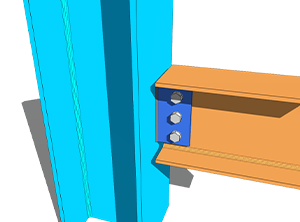
- Web-Seitenplatte – Träger zu Stützenflansch
-
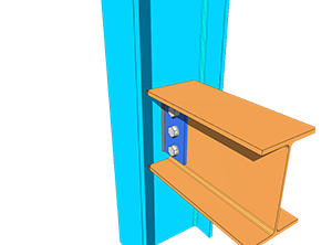
- Web-Seitenplatte – Beam-to-Column-Web
-
- Flexible Endplatte – Träger zu Stützenflansch

-
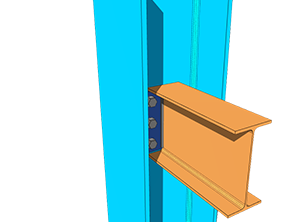
- Flexible Endplatte – Beam-to-Column-Web
-
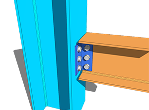
- Einzelwinkel – Träger zu Stützenflansch
-
- Einzelwinkel – Beam-to-Column-Web
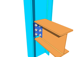
-
- Doppelwinkel – Träger zu Stützenflansch
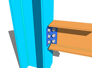
-
- Doppelwinkel – Beam-to-Column-Web
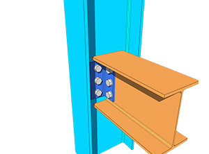
The design of the above shear connections was based mainly on ASI Design Guides 3, 4 und 5. The reference formulas were taken from the AS 4100:2020 Handbuch, while the rest of the calculations and criteria were taken from the ASI Connection Handbook 1.
Schraubengruppenkoeffizient
Für Flexibilität bei der Schraubenanordnung und dem Schraubenabstand, SkyCiv hat die ICOR-Methode und die inelastische Analyse zur Bestimmung des Schraubengruppenkoeffizienten C angepasst, which is then used to calculate the bolt group shear capacity and bolt bearing capacity.
The Instantaneous Centre of Rotation Method (ICOR) verwendet Iteration, um den IC der Schraubengruppe zu lokalisieren. SkyCiv verwendet für diese Iterationen einen eigenen Solver. Der Standort des IC geht in die Berechnungen ein, but the iterations are not shown, to keep the report concise and readable.
The equation used to calculate the force per bolt using the inelastic analysis is based on AISC Eq. (7-1) Auf Seite 7-7 des AISC-Handbuchs, 15. Ausgabe. Die Gleichung ist unten gezeigt.
[math] R = R_{ult}\left(1-e^{-10\Delta}\right)^{0.55} [math]
This is a method borrowed for the bolt group solver, not a change of design code. The capacities themselves are still checked to AS 4100:2020.
Da die Schraubengruppenkapazität die AISC-Methode angepasst hat, the provisions for determining the design bolt eccentricity of the bolt group also follow Table 10-9 der AISC 15. Ausgabe. This applies to SkyCiv’s AS Web Side Plate connection.
Eccentricity is handled differently for each type. Für Einfachwinkelverbindungen, both the NSL and OSL legs are designed with load eccentricity. Für Doppelwinkelverbindungen, only the NSL leg is designed with eccentricity, since the OSL leg is symmetrically balanced about the line of force. For Flexible End Plate connections there is no eccentricity either, as the load acts directly on the centre of the bolt group. Every bolt group without eccentricity takes the bolt coefficient C as the total number of bolts in the group.
Fixture-Typen
Each interface can be set as a bolted or a welded fixture, at the beam and at the support.
For the bolted case, siehe Dokumentation unter Schrauben; for the welded case, sehen Schweißnähte.
Einschränkungen bei der Detaillierung
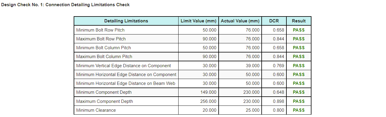
Detailing limitations, the fit-up checks on the connections, are included in the AS connection design. Most of them are based on ASI Design Guides 3-5, while some follow an intuitive engineering approach.
These checks catch the connection that satisfies every strength calculation and still cannot be built or erected, which is a failure mode that strength checks alone will not find.
A pass or fail result for the detailing limitations appears on the Results tab, so it can be identified quickly. Der Berechnungsbericht erzeugt auch eine Tabelle, unten gezeigt, so the item that needs to be modified is easy to pick out.
Weitere Verbindungsarten
Should you wish to see more connection types added under AS 4100, Sie können Kontakt aufnehmen SkyCiv-Unterstützung.
Try it now
Pick a web side plate, flexible Endplatte, single angle or double angle, enter your beam, support and loads, and the module returns every check with its utilization ratio and the reference behind it, along with the detailing limitation table. Es läuft im Browser, ohne dass es etwas zu installieren gibt, and you can do it without an account.
You can also reach it through the Kostenloser Berechnungsrechner für Stahlverbindungen.
Melden Sie sich für ein kostenloses Konto an
Mit einem kostenlosen Konto können Sie Ihre Verbindungsdateien speichern und erneut laden, which the free tool does not. It also gives you access to the rest of SkyCiv’s Struktursoftware, einschließlich strukturelles 3D.
Verbindungsdesign Standalone
Sie möchten nur das Verbindungsdesign-Modul verwenden? Klicken Sie auf die Schaltfläche unten, um die Einzelpreise anzuzeigen.
