Übersicht
Die Biegespannung ist einer der wichtigsten Werte im Strukturdesign, Wie bei den meisten horizontalen Trägern ist dies typischerweise ein kritischer oder maßgebender Entwurf. B. ein horizontaler Balken, belastet wird, es erzeugt Biegemoment Spannungen in den oberen und unteren Fasern des Abschnitts, die den Abschnitt überbeanspruchen und dazu führen können, dass er nachgibt oder vollständig versagt.
Bei der Berechnung der Biegespannung, Es ist wichtig, Folgendes zu bedenken:
- Trägheitsmoment Ihres Abschnitts – wirkt sich direkt auf die Biegespannung aus
- Wo auf dem Balken überprüfen Sie – Die Biegespannung nimmt typischerweise zu, je weiter man sich von der neutralen Achse des Abschnitts entfernt (Daher sind die Spannungen oben und unten im Abschnitt am größten)
- Die Materialeigenschaften – stärkere Materialien (höhere Streckgrenze zum Beispiel) halten höheren Belastungen stand und sind für bestimmte Konstruktionen möglicherweise besser geeignet
- Querschnittsformen – wie mit Punkt (1) über – Verschiedene Abschnitte sind gut geeignet, höheren Biegebeanspruchungen standzuhalten, aufgrund ihrer höheren Trägheitsmomentwerte
- Richtung der Spannung – Abhängig von der Richtung der Belastung kann eine Biegung sowohl in der Haupt- als auch in der Nebenachse eines Abschnitts auftreten.
- Häufig, Diese Biegespannungen können mit Scher- oder Axialspannungen kombiniert werden (aufgrund von Kräften in andere Richtungen), Erhöhung der Gesamtspannung in einem Balken
In der folgenden Anleitung gehen wir hauptsächlich darauf ein, wie man die Biegespannung berechnet (insbesondere in einem I-Träger), Beim Erlernen dieser Prinzipien ist es jedoch wichtig, den oben genannten Kontext im Auge zu behalten.
Berechnung der Biegespannung in Trägern?
Das Verständnis der Biegespannung ist wichtig, da die Balkenbiegung eine entscheidende Rolle bei der Balkenkonstruktion spielt. In diesem Tutorial erfahren Sie, wie Sie die Biegespannung in einem Balken mithilfe einer Formel berechnen. Diese Formel bezieht die Längsspannungsverteilung in einem Balken auf die innere Biegemoment wirkt auf den Querschnitt des Trägers. Wir gehen davon aus, dass das Material des Trägers ist linear-elastisch (d.h.. Hookes Gesetz anwendbar).
1. Berechnen Sie die Biegespannung manuell mit Biegespannungsformeln (Gleichungen)
Schauen wir uns ein Beispiel an. Betrachten Sie den unten gezeigten I-Strahl:
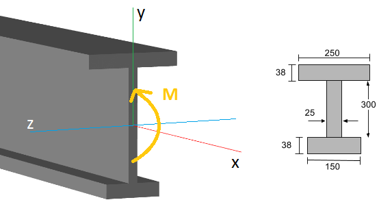
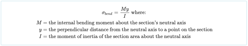
An einem bestimmten Punkt entlang der Balkenlänge (die x-Achse), Es existiert ein inneres Biegemoment (M.), normalerweise anhand eines Biegemomentdiagramms ermittelt. Die allgemeine Biegespannungsformel (oder normaler Stress) auf dem Abschnitt ist:
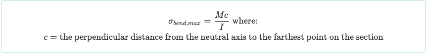
Wenn ein bestimmter Abschnitt eines Trägers betrachtet wird, Es wird deutlich, dass die Biegespannung in einem bestimmten Abstand von der Neutralachse ihren Maximalwert erreicht (j). So, Die maximale Biegespannung tritt entweder an der Ober- oder Unterseite des Trägerabschnitts auf, je nachdem welcher Abstand größer ist:
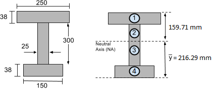
Betrachten wir das reale Beispiel unseres oben gezeigten I-Trägers. In unserem vorherigen Tutorial zum Trägheitsmoment, Wir haben bereits festgestellt, dass das Trägheitsmoment um die neutrale Achse I = 4,74 ist×108 mm4. zusätzlich, in dem Schwerpunkt Tutorial, Wir fanden den Schwerpunkt und damit den Ort der neutralen Achse 216.29 mm von der Unterseite des Querschnitts gefunden. Dies ist unten gezeigt:
Normalerweise ist es notwendig, die maximale Biegespannung zu bestimmen, der ein Abschnitt ausgesetzt ist. Zum Beispiel, Nehmen wir an, wir haben es bestimmt, aus dem Biegemomentdiagramm, dass der Balken ein maximales Biegemoment von erreicht 50 kN-m oder 50,000 Nm (nach Umrechnung der Biegemomenteinheiten).
Dann müssen wir herausfinden, ob die Ober- oder Unterseite des Abschnitts weiter von der neutralen Achse entfernt ist. Deutlich, der untere Teil des Abschnitts hat einen größeren Abstand, Messung von c = 216.29 mm. Mit diesen Informationen, Wir können mit der Berechnung der maximalen Spannung fortfahren, indem wir die oben angegebene Biegespannungsformel verwenden:
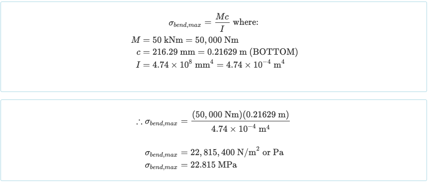
Ähnlich, Wir konnten die Biegespannung oben im Abschnitt finden, wie wir wissen, dass es y = ist 159.71 mm von der neutralen Achse entfernt (N / A):

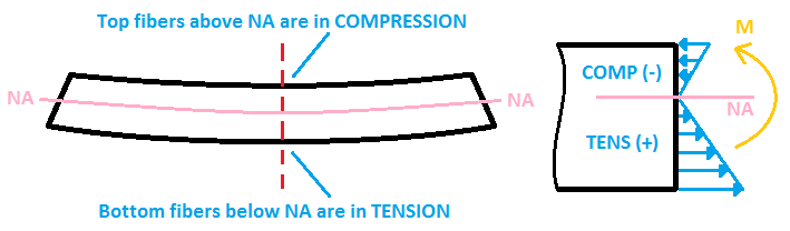
Die abschließende Überlegung umfasst die Feststellung, ob die Balkenspannung eine Kompression oder Spannung der Fasern des Abschnitts verursacht.
- Wenn der Balken durchhängt wie ein “U.” Form, Die oberen Fasern erfahren eine Kompression (negativer Stress), während die unteren Fasern einer Spannung ausgesetzt sind (positiver Stress).
- Wenn der Balken umgedreht durchhängt “U.” Form, die Situation ist umgekehrt: Die unteren Fasern werden einer Kompression ausgesetzt, während die oberen Fasern Spannung erfahren.
2. Berechnen Sie die Biegespannung mithilfe von Software
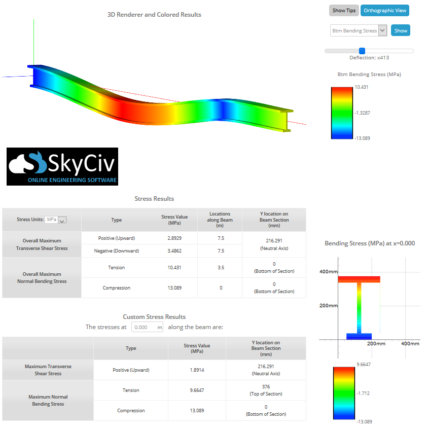
Im obigen Abschnitt wurde die Biegespannungsformel für die manuelle Berechnung besprochen, aber Sie müssen es nicht mehr manuell selbst tun SkyCiv Beam Calculator kann Ihnen dabei helfen, die Scher- und Biegespannung in einem Balken mit einem einzigen Klick zu ermitteln. Durch einfaches Modellieren des Strahls, Stützen einzubauen, und Aufbringen von Lasten, Mit diesem Biegespannungsrechner können Sie die maximalen Spannungen ermitteln. Das Bild unten zeigt ein Beispiel eines I-Trägers, der einer Biegespannung ausgesetzt ist:
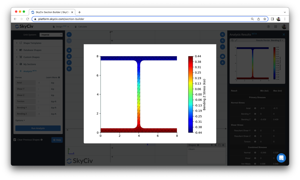
Benutzer können auch Folgendes verwenden Beam-Stress-Software um die Biegespannung und andere Balkenspannungen zu berechnen, mit einem einfachen Tool zum Erstellen von Abschnitten. Schauen Sie sich also unser Beam-Tool oben an oder melden Sie sich noch heute an, um die Software kostenlos zu testen!
Für weitere Balkendokumentationen, Besuchen Sie unsere Artikel auf Berechnung der Biegespannung eines Balkenabschnitts, wie man das Biegemoment ermittelt, Bestimmen Sie die Reaktionen am Support, und Strahlablenkung.