
A flange plate moment connection carries bending across a beam to column joint by turning the beam’s moment into a force couple: tension in one flange plate, Kompression im anderen. A separate web plate carries the shear. That division is what makes the connection straightforward to design and to build, because each component has one job.
The usual arrangement is a plate bolted to the beam flange and welded to the column. Where the frame is shop-assembled, the whole connection can be welded instead. The web plate is normally bolted at the beam web and welded to the column.
SkyCiv Connection Design checks the whole assembly to AISC 360-16 in ASD oder LRFD. You enter the beam and column sections, the plate dimensions, the bolts and welds, and the loads; it returns every check with its utilization ratio and the clause behind it.
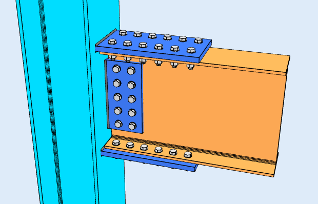
Ansicht
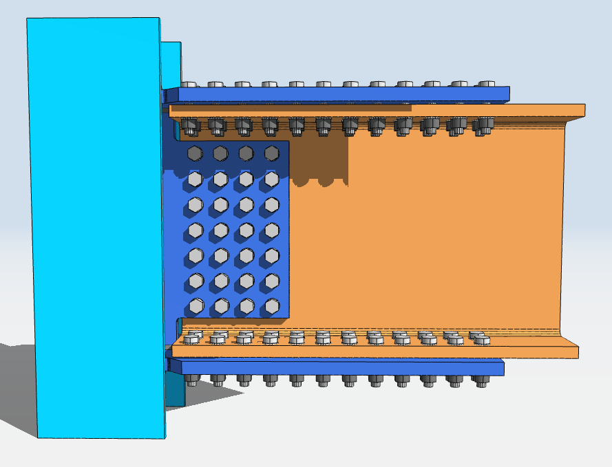
Draufsicht
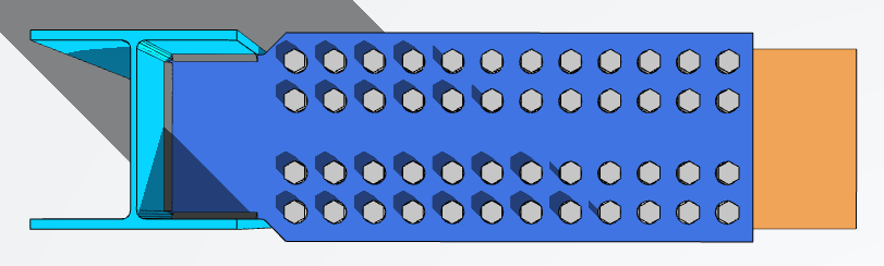
Designing a Flange Plate Connection in SkyCiv
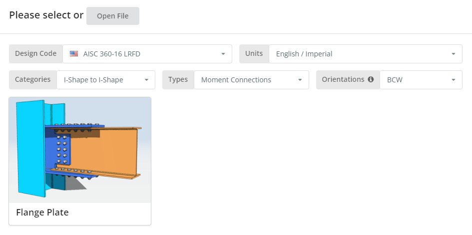
The design code can be AISC 360-16 ASD oder LRFD, and units English/Imperial or SI/Metric. Orientation is BCF or BCW; hover the tooltip for what each means. Drücke den “Flanschplatte” Fliese.
Registerkarte Details
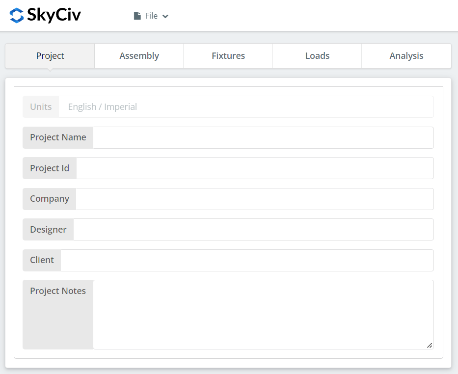
Record the project details here. None of it changes the calculations, but it carries into the report.
Registerkarte „Montage“.
Three tabs sit under Assembly: the Column, the Beam, and the Connection, which holds both the flange plate and the web plate.
Spaltenregisterkarte
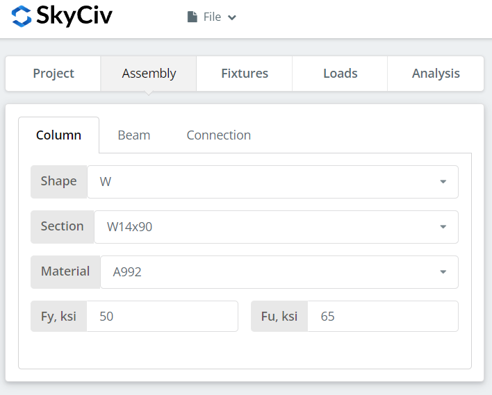
Specify the section and material grade of the column. A992 and A36 are in the list; for anything else choose Custom and enter Fy and Fu.
Balken-Registerkarte
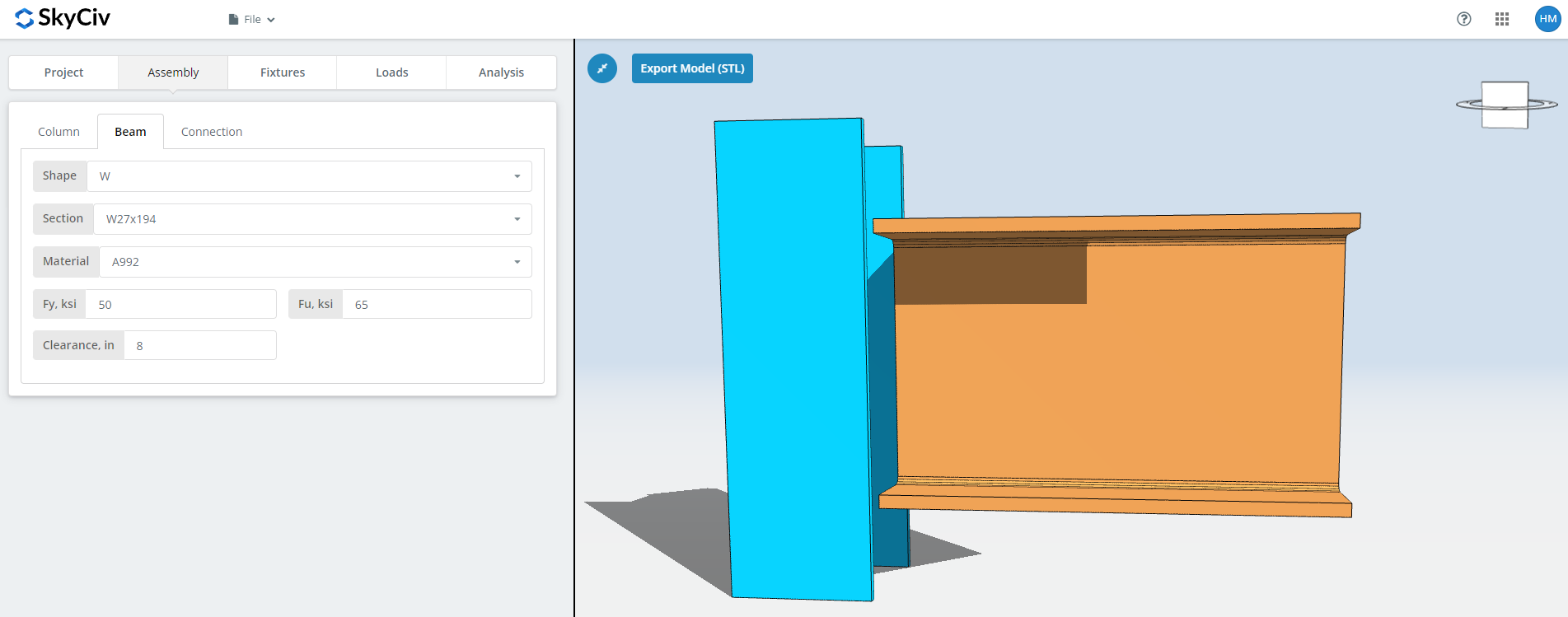
The same inputs for the beam, plus the beam clearance.
Registerkarte „Verbindung“.: Flanschplatte
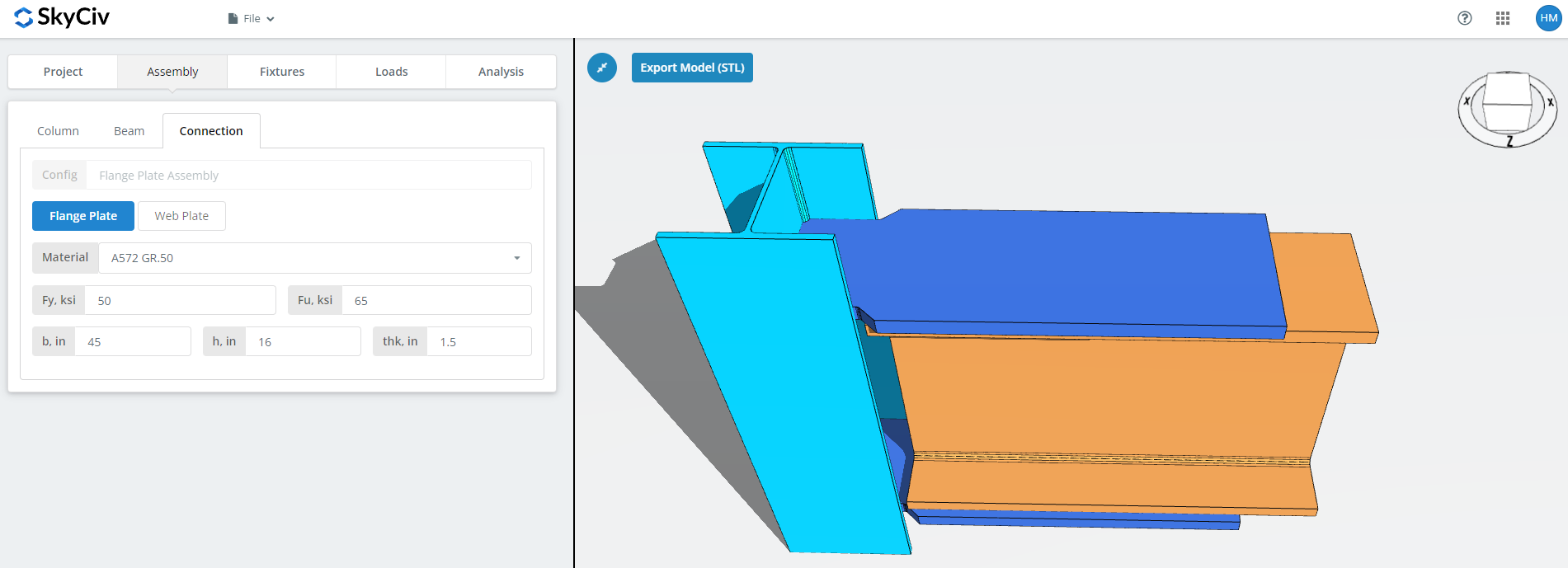
Set the flange plate properties: grade A36, A992 or A572 Gr.50, or Custom with your own Fy and Fu, then b (Breite), h (Höhe) und denke (Dicke).
This is the plate that carries the moment, so its area and the bolt group in it are what the moment capacity comes down to. Watch the 3D renderer as you type and check there is room for the bolts or welds you will define on the Fixtures tab.
Registerkarte „Verbindung“.: Stegplatte
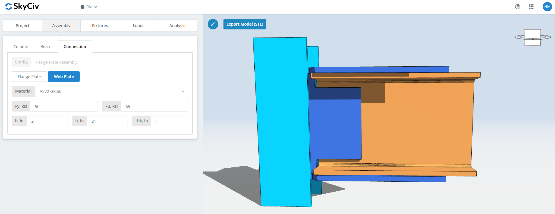
The same fields for the web plate. This one carries the shear, so its depth and bolt group are sized against the vertical load rather than the moment. Check the renderer again before moving on.
Befestigung 1 Tab
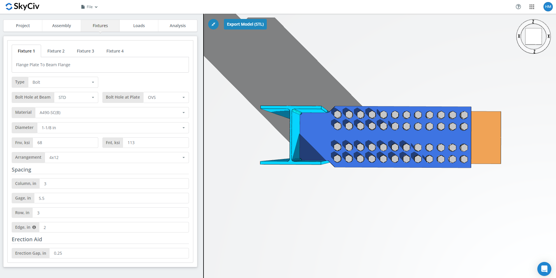
Befestigung 1 is the flange plate to beam flange connection. It can be bolted or welded; this walkthrough uses bolted.
Zuerst, the bolt hole types at the beam flange and at the flange plate. Fabricators usually ask for standard holes (STD) in the member and oversized holes (OVS) in the flange plate, which buys fitting tolerance in the field.
Als nächstes, the bolt material or grade: A307, A325, A490 or Custom. A325 and A490 are grades within ASTM F3125, which consolidated the older standalone specifications. Choose N or X for a bearing-type connection and SC for slip-critical.
Slip-critical joints have lower design bolt capacity than bearing-type, so use them where slip actually matters: oversized or slotted holes, load reversal, or fatigue. In diesem Beispiel, using OVS holes in either the beam or the plate means the bolts are automatically checked as slip-critical. Between N and X, X gives the larger bolt shear capacity, but the threads must be excluded from the shear plane, and the erector has to know that. Between SC(Ein) and SC(B.), SC(B.) gives the larger capacity and requires a more thoroughly prepared faying surface, for example SSPC-SP6 commercial blast cleaning.
Then the bolt diameter, from 5/8″ to 1-1/2″ or the metric equivalents, and the arrangement, bis zu 8 Bolzenreihen und 12 Bolzensäulen, with the row spacing, column spacing and gage. Mit der “Kante” input is the distance from the beam end to the first bolt column.
Zuletzt, the erection gap. This is the gap that lets the beam be dropped into place on site. It costs capacity, so specify it only where erection actually needs it, and say so on the drawing when you do.
Befestigung 2 Tab
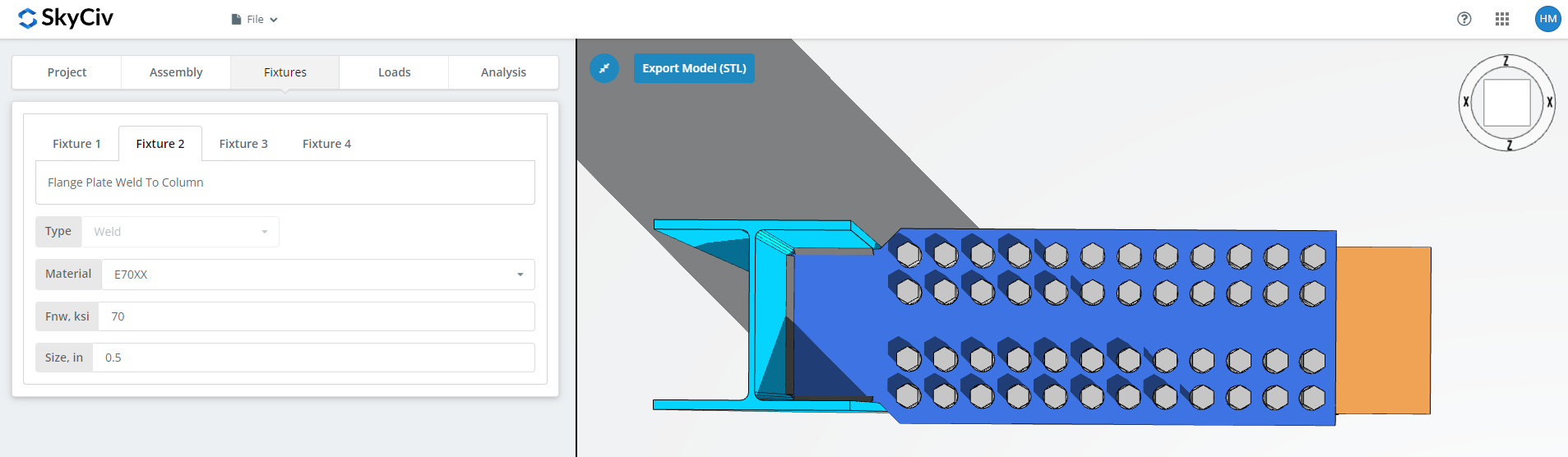
Befestigung 2 is the flange plate to column connection, to the column web and flange for BCW or to the column flange for BCF. This one is welded only.
Specify the weld material, or choose ‘Custom’ and enter Fnw if the electrode you want is not listed, then the weld size.
Befestigung 3 Tab
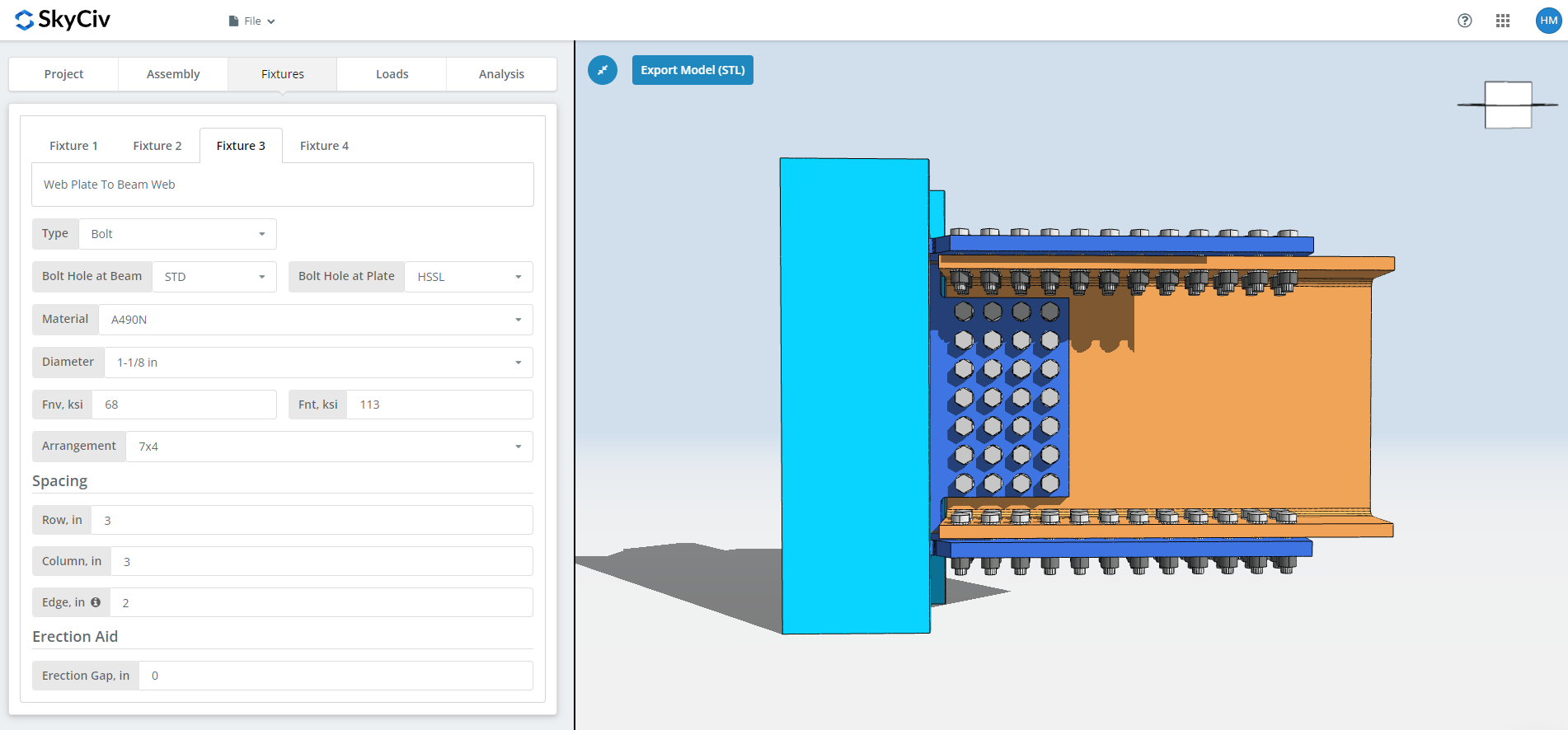
Befestigung 3 is the web plate to beam web connection. It can be bolted or welded; this walkthrough uses bolted.
Zuerst, the bolt hole types at the beam web and at the web plate. Fabricators usually ask for standard holes (STD) in the member and horizontal short-slotted holes (HSSL) in the web plate.
Als nächstes, the bolt material or grade: A307, A325, A490 or Custom, with the same N, X and SC choices as Fixture 1. The slip-critical and thread-exclusion notes above apply here too.
Then the bolt diameter, from 5/8″ to 1-1/2″ or the metric equivalents, and the arrangement, bis zu 12 Bolzenreihen und 12 Bolzensäulen, with the row and column spacing. Mit der “Kante” input is the distance from the beam end to the first bolt column.
Zuletzt, the erection gap, as above.
Befestigung 4 Tab
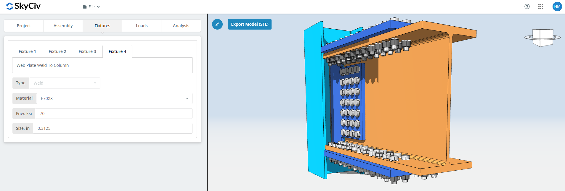
Befestigung 4 is the web plate to column web or flange connection, and like Fixture 2 it is welded only. Specify the weld material, or ‘Custom’ with your own Fnw, and the weld size.
For more on the fastener side, see the documentation on Schrauben und Schweißnähte.
Registerkarte Lasten
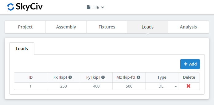
Enter the horizontal axial load under ‘Fx’, the vertical shear under ‘Fy’, and the strong axis moment under ‘Mz’.
Match the loads to the design method you picked at the start. LRFD takes factored loads against design strength; ASD takes service loads against allowable strength. The software cannot tell which you typed.
Registerkarte Ergebnisse
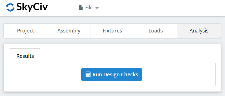
Klicken “Führen Sie Designprüfungen durch”. Anything missing from the earlier tabs is flagged here rather than silently defaulted.
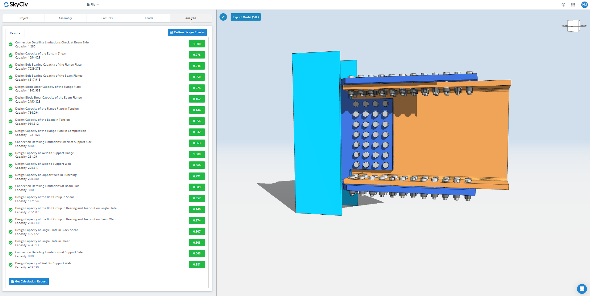
The summary shows whether the connection passed, with a utilization ratio against each check. Wenn es fehlgeschlagen ist, change the inputs on the earlier tabs and click “Designprüfungen erneut ausführen”. When it passes, “View Calculation Report” opens the detailed report.
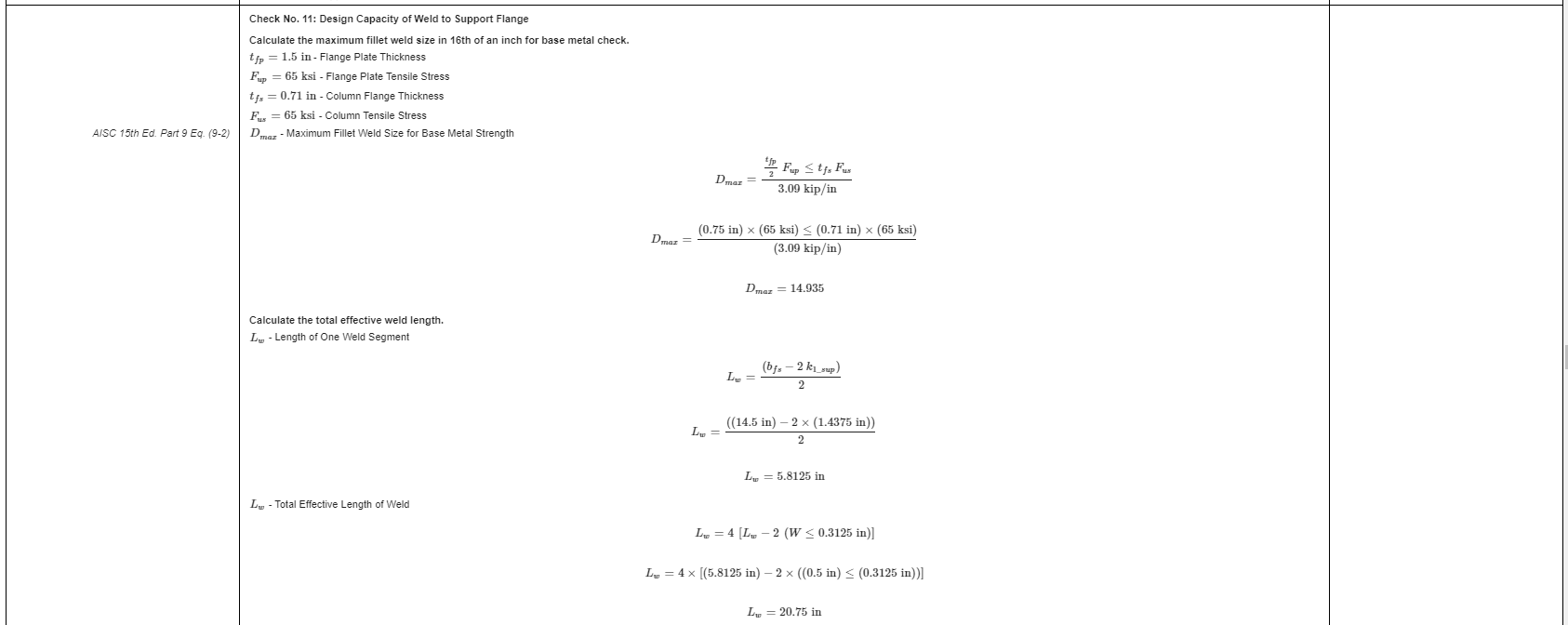
That is an extract from the report. Each check carries its reference to the AISC manual or specification, and the working follows the order the specification uses, so a reviewing engineer can read it line by line instead of reverse-engineering a number.
Hier ist eine PDF-Kopie des vollständigen detaillierten Berechnungsberichts: Verbindungsentwurfsbericht.
Try It Yourself
Pick the flange plate connection, Geben Sie Ihre Abschnitte ein, Platten, bolts and loads, and see every check with its code reference. Es läuft im Browser, ohne dass es etwas zu installieren gibt.
See also the Rechner für Flanschplattenverbindungen, bleibt die Momentverbindungsrechner und das Moment Verbindungen overview.
