
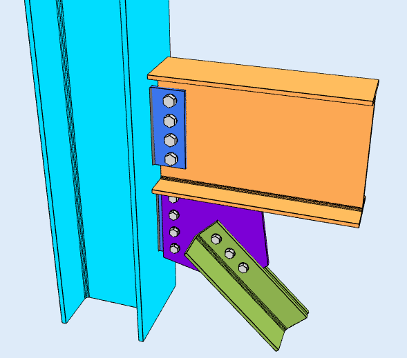
A vertical brace carries lateral load down through a braced bay as axial force, rather than by bending the frame. At each end the brace force has to be resolved into the beam and the column, and that is the job of the gusset plate. The connection is therefore three interfaces working together: brace to gusset, gusset to beam, and gusset to column.
SkyCiv Connection Design checks the vertical brace connection to AISC 360-16 in ASD oder LRFD. It resolves the gusset interface forces by the Uniform Force Method, then returns every check with its utilization ratio and the clause behind it.
Braced Frames Against Moment Frames
A braced frame resists lateral load axially. The members work in tension and compression, so they stay light, and the connections are mostly bolted shear and bearing work that a fabricator can produce without special procedures. A moment frame resists the same load in flexure, which needs heavier members and connections stiff enough to transfer moment, often with complete joint penetration welds at the flanges. For the same drift limit, the braced frame is usually the cheaper structure.
What the braced frame costs is the bay itself. A diagonal running corner to corner blocks that bay for doors, glazing and services, and the architect has to plan around it. A moment frame leaves the bay clear, which is why it survives in frontages and open floor plates despite costing more. Bracing saves steel; it constrains the layout rather than freeing it.
Where a full diagonal will not fit, the usual answers are a chevron brace, which frees the centre of the bay for an opening, oder ein Kniestütze, which sits in the corner.
The module designs these connections to AISC 360-16. Seismic force-resisting detailing, the ductility and capacity-design rules in AISC 341, is not covered. If the brace is part of a seismic force-resisting system, the demands you enter have to come from that assessment.
Designing a Vertical Brace Connection in SkyCiv
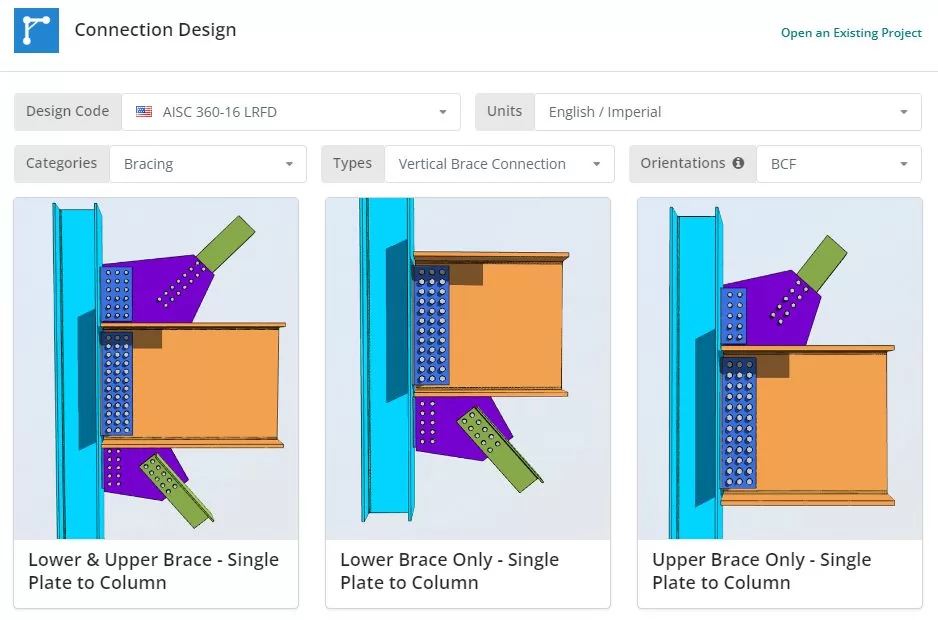
Der Designcode kann AISC sein 360-16 ASD oder LRFD, und Einheiten Englisch/Imperial oder SI/Metrisch. Die Abstützung ist nur unter AISC verfügbar; it is not offered under AS 4100.
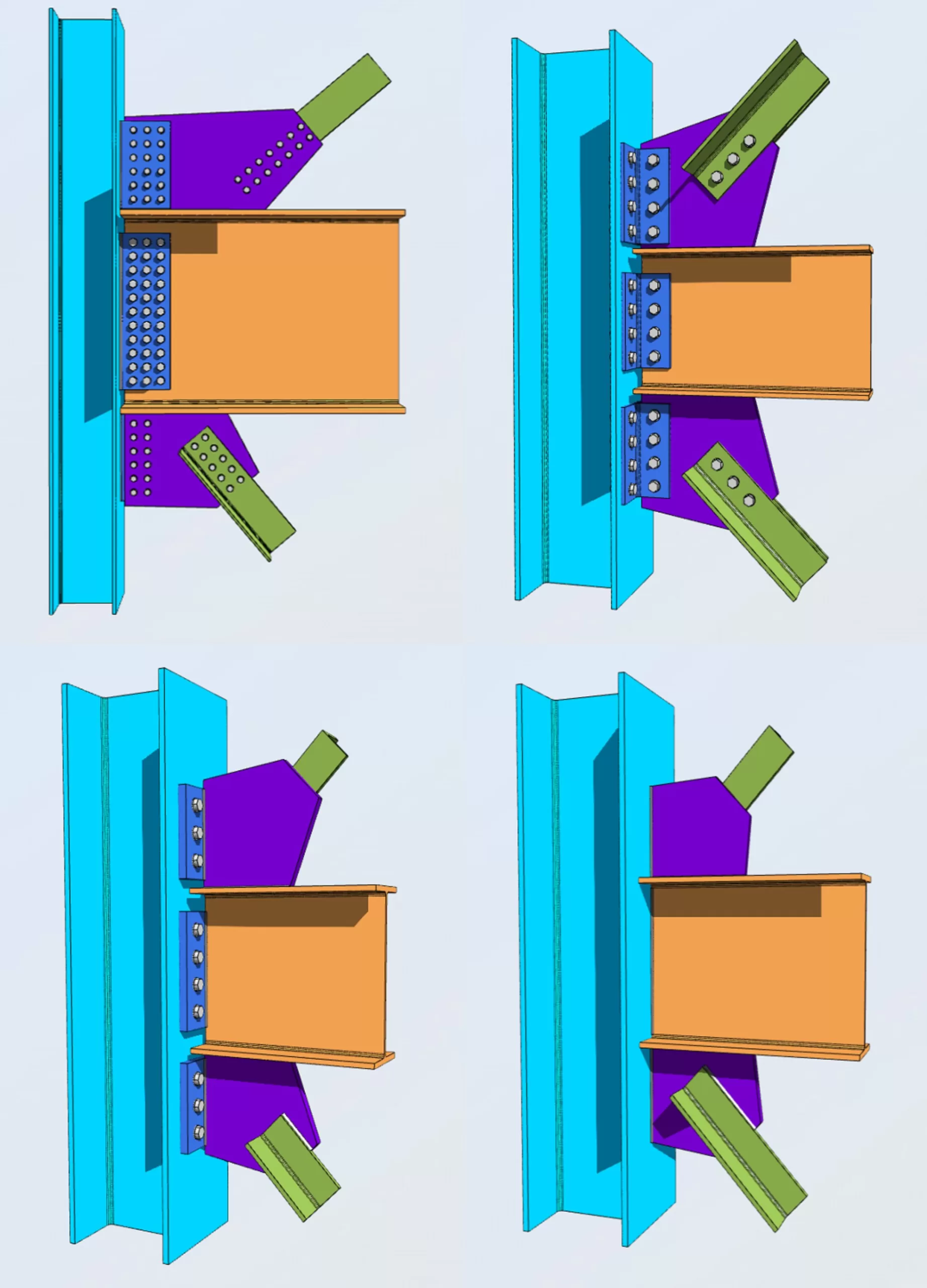
Click any tile to start. There are four connections to the column, Einzelplatte, Doppelwinkel, Endplatte and directly welded, and each comes in a lower brace only, upper brace only, or lower and upper variant. The choice sets both the beam to column connection and the gusset to column connection. Each configuration can frame to the column flange or the column web.
Registerkarte Details
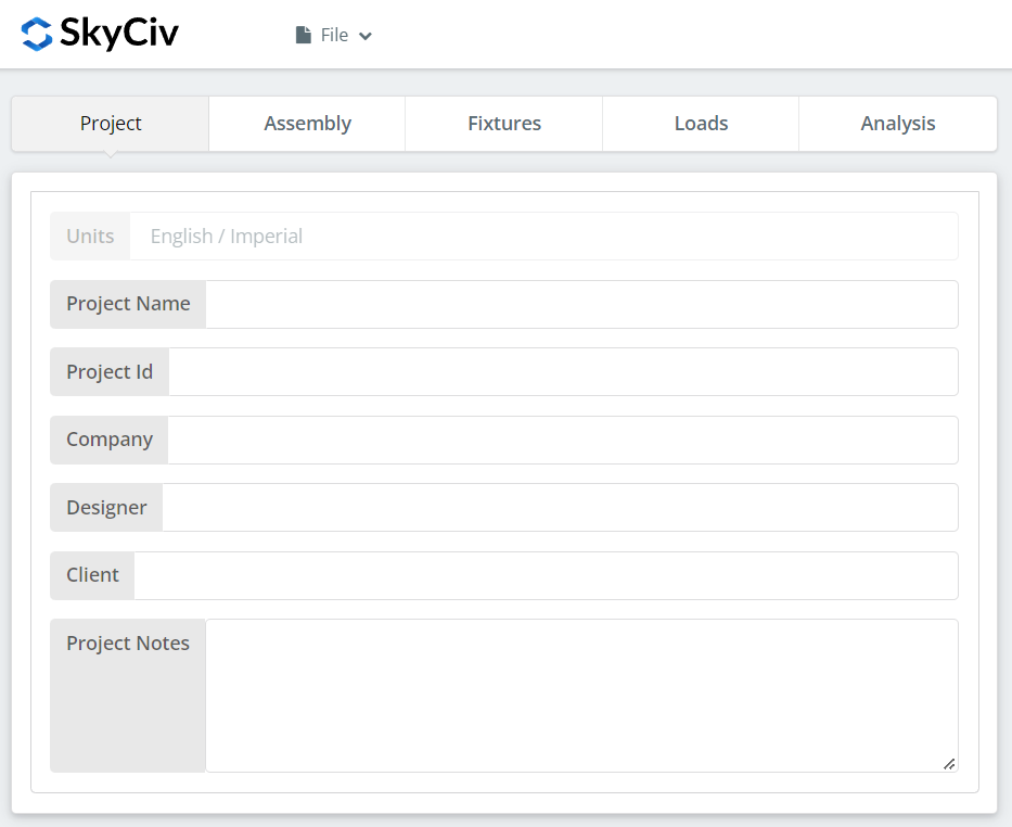
Tragen Sie hier die Projektdetails ein. Nichts davon ändert die Berechnungen, aber es geht in den Bericht über.
Registerkarte „Montage“.
The tabs under Assembly are the Column, der Balken, the Brace or Braces, und die Verbindung, which holds the gusset plate and any angle. A configuration with both an upper and a lower brace has a tab for each, so the count is four or five depending on the tile you picked.
Spaltenregisterkarte
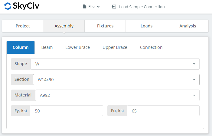
Balken-Registerkarte
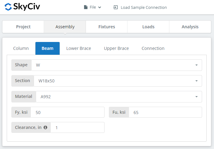
Registerkarte „Untere oder obere Stütze“.
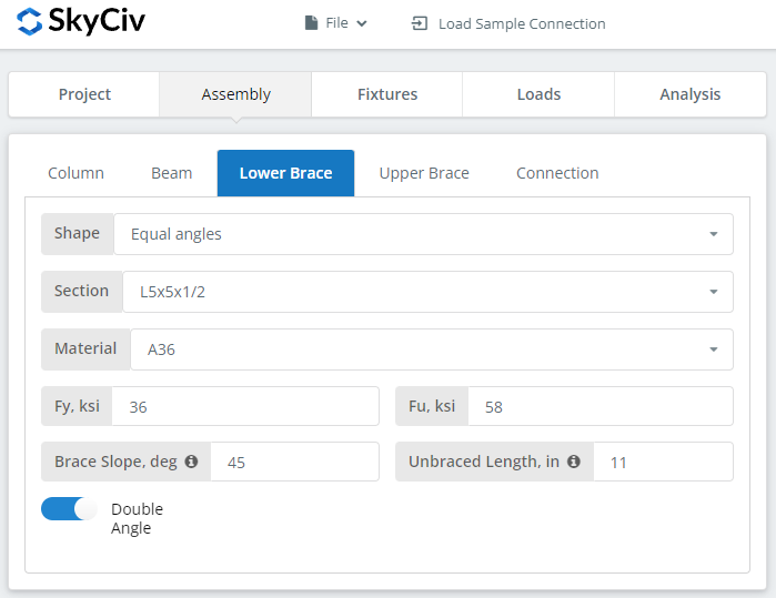
The brace can be a single angle, a double angle, a square or rectangular HSS, or a WT section. The shape drives how the brace meets the gusset. An angle connects through one leg, which puts the load off the brace centreline and brings shear lag into the net section check. An HSS is normally slotted over the plate and welded each side, which keeps the load concentric but needs the slot end checked.
The brace angle matters as much as the section. It sets how the brace force splits into the horizontal and vertical components that the gusset has to deliver, so a shallow brace drives the beam interface and a steep one drives the column interface.
Registerkarte „Verbindung“.
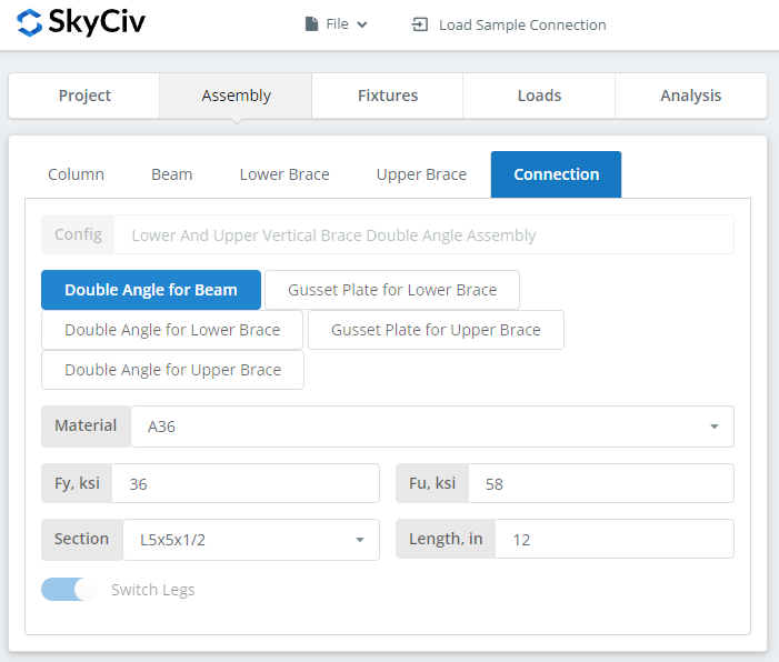
Set the gusset plate and angle properties here. For this example we selected the “Untere und obere Stütze – Doppelter Winkel zur Säule” Fliese.
The gusset has to be deep enough to develop the brace connection and still reach both the beam and the column, so watch the 3D renderer as you size it. Its proportions are not free: the Uniform Force Method sets the interface forces from the gusset geometry, so changing the plate dimensions changes the load split, not just the capacity.
Registerkarte „Befestigungen“.
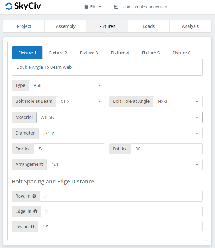
Four interfaces are set here: Balken zur Säule, brace to gusset, gusset to beam, and gusset to column. Each can be bolted or welded, and each is checked separately.
Where an interface is bolted, the bolt grades are A307, A325, A490 oder Benutzerdefiniert. A325 und A490 sind Güten gemäß ASTM F3125, wodurch die älteren eigenständigen Spezifikationen konsolidiert wurden. Where it is welded, Geben Sie das Schweißmaterial an, oder „Benutzerdefiniert“.’ with your own Fnw, and the weld size.
For more on the fastener side, siehe Dokumentation unter Schrauben und Schweißnähte.
Registerkarte Lasten
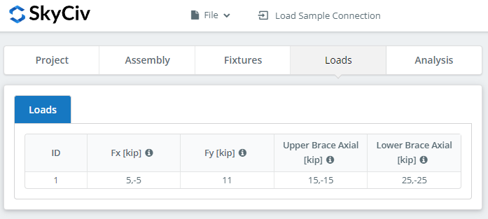
Enter the brace loads and the beam reaction here. Hover the tooltips for the sign convention and direction of each.
Match the loads to the design method you picked at the start. LRFD berücksichtigt faktorisierte Lasten anhand der Bemessungsfestigkeit; ASD nimmt Betriebslasten entgegen der zulässigen Stärke auf. Die Software kann nicht erkennen, was Sie eingegeben haben. Check the brace in compression as well as tension, because the compression case governs the gusset buckling check and often the plate thickness with it.
Registerkarte Ergebnisse
Klicken “Führen Sie Designprüfungen durch”. Alles, was in den früheren Registerkarten fehlt, wird hier markiert und nicht stillschweigend standardmäßig übernommen.
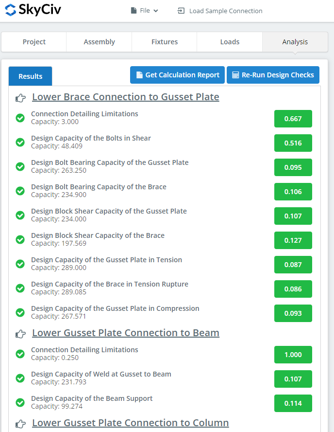
Die Zusammenfassung zeigt, ob die Verbindung erfolgreich war, mit einem Auslastungsgrad für jeden Scheck. Across the four interfaces that covers gusset buckling and tension, Blockschere, Schraubenscherung, bearing and tearout, prying, Schweißkapazität, shear and moment interaction, and the detailing limits on plate thickness and edge distance.
Wenn es fehlgeschlagen ist, Ändern Sie die Eingaben auf den vorherigen Registerkarten und klicken Sie auf “Designprüfungen erneut ausführen”. Wenn es vorbei ist, schwebe über “Bericht” and pick “Kurzbericht” oder “Vollständiger Bericht”.
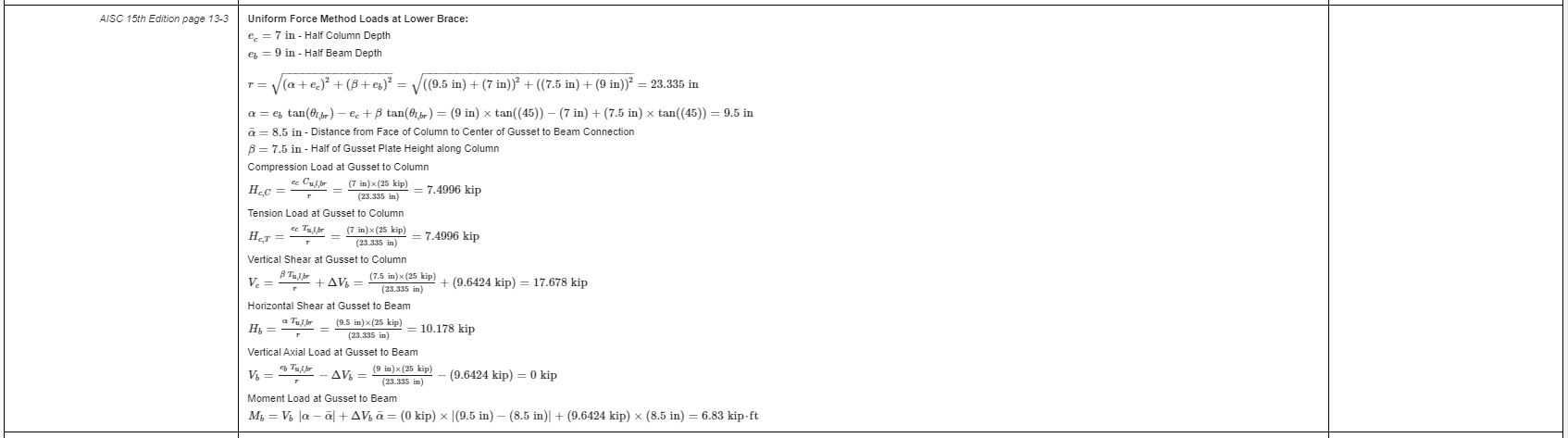
That is an extract from the full report. Jede Prüfung enthält einen Verweis auf das AISC-Handbuch oder die AISC-Spezifikation, und die Arbeit folgt der Reihenfolge, die in der Spezifikation verwendet wird, So kann ein prüfender Ingenieur es Zeile für Zeile lesen, anstatt eine Zahl rückzuentwickeln.
Hierist eine PDF-Kopie des vollständigen detaillierten Berechnungsberichts.
Probieren Sie es selbst aus
Pick the vertical brace, enter your brace, gusset and loads, und sehen Sie sich jeden Scheck mit seiner Codereferenz an. Es läuft im Browser, ohne dass es etwas zu installieren gibt.
Siehe auch die vertical bracing connection calculator, und das chevron brace und Kniestütze calculators for the other bracing configurations.
