
Mit der Plattenabschnittsschnitte tool lets you extract forces, Momente, and other plate results across slabs, Platten, oder Wände. It works in two modes: Schnitt, which reads results along a single line, und Streifen, which integrates results over a defined width. Dies ist nützlich für die Gestaltung von Deckenstreifen, Überprüfung des lokalen Plattenverhaltens, und Überprüfung der Lastverteilung.
So verwenden Sie das Werkzeug zum Schneiden von Plattenabschnitten
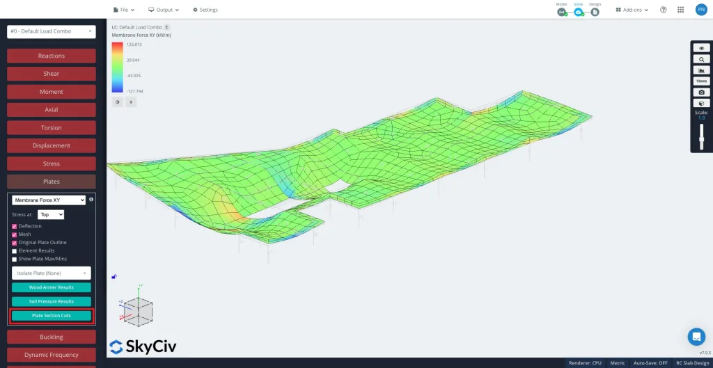
Nach dem Lösen, In der Menüleiste auf der linken Seite Platten und dann Plattenabschnittsschnitte im linken Bereich.
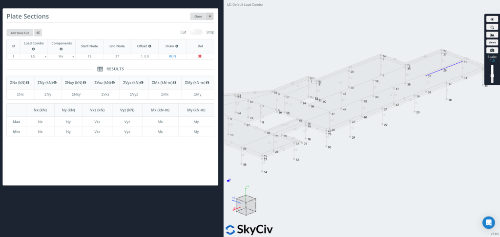
Klicken „Neuen Schnitt hinzufügen“ um einen neuen Eintrag zu erstellen.
Jeder Schnitt beinhaltet:
- Combo laden – Wählen Sie aus, aus welcher Lastkombination Ergebnisse extrahiert werden sollen.
- Komponenten – Wählen Sie den Ergebnistyp. The available components depend on the active mode (Cut or Strip) – see the sections below.
- Knoten starten / Knoten beenden – Definieren Sie das Segment, in dem der Schnitt platziert werden soll. You can also enter coordinates directly, z.B.
[0,0,0]. - Versatz – Optionally shift the cut line. Enter it as
a,b, wo ein is the node ID that sets the offset direction and b is the offset distance (z.B.1, 0.5).- Dies ist nützlich, wenn Sie ein Diagramm mit einem festgelegten Versatz von einer Kante erstellen möchten, ohne die Koordinaten manuell berechnen zu müssen.
Verwenden Sie die Schnitt / Streifen toggle in the top right corner to switch between the two modes. They differ in what they extract and which components are available.
Jetzt können Sie zeichnen & Führen Sie den Schnitt aus
Drücken Sie LAUFEN um den Schnitt zu erzeugen. Die Schnittlinie wird auf Ihrem Modell angezeigt (wie auf der rechten Seite des Bildes gezeigt), und das Ergebnistabelle wird mit Maximal- und Minimalwerten für jede ausgewählte Komponente gefüllt.
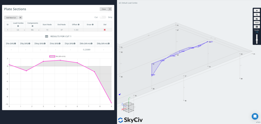
Sie können nun das Diagramm zeichnen direkt auf die Geometrie, Ergebniswerte visuell entlang der Schnittlinie anzeigen.
Cut Mode – Results Along a Line
Im Schnitt mode the tool reads plate results along the cut line and reports them per unit length, together with the summed (Σ) total along the whole cut.
- Komponenten – Nx, Der, Nxy, Vxz, Vyz, Mx, Meine (oder Alle at once), the Wood-Armer design moments (M1 / M2, oben / Unterseite), and Soil Pressure.
- Achsen – Results are reported in each plate’s local axes.
- Einheiten – Force or moment per unit length for the diagram; the results table shows the totals ΣNx … ΣMy along the cut.
Strip Mode – Results Over a Width
Turn on the Streifen toggle in the top right corner to generate a strip section.
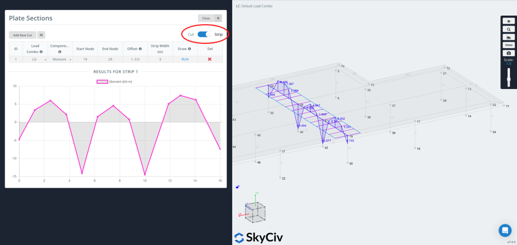
Ein Streifen extrahiert Ergebnisse über eine Breite, not just along a line. At each station along the cut it integrates the plate results across the strip width, so the reported value is the total force or moment carried by that slice of slab. This is typically used for Plattenstreifendesign, where design codes work with forces and moments over a strip of slab rather than at a single point.
Strip axis convention
A strip has a longitudinal axis running from the start node to the end node, and it is treated as an equivalent Trägers along that axis. All plate results are first transformed into this axis and then integrated across the strip width: the bending moment is reported about the strip axis, just as you would read the bending moment of a beam running along it, and the axial, shear and in-plane shear forces are resolved and summed the same way. Kurz gesagt, the distributed plate forces are reduced to the resultant forces and moments that an equivalent beam of that width would carry.
Ein Streifen ist nützlich, wenn Sie ihn brauchen:
- Bemessungswerte für ein- oder zweibahnige Deckenstreifen
- Repräsentativere Werte über einen physischen Streifen als über eine einzelne Linie
- Code-based averaging of peak values (see Peak Moment Ratio below)
Strip-specific inputs
- Strip Width – Enter
Wl,Wrfor an asymmetric strip, wo Wl is the width to the left and Wr the width to the right (viewed from start to end). Enter a single value for a symmetric strip. - Komponenten – Moment, Scheren, Axial, In-plane Shear, und M comb top / M comb bot (combined reinforcement design moments – see below).
- Peak Moment Ratio (Optional) – Enable this option in the settings to cap the peaks of the diagram and distribute the moment more evenly across the strip, as required by code-based averaging such as the CSA two-thirds rule. Enter a ratio between 0 und 1 (1.0 = no capping).
M comb top / M comb bot (combined design moments)
The “M comb” components are the combined Wood-Armer design moments. At every point a plate carries two bending moments and a twisting moment Mxy. Reinforcement bars resist bending along their own direction but not twist, so the twisting moment has to be folded into the bending moments – the Wood-Armer method does this, giving a single equivalent design moment for each reinforcement layer.
oben und Unterseite refer to the two reinforcement layers (the two faces of the plate), and they are defined by the local z-axis of each finite element’s coordinate system: the face the local +z axis points toward is the oben, and the opposite face is the Unterseite. Because the local axes are assigned per element – and depend on how each element is defined and the order of its nodes – check the element local axes in the model to confirm which physical face is top and which is bottom. M comb top sizes the reinforcement near the top face, und M comb bot the reinforcement near the bottom face.
Because the results are integrated across the width, Strip values are reported in force or moment units (not per unit length).
Cut vs Strip – Which to Use
- Benutzen Schnitt for a quick diagram of a result component along a line (in plate axes), or to get the total (Σ) across the cut.
- Benutzen Streifen when you need design forces and moments over a finite width (Plattenstreifendesign), combined reinforcement moments (M comb), or code-based peak averaging.
