
Basisplatten -Designbeispiel unter Verwendung von AISC 360-22 und ACI 318-19
Problemanweisung
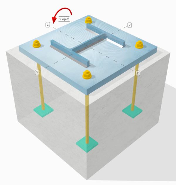
Bestimmen Sie, ob die entworfene Verbindung zu Base-Plattenverbindung für a ausreicht 5 kip-ft strong-axis moment.
Gegebene Daten
Spalte:
Spaltenabschnitt: W8x31
Säulenbereich: 9.130 im2
Säulenmaterial: A992
Grundplatte:
Grundplattenabmessungen: 15 in x 15 im
Grundplattendicke: 1 im
Grundplattenmaterial: A36
Beton:
Konkrete Abmessungen: 18 in x 18 im
Betondicke: 15 im
Betonmaterial: 3000 psi
Schweißnähte:
Schweißnahtgröße: 1/4 im
Füllmetallklassifizierung: E.70XX
Drucklast nur durch Schweißnähte übertragen? NEIN
Modell im kostenlosen SkyCiv-Tool
Modellieren Sie noch heute das oben stehende Grundplattendesign mit unserem kostenlosen Online-Tool! Keine Anmeldung erforderlich.
Determine if Low Moment or Large Moment
The calculations for this base plate example, which is subjected to a strong-axis moment, will be based on AISC-Designhandbuch 1, 3RD Edition. According to the design guide, base plates subjected to moment loads only are classified as the Large Moment Case. This is because no axial load is present to counteract the eccentric load acting on the connection.
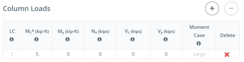
For other load combinations, such as strong-axis bending with axial compression or strong-axis bending with axial tension, determining if the case is Large Moment or Low Moment depends on the actual Spaltengröße, base plate size, concrete size, and the given Ladungen.
In the free version of SkyCiv, the moment case is displayed as you enter the load values. You can access the free tool here to determine the moment case yourself. Straight from the browser, keine Installation erforderlich.
To learn more about Low Moment and Large Moment case, refer to this SkyCiv article: AISC DG1: Grundplatten mit großem Moment und niedrigem Moment
Schritt-für-Schritt-Berechnungen
Prüfen #1: Weld capacity
We start the design by checking the weld capacity of the connection. We use the Blodgett equations from Entwurf von Schweißkonstruktionen von Omer W. Blodgett to determine the weld section modulus of the weld. We take the weld shape shown below as a simplification.
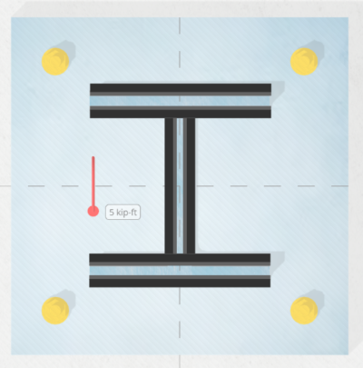
\(S_w = 2d_{col}b_f + \dfrac{(d_{col})^2}{3} = 2 \times 8 \text{ in} \times 8 \text{ in} + \dfrac{(8 \text{ in})^2}{3} = 149.33 \text{ in}^2\)
Als nächstes, we divide the applied bending moment by the weld section modulus to determine the weld stress per unit length. Note that in calculating the weld section modulus, we assume the critical weld stresses occur at the outermost fiber. For a weld in an I-shaped section, the critical locations are at the outer flanges. We get the weld stress as:
\(r_{uw} = \dfrac{M_z}{S_w} = \dfrac{5 \text{ kip·ft}}{149.33 \text{ in}^2} = 0.40179 \text{ kip/in}\)
Dann, wir berechnen die capacity of the weld. Für ein 0.25 in weld size, the design weld throat is 0.177 im, which is obtained by multiplying the weld size by \(\dfrac{\sqrt{2}}{2}\). Verwenden von AISC 360-22 Gl. J2-4, the weld capacity per unit length is:
\(\phi r_n = \phi 0.6F_{exx}E_w k_{ds} = 0.75 \times 0.6 \times 70 \text{ ksi} \times 0.177 \text{ in} \times 1 = 5.5755 \text{ kip/in}\)
Schon seit 0.40179 KPI < 5.5755 KPI , the column weld capacity is ausreichend.
This weld check investigates the weld stress at the tension flange. Since the geometry is symmetric and the only load is a moment acting at the center, we can assume the stress at the compression flange is the same as the stress at the tension flange. Deshalb, the welds at the compression flange also have enough capacity.
In diesem Designbeispiel, jedoch, the design inputs specify that compression is not transferred through the welds, but through Lager. So, in the next check, we evaluate the bearing capacity of the column.
Prüfen #2: Calculate column bearing capacity
After evaluating the weld capacity, we make sure the column has enough capacity to bear on the base plate. This is necessary because we assume the welds do not carry the compression load.
Zuerst, Wir bestimmen die compressive stress at the critical section, which is still the flange. We then add any contribution from axial compression. In diesem Fall, there is none.
\(r_u = \dfrac{N_x}{A_{col}} + \dfrac{M_z 0.5d_{col}}{I_{zz,col}} = \dfrac{0 \text{ kip}}{9.13 \text{ in}^2} + \dfrac{5 \text{ kip·ft} \times 0.5 \times 8 \text{ in}}{110 \text{ in}^4} = 2.1818 \text{ ksi}\)
Dann, Wir verwenden AISC 360-22 Section J7 Eq. J7-1 zu bestimmen Tragfähigkeit:
\(\phi r_n = \phi 1.8F_{y\_col} = 0.75 \times 1.8 \times 50 \text{ ksi} = 67.5 \text{ ksi}\)
Schon seit 2.1818 KSI < 67.5 KSI, Die Säulenlagerkapazität ist ausreichend.
Üblicherweise, this check is not governing.
Prüfen #3: Berechnen Sie die Betonlagerkapazität
To calculate the concrete bearing capacity, we need two areas. See the figure below as a guide.
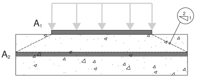
- A1 – Base plate loaded area
- A2 – Area of the concrete support with the same shape as A1
A1 ist der loaded area of the base plate, während A2 ist der same loaded area projected at a 2H:1V slope into the concrete support. More details on these areas can be found in ACI 318-19 Sektion 22.8.3.2.
In diesem base plate design with moment, the A1 area will be calculated using the full width of the base plate, \(B\) und das actual bearing length, \(Y\). The actual bearing length is measured from the edge of the base plate at the compression side towards the center of the plate.
\( A_1 = B \times Y \)
For most engineers, calculating A1 and A2 requires a lot of work, so they simply assume A1 = A2, was konservativ ist. In dem SkyCiv Base Plate-Software, Iterationen are performed to determine the actual A1 values and to maximize the capacity of the base plate.
The table below shows the iteration steps from SkyCiv to determine the bearing length Y, und folglich, to determine the actual A1 and A2 areas.

Zuerst, an initial Y is assumed, and the A2 and A1 values are calculated based on the initial Y. These are then used to calculate the maximum bearing strength of the concrete, \(f_{p\_max}\), und das entsprechende bearing force per unit length, \(q_{max}\). Once these are determined, the corresponding Y value is determined based on Gl. 4-32 of AISC DG1 3rd Auflage. If the calculated Y does not match the initial Y, another iteration step is performed. A more detailed step-by-step calculation of the last iteration is shown in the next section.
Jetzt, taking the A2 and A1 values from the iteration, Wir verwenden Gl. 4-2 of AISC Design Guide 1, 3RD Edition, to determine \(f_{p\_max}\), the design bearing strength for concrete crushing:
\(f_{p\_max} = \phi \left( \min \left( 0.85 \, (f_c’) \sqrt{\dfrac{A_2}{A_1}}, \, 1.7 \, (f_c’) \right) \right)\)
\(f_{p\_max} = 0.65 \times \left( \min \left( 0.85 \times (3 \text{ ksi}) \times \sqrt{39.941}, \, 1.7 \times (3 \text{ ksi}) \right) \right) = 3.315 \text{ ksi}\)
zusätzlich, since this design is a Large Moment Case, the base plate has both a compression side and a tension side. In dieser Situation, we should allow the concrete bearing to be at its full capacity and minimize the Y value. So, any remaining tensile force, based on equilibrium of forces, will be taken by the anchors at the tension side.
Given this, we set \(f_{p\_actual}\) gleich \(f_{p\_max}\).
\(f_{p\_actual} = f_{p\_max} = 3.315 \text{ ksi}\)
Schon seit 3.315 ksi ≤ 3.315 KSI, Die Betonlagerkapazität ist ausreichend.
Prüfen #4: Calculate base plate yielding capacity at the bearing interface
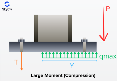
The next step is to determine if the base plate has enough capacity for the given load. As the moment load pushes the base plate against the concrete, the base plate has a tendency to yield due to flexure. We call this check the base plate yielding check on the bearing interface. There is also a separate yielding due to the tension load, and it will be covered in the next design check.
To check the base plate yielding, we need to determine the \(q_{max}\), which is the compression force per unit length. AISC DG1 3rd Ed. Gl. 4-37 gibt \(q_{max}\)wie:
\(q_{max} = f_{p\_max}B_{bp} = 3.315 \text{ ksi} \times 15 \text{ in} = 49.725 \text{ kip/in}\)
Dann, we will calculate the Y-dimension. Although the Y-dimension is already calculated in the prior check, this section will show how we use the equations from AISC DG1. For this Large Moment Case, Wir verwenden Gl. 4-32 of AISC DG1, 3RD Edition.
For the plus case:
\(Y_{case1} = \left( f + \dfrac{L_{bp}}{2} \right) + \sqrt{\left( \left( f + \dfrac{L_{bp}}{2} \right)^2 \right) – \dfrac{2M_z}{q_{max}}}\)
\(Y_{case1} = \left( 5.5315 \text{ in} + \dfrac{15 \text{ in}}{2} \right) + \sqrt{\left( \left( 5.5315 \text{ in} + \dfrac{15 \text{ in}}{2} \right)^2 \right) – \dfrac{2 \times 5 \text{ kip·ft}}{49.725 \text{ kip/in}}}\)
\(Y_{case1} = 25.97 \text{ in}\)
For the minus case:
\(Y_{case2} = \left( f + \dfrac{L_{bp}}{2} \right) – \sqrt{\left( \left( f + \dfrac{L_{bp}}{2} \right)^2 \right) – \dfrac{2M_z}{q_{max}}}\)
\(Y_{case2} = \left( 5.5315 \text{ in} + \dfrac{15 \text{ in}}{2} \right) – \sqrt{\left( \left( 5.5315 \text{ in} + \dfrac{15 \text{ in}}{2} \right)^2 \right) – \dfrac{2 \times 5 \text{ kip·ft}}{49.725 \text{ kip/in}}}\)
\(Y_{case2} = 0.092925 \text{ in}\)
Note that this equation has + und – Symbole, so we get two values. Von hier, we need to determine which value makes more sense. Schon seit 25.97 im is greater than the base plate length, 15 im, we will not consider this value. So, wir werden verwenden 0.092925 im als die Lagerlänge.
\(Y = Y_{case2} = 0.092925 \text{ in}\)
Als nächstes, we calculate the cantilever lengths. Dies sind die m and n dimensions from the figure below. Dies basiert auf AISC DG1 3rd Edition Section 4.3.1.
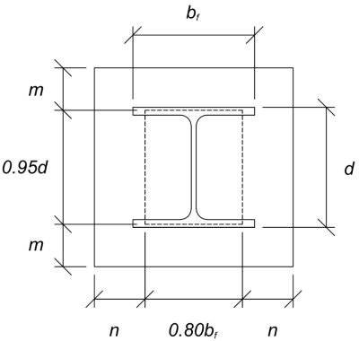
The calculated m and n cantilever values are:
\(m = \dfrac{L_{bp} – 0.95d_{col}}{2} = \dfrac{15 \text{ in} – 0.95 \times 8 \text{ in}}{2} = 3.7 \text{ in}\)
\(n = \dfrac{B_{bp} – 0.8b_f}{2} = \dfrac{15 \text{ in} – 0.8 \times 8 \text{ in}}{2} = 4.3 \text{ in}\)
Dann, wir werden compare the calculated Y value to the larger of m and n. Since Y is less than the larger cantilever length, wir werden verwenden AISC DG1 3rd Ed. Gl. 4-52ein. This gives the required base plate thickness to be:
\(t_{p(req)} = \sqrt{\dfrac{4f_{p\_actual}Y \left( n – \dfrac{Y}{2} \right)}{\phi F_{y\_bp}}}\)
\(t_{p(req)} = \sqrt{\dfrac{4 \times 3.315 \text{ ksi} \times 0.092925 \text{ in} \times \left( 4.3 \text{ in} – \dfrac{0.092925 \text{ in}}{2} \right)}{0.9 \times 36 \text{ ksi}}} = 0.4022 \text{ in}\)
Schließlich, let’s compare it to the actual base plate thickness.
\(t_{p(actual)} = t_{bp} = 1 \text{ in}\)
Schon seit 0.4022 im < 1 im, the yielding capacity of the base plate is ausreichend.
Prüfen #5: Calculate base plate yielding capacity at the tension interface
The required tensile force on the anchors at the tension side is equal to the resulting compression force on the compression side. This is because the base plate is only loaded with moment loads, and so the resulting couple forces are equal in magnitude.
To calculate the required strength of anchors, Wir verwenden AISC DG1 3rd Ed. Gl. 4-31.
\(T_u = q_{max}Y = 49.725 \text{ kip/in} \times 0.092925 \text{ in} = 4.6207 \text{ kip}\)
Dann, wir berechnen die eccentricity of this tensile force from the column support. This is taken from the center of the anchor rod to the center of the column flange. Wir verwenden Gl. 4-61 of the design guide to determine the eccentricity. In the equation, f is the distance of the anchor rod from the column centerline.
\(x = \left( f – \dfrac{d_{col}}{2} \right) + \dfrac{t_f}{2} = \left( 5.5315 \text{ in} – \dfrac{8 \text{ in}}{2} \right) + \dfrac{0.435 \text{ in}}{2} = 1.749 \text{ in}\)
Note that in this analysis, we take the whole base plate width as the section to resist the flexure, as we closely follow the AISC DG1 3rd Ed. guidelines. Other conservative bending widths could also be used.
Schließlich, we determine the required base plate thickness mit Gl. 4-62ein.
\(t_{p(req)} = \sqrt{\dfrac{4T_u x}{B_{bp}\phi F_{y\_bp}}} = \sqrt{\dfrac{4 \times 4.6207 \text{ kip} \times 1.749 \text{ in}}{15 \text{ in} \times 0.9 \times 36 \text{ ksi}}} = 0.25791 \text{ in}\)
Schon seit 0.25791 im < 1 im, bleibt die yielding capacity of the base plate is ausreichend.
Prüfen #6: Ankerprüfungen
The rest of the anchor design checks are not shown in this example. Please refer to other SkyCiv Base Plate Design Examples that covers capacity of Anchorage.
Entwurfszusammenfassung
Die Skyciv-Basisplattentwurfsoftware kann automatisch einen schrittweisen Berechnungsbericht für dieses Entwurfsbeispiel erstellen. Es enthält auch eine Zusammenfassung der durchgeführten Schecks und deren resultierenden Verhältnisse, Die Informationen auf einen Blick leicht zu verstehen machen. Im Folgenden finden Sie eine Stichprobenzusammenfassungstabelle, Welches ist im Bericht enthalten.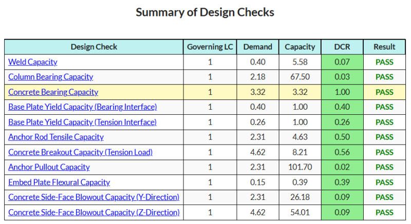
Basisplattensoftware kaufen
Kaufen Sie die Vollversion des Basisplatten -Designmoduls selbst ohne andere Skyciv -Module selbst. Auf diese Weise erhalten Sie einen vollständigen Satz von Ergebnissen für die Basisplattendesign, Einbeziehung detaillierter Berichte und mehr Funktionen.

