AISCを使用したベースプレートのデザイン例 360-22 およびACI 318-19
問題ステートメント
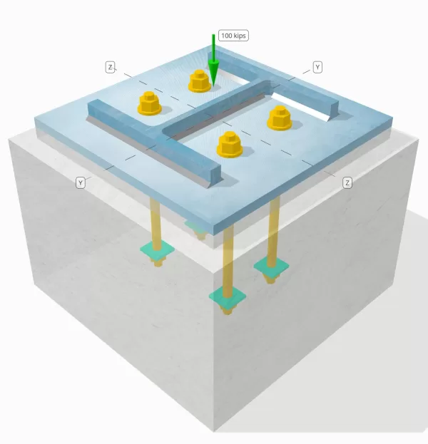
設計されたカラムツーベースプレート接続が100キップの圧縮負荷に十分であるかどうかを判断します.
指定されたデータ
カラム:
列セクション: W12x96
列エリア: 28.200 に2
列素材: A992
ベースプレート:
ベースプレートの寸法: 18 xで 18 に
ベースプレートの厚さ: 3/4 に
ベースプレート材料: A36
コンクリート:
具体的な寸法: 21 xで 21 に
コンクリートの厚さ: 14 に
コンクリート材料: 3000 psi
溶接:
溶接サイズ: 5/16 に
フィラー金属分類: E70XX
溶接のみを介して伝達される圧縮負荷? はい
SkyCiv 無料ツールでモデルを作成する
無料のオンライン ツールを使用して、上記のベース プレート設計を今すぐモデル化してください。! サインアップは必要ありません.
段階的な計算
小切手 #1: 列のベアリング容量を計算します
通常、カラムの負荷は直接ベアリングを介してベースプレートに転送されます.
最初に計算することから始めます 列のベアリング容量 を使用して AISC 360-22 Eq. J7-1:
\(\phi r_n = phi 1.8 F_{および _col} A_{col} = 0.75 \回 1.8 \回 50 \テキスト{ KSI} \回 28.2 \テキスト{ に}^2 = 1903.5 \テキスト{ キップ}\)
以来 100 キップ < 1903.5 キップ, 列ベアリング容量はです 十分な.
さらに, 完全な圧縮荷重が溶接を介して転送されるため, 完全な接触ベアリング表面に従って AISC 360-22 第M4.4章 必要ありません. 溶接に負荷を伝達するのに十分な容量があることを確認する必要があります.
小切手 #2: 溶接容量を計算します
溶接容量を評価します, 最初に決定します 総溶接長 列の寸法に基づいています:
\( L_{溶接} = 2b_f + 2 \左( d_{col} – 2T_F – 2r_{col} \正しい) + 2 \左( B_F – t_w – 2r_{col} \正しい) \)
\( L_{溶接} = 2 \回 12.2 \テキスト{ に} + 2 \倍左( 12.7 \テキスト{ に} – 2 \回 0.9 \テキスト{ に} – 2 \回 0.6 \テキスト{ に} \正しい) + 2 \倍左( 12.2 \テキスト{ に} – 0.55 \テキスト{ に} – 2 \回 0.6 \テキスト{ に} \正しい) = 64.7 \テキスト{ に} \)
これで, これで計算できます 溶接のインチあたりの応力, と仮定します 100-KIP負荷は均等に分散されています:
\( r_u = frac{N_X}{L_{溶接}} = frac{100 \テキスト{ キップ}}{64.7 \テキスト{ に}} = 1.5456 \テキスト{ kip/in} \)
その後, を決定します 長さごとに溶接容量 を使用して AISC 360-22 Eq. J2-4:
\( \Phi R_{ん} = phi 0.6 F_{exx} E_{w} k_{DS} = 0.75 \回 0.6 \回 70 \テキスト{ KSO} \回 0.221 \テキスト{ に} \ 回 1 = 6.9615 \テキスト{ kip/in}\)
以来 1.54 KPI < 6.96 KPI, 溶接容量はです 十分な.
小切手 #3: 圧縮荷重によるベースプレートの曲げ容量を計算する
ベースプレートの曲げ能力はその寸法に依存します. プレートが広すぎる場合, 厚い材料が必要です. 特定の負荷に対して適切なベースプレートサイズを選択するには、経験が必要です, また、複数の計算を実行するのは時間がかかる場合があります. の SkyCYVベースプレート設計ソフトウェア このプロセスを簡素化します, わずか数秒で高速かつ効率的なモデリングと分析を有効にする.
最初, を決定します 重要なカンチレバーの長さ, これは大きい方です 寸法m そして 寸法n. また、それ以上であってはなりません \( \フラク{ \平方根{d_{col}=最も近いサポートの面までのせん断が考慮されているセクションの距離{f}}}{4} \).
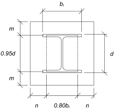
\( l = max 左( \フラク{L_{血圧} – 0.95 d_{col}}{2}, \フラク{b_{血圧} – 0.8 =最も近いサポートの面までのせん断が考慮されているセクションの距離{f}}{2},\フラク{ \平方根{d_{col}=最も近いサポートの面までのせん断が考慮されているセクションの距離{f}}}{4} \正しい) \)
\( l = max 左( \フラク{18 \テキスト{ に} – 0.95 \時間12.7 テキスト{ に}}{2}, \フラク{18 \テキスト{ に} – 0.8 \回 12.2 \テキスト{ に}}{2},\フラク{ \平方根{18 \テキスト{ に} \回 12.2 \テキスト{ に}}}{4} \正しい)\)
\(l = 4.12 \テキスト{ に}\)
臨界長が識別されると, を計算します 単位長さごとに適用されたモーメント, 完全な圧縮荷重がベースプレート領域に均一に分布していると仮定します:
\( m_{あなた} = left( \フラク{N_{バツ}}{b_{血圧} L_{血圧}}\正しい) \左( \フラク{l^{2}}{2}\正しい)\)
\( m_{あなた} = left( \フラク{100 \テキスト{ キップ}}{18 \テキスト{ に} \回 18 \テキスト{ に}}\正しい) \倍左( \フラク{4.12 \テキスト{ に}^ 2}{2}\正しい)\)
今, を使用して AISC 360-22 Eq. F2-1, 計算します 単位長さあたりの曲げ容量:
\(\映画_{ん} = phi f_{および _bp}\左(\フラク{t_{血圧}^{2}}{4}\正しい) = 0.9 \回 36 \テキスト{ KSI} \倍左(\フラク{\左(0.75 \テキスト{ に}\正しい)^ 2}{4}\正しい) = 4.5562 \テキスト{ Kip-in/in}\)
以来 2.62 Kip-in/in < 4.55 Kip-in/in, ベースプレートの曲げ能力はです 十分な.
小切手 #4: コンクリートベアリング容量
最終チェックは、コンクリートが適用された負荷をサポートできることを保証します. 一方、より広いコンクリートベースはベアリング容量を増加させます, 効率的な設計は、強度と費用対効果のバランスをとる必要があります. 今, 具体的なサポートに十分な能力があるかどうかを判断しましょう.
始めること, を決定します ベアリングエリア:
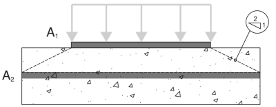
A1 - ベースプレートベアリングエリア
A2 - 具体的なサポートベアリングエリア, aで投影 2:1 スロープ
\(A_1 = L_{血圧} b_{血圧} = 18 \, \テキスト{に} \回 18 \, \テキスト{に} = 324 \, \テキスト{に}^2)
\(A_2 = n_{A_2} b_{A_2} = 21 \, \テキスト{に} \回 21 \, \テキスト{に} = 441 \, \テキスト{に}^2)
そこから, 適用します AISC 360-22 Eq. J8-2 コンクリートベアリング容量を計算します:
\(\phi p_p = phi 左( \min 左( 0.85 \, f’_c \, A_1 SQRT{\フラク{A_2}{A_1}}, \, 1.7 \, f’_c \, A_1 右) \正しい)\)
\(\phi p_p = 0.65 \倍左( \min 左( 0.85 \回 (3 \, \テキスト{KSI}) \回 324 \, \テキスト{に}^2 times sqrt{\フラク{441 \, \テキスト{に}^ 2}{324 \, \テキスト{に}^ 2}}, \, 1.7 \回 (3 \, \テキスト{KSI}) \回 324 \, \テキスト{に}^2 右) \正しい)\)
\(\phi p_p = 626.54 \, \テキスト{キップ}\)
以来 100 キップ < 626.54 キップ, コンクリートベアリング能力はです 十分な.
設計の概要
Skycivベースプレート設計ソフトウェアは、このデザインの例の段階的な計算レポートを自動的に生成できます. また、実行されたチェックとその結果の比率の概要も提供します, 情報を一目で理解しやすくします. 以下はサンプルの概要表です, レポートに含まれています.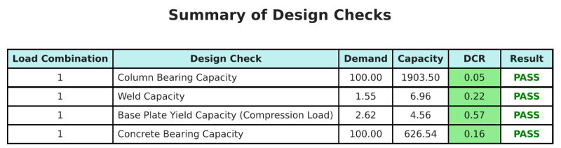
SkyCIVサンプルレポート
SkyCiv ベース プレート設計レポートから期待できる詳細レベルと明瞭さのレベルを確認してください。. The report includes all key design checks, 方程式, 結果は明確で読みやすい形式で表示されます. It is fully compliant with design standards. SkyCiv ベース プレート カリキュレーターを使用して生成されたサンプル レポートを表示するには、以下をクリックしてください。.
ベースプレートソフトウェアを購入します
他のSkyCIVモジュールなしで、ベースプレートデザインモジュールのフルバージョンを単独で購入する. これにより、ベースプレートデザインの完全な結果が得られます, 詳細なレポートとその他の機能を含む.