ENを使用したベースプレートデザインの例 1993-1-8-2005, に 1993-1-1-2005 およびEN 1992-1-1-2004
問題ステートメント
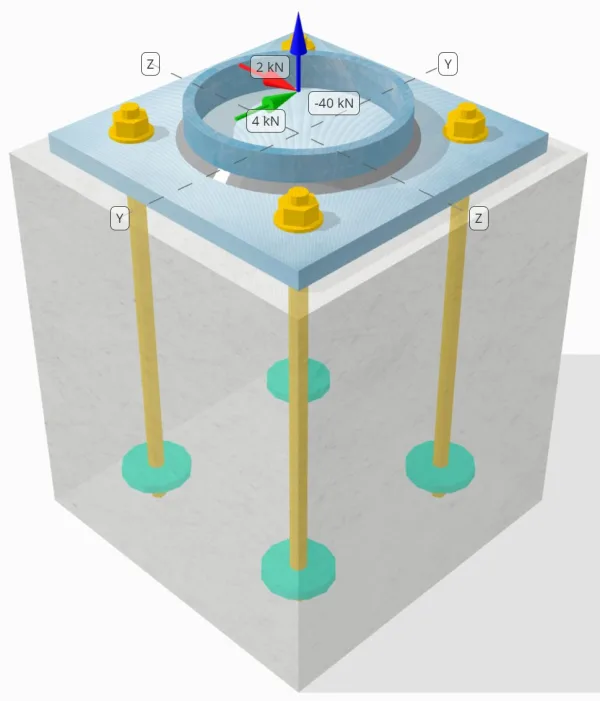
設計された柱とベース プレートの接続が十分な接続であるかどうかを判断します。 50-kN引張荷重, 4-kN Vyせん断荷重, そして 2-kN Vz せん断荷重.
指定されたデータ
カラム:
列セクション: CHS193.7×10
列エリア: 5770.0 mm²
列素材: S460
ベースプレート:
ベースプレートの寸法: 300mm×300mm
ベースプレートの厚さ: 18んん
ベースプレート材料: S235
グラウト:
グラウトの厚さ: 0 んん
コンクリート:
具体的な寸法: 350mm×350mm
コンクリートの厚さ: 400 んん
コンクリート材料: C35/45
ひび割れまたは破損していません: 割れた
アンカー:
アンカーの直径: 16 んん
効果的な埋め込み長: 350 んん
埋め込まれたプレートの直径: 70 んん
埋め込まれたプレートの厚さ: 10 んん
アンカー素材: 4.8
溶接:
溶接タイプ: フィレット
溶接サイズ: 7んん
フィラー金属分類: E42
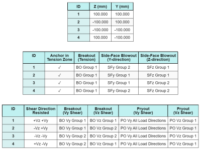
アンカーデータ (から SkyCIV計算機):
SkyCiv 無料ツールでモデルを作成する
無料のオンライン ツールを使用して、上記のベース プレート設計を今すぐモデル化してください。! サインアップは必要ありません.
ノート
この設計例の目的は、同時せん断荷重とアキシアル荷重を含む容量チェックのための段階的な計算を実証することです。. 必要なチェックの一部については、前の設計例ですでに説明しました。. 各セクションに記載されているリンクを参照してください.
段階的な計算
小切手 #1: 溶接容量を計算します
完全な 引張荷重 に抵抗されている 溶接部全体, ながら せん断荷重コンポーネント 溶接全長の一部にのみ分布します. この部分は、 90°セクター 柱の中心から円周まで. したがって, のみ 全周の半分 せん断荷重に耐えるように設計されています.
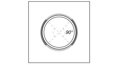
まず最初に計算します 総溶接長 そしてその 溶接部分 90°投影内.
\(L_{溶接,満杯} = pi d_{col} = pi 回 193.7\ \テキスト{んん} = 608.53\ \テキスト{んん}\)
\(L_{溶接} = frac{\ピド_{col}}{2} = frac{\円周率倍 193.7\ \テキスト{んん}}{2} = 304.26\ \テキスト{んん}\)
次, を計算します 合成せん断荷重.
\(V_r = sqrt{(v_y)^ 2 + (V_Z)^ 2} = sqrt{(4\ \テキスト{kN})^ 2 + (2\ \テキスト{kN})^ 2} = 4.4721\ \テキスト{kN}\)
次に、 正常 そして せん断応力, 想定される負荷分散を考慮して.
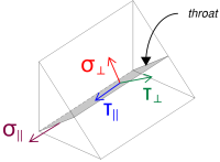
\( \シグマ_{\perp} = frac{N_X}{L_{溶接,満杯}\,a,sqrt{2}} = frac{40\ \テキスト{kN}}{608.53\ \テキスト{んん} \回 4.95\ \テキスト{んん} \回 sqrt{2}} = 9.39\ \テキスト{MPa} \)
\( \君の_{\perp} = frac{N_X}{L_{溶接,満杯}\,a,sqrt{2}} = frac{40\ \テキスト{kN}}{608.53\ \テキスト{んん} \回 4.95\ \テキスト{んん} \回 sqrt{2}} = 9.39\ \テキスト{MPa} \)
\( \君の_{\平行} = frac{V_r}{L_{溶接}\,a} = frac{4.4721\ \テキスト{kN}}{304.26\ \テキスト{んん} \回 4.95\ \テキスト{んん}} = 2.9693\ \テキスト{MPa} \)
その後, を計算します 複合応力 を使用して に 1993-1-8:2005 Eq. (4.1).
\(F_{w,エド1} = sqrt{(\シグマ_{\perp})^ 2 + 3\大きい((\君の_{\perp})^ 2 + (\君の_{\平行})^2big)}\)
\(F_{w,エド1} = sqrt{(9.39\ \テキスト{MPa})^ 2 + 3\大きい((9.39\ \テキスト{MPa})^ 2 + (2.9693\ \テキスト{MPa})^2big)}\)
\(F_{w,エド1} = 19.471\ \テキスト{MPa}\)
同時に, を決定します 母材にかかる応力 同じ方程式を使用して.
\(F_{w,エド2} = シグマ_{\perp} = 9.39\ \テキスト{MPa}\)
次, を計算します 溶接能力. まず最初に決定するのは、 極限引張強さ (NDSに準拠したビーム安定係数) の 弱い素材, そして使用します に 1993-1-8:2005 Eq. (4.1) を得るために すみ肉溶接抵抗 そして 卑金属抵抗.
\(f_u = \min\!\左(F_{あなた,\テキスト{col}},\ f_{あなた,\テキスト{血圧}},\ f_{あなた,w}\正しい) = \min\!\左(550\ \テキスト{MPa},\ 360\ \テキスト{MPa},\ 500\ \テキスト{MPa}\正しい) = 360\ \テキスト{MPa}\)
\(F_{w,RD1} = frac{f_u}{\beta_w\,(\それを計算するために{M2,\text{溶接}})} = frac{360\ \テキスト{MPa}}{0.8 \回 (1.25)} = 360\ \テキスト{MPa}\)
\(F_{w,Rd2} = frac{0.9\,f_u}{\それを計算するために{M2,\text{溶接}}} = frac{0.9 \回 360\ \テキスト{MPa}}{1.25} = 259.2\ \テキスト{MPa}\)
以来 19.471 MPa < 360 MPa, 溶接容量はです 十分な.
小切手 #2: 張力負荷によるベースプレートの曲げ容量を計算する
ベース プレートの曲げ降伏能力の設計例は、「張力に関するベース プレートの設計例」ですでに説明されています。. 段階的な計算については、このリンクを参照してください。.
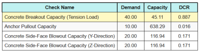
小切手 #3: コンクリートのブレイクアウト容量を緊張して計算します
引張荷重によるブレークアウト時のコンクリートの容量の設計例は、引張用のベース プレートの設計例ですでに説明されています。. 段階的な計算については、このリンクを参照してください。.
小切手 #4: アンカープルアウト容量を計算します
アンカーの引き抜き能力の設計例は、「張力のベース プレート設計例」ですでに説明されています。. 段階的な計算については、このリンクを参照してください。.
小切手 #5: y方向のサイドフェイスブローアウト容量を計算します
Y 方向の側面噴出能力の設計例は、張力のベース プレート設計例ですでに説明されています。. 段階的な計算については、このリンクを参照してください。.
小切手 #6: Z方向のサイドフェイスブローアウト容量を計算します
Z 方向の側面噴出能力の設計例は、張力のベース プレート設計例ですでに説明されています。. 段階的な計算については、このリンクを参照してください。.
小切手 #7: アンカー穴におけるベースプレート支持力の計算 (vy shear)
Vy せん断に対するアンカー穴内のベース プレートの支持力の設計例は、「圧縮およびせん断に対するベース プレートの設計例」ですでに説明されています。. 段階的な計算については、このリンクを参照してください。.
小切手 #8: アンカー穴におけるベースプレート支持力の計算 (VZせん断)
Vz せん断に対するアンカー穴内のベース プレートの支持力の設計例は、「圧縮およびせん断に対するベース プレートの設計例」ですでに説明されています。. 段階的な計算については、このリンクを参照してください。.
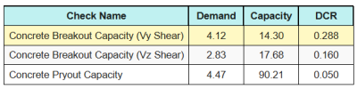
小切手 #9: コンクリートのブレークアウト能力を計算する (vy shear)
Vy せん断によるブレークアウト破壊におけるコンクリート耐力の設計例は、せん断用のベース プレートの設計例ですでに説明されています。. 段階的な計算については、このリンクを参照してください。.
小切手 #10: コンクリートのブレークアウト能力を計算する (VZせん断)
Vz せん断によるブレークアウト破壊におけるコンクリート耐力の設計例は、せん断用のベース プレートの設計例ですでに説明されています。. 段階的な計算については、このリンクを参照してください。.
小切手 #11: プラアウト能力の計算
コンクリートの押し出し能力の設計例は、せん断用のベース プレートの設計例ですでに説明されています。. 段階的な計算については、このリンクを参照してください。.
小切手 #12: アンカーロッドのせん断耐力を計算する
の効果 引張荷重 このチェックでは、アンカーロッドの容量が考慮されます。 せん断力はレバーアームで作用します. しかしながら, この例では, せん断作用 レバーアームなし. したがって, アンカーロッドにかかるせん断応力と引張応力の間の相互作用は、 インタラクションチェック.
レバーアームを使用しないせん断耐力の段階的な計算用, このリンクを参照してください.
SkyCiv ベース プレート設計ソフトウェアは、せん断荷重がレバー アームの有無で作用するかどうかを判断するために必要なすべてのチェックを実行できます。. あなたはできる 無料ツールを試してみる 今日.
小切手 #13: アンカー鋼相互作用チェックの計算
使用します に 1992-4:2018 テーブル 7.3 Eq. (7.54) を評価する せん断応力と引張応力の間の相互作用 アンカーロッドの上に. 引張応力と容量、およびせん断応力と容量を方程式に代入すると、, 結果として生じる インタラクション価値 です:
\(私_{整数} = left(\フラク{N_{エド}}{N_{Rd,s}}\正しい)^ 2 + \左(\フラク{V_{エド}}{V_{Rd,s}}\正しい)^2)
\(私_{整数} = left(\フラク{10\ \テキスト{kN}}{49.22\ \テキスト{kN}}\正しい)^ 2 + \左(\フラク{1.118\ \テキスト{kN}}{38.604\ \テキスト{kN}}\正しい)^2 = 0.042117\)
以来 0.042 < 1.0, アンカーロッド鋼破壊相互作用チェックは 十分な.
小切手 #14: 具体的な故障相互作用チェックの計算
追加の インタラクションチェック には必要です 具体的な失敗 せん断荷重と引張荷重を同時に受ける場合. このため, を使用しております に 1992-4:2018 テーブル 7.3 Eq. (7.55) そして Eq. (7.56).
すべての結果の比率は次のとおりです 引張チェック.
すべての結果の比率は次のとおりです シアーチェック.
最初, を使用してチェックします Eq. (7.55) そしてその結果を インタラクションの最大制限 1.0.
\(私_{\テキスト{ケース1}} = left(\左(\フラク{N_{エド}}{N_{Rd}}\正しい)^{1.5}\正しい) + \左(\左(\フラク{V_{エド}}{V_{Rd}}\正しい)^{1.5}\正しい)\)
\(私_{\テキスト{ケース1}} = left(\左(\フラク{40}{45.106}\正しい)^{1.5}\正しい) + \左(\左(\フラク{4.1231}{14.296}\正しい)^{1.5}\正しい) = 0.99\)
次, を使用してチェックします Eq. (7.56) そしてその結果を インタラクションの最大制限 1.2.
\(私_{\テキスト{ケース2}} = frac{N_{エド}}{N_{Rd}} + \フラク{V_{エド}}{V_{Rd}} = frac{40}{45.106} + \フラク{4.1231}{14.296} = 1.1752\)
以来 0.99 < 1.0 そして 1.175 < 1.2, の 具体的な障害相互作用チェック です 十分な.
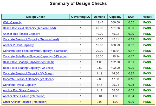
設計の概要
の SkyCYVベースプレート設計ソフトウェア このデザインの例の段階的な計算レポートを自動的に生成できます. また、実行されたチェックとその結果の比率の概要も提供します, 情報を一目で理解しやすくします. 以下はサンプルの概要表です, レポートに含まれています.
SkyCIVサンプルレポート
SkyCiv ベース プレート設計レポートから期待できる詳細レベルと明瞭さのレベルを確認してください。. The report includes all key design checks, 方程式, 結果は明確で読みやすい形式で表示されます. It is fully compliant with design standards. SkyCiv ベース プレート カリキュレーターを使用して生成されたサンプル レポートを表示するには、以下をクリックしてください。.
(サンプルレポートは近日中に追加予定)
ベースプレートソフトウェアを購入します
他のSkyCIVモジュールなしで、ベースプレートデザインモジュールのフルバージョンを単独で購入する. これにより、ベースプレートデザインの完全な結果が得られます, 詳細なレポートとその他の機能を含む.