Esempio di design della piastra di base utilizzando AISC 360-22 e ACI 318-19
Dichiarazione del problema
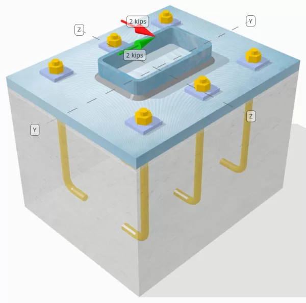
Determinare se la connessione a piastra da colonna a base progettata è sufficiente per a Vy=2-kip e Vz=2-kip carichi di taglio.
Dati dati
Colonna:
Sezione colonna: HSS7X4X5/16
Area colonna: 7.59 pollici2
Materiale colonna: A36
Piastra di base:
Dimensioni della piastra di base: 12 in x 14 pollici
Spessore della piastra di base: 3/4 pollici
Materiale della piastra di base: A36
Malta:
Spessore della malta: 0.25 pollici
Calcestruzzo:
Dimensioni concrete: 12 in x 14 pollici
Spessore di cemento: 10 pollici
Materiale di cemento: 3000 psi
Crackato o non collocato: Rotto
Ancore:
Diametro dell'ancora: 1/2 pollici
Efficace lunghezza dell'incorporamento: 8 pollici
Spessore della rondella della piastra: 0.25 pollici
Attacco rondella piastra: Saldato alla piastra di base
saldature:
Dimensione della saldatura: 1/4 pollici
Classificazione del metallo di riempimento: E70XX
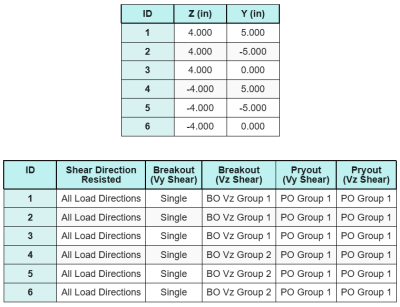
Dati di ancoraggio (a partire dal Calcolatore Skyciv):
Modello nello strumento gratuito SkyCiv
Modella il design della piastra di base qui sopra utilizzando il nostro strumento online gratuito oggi stesso! Non è richiesta la registrazione.
Definizioni
Percorso di carico:
La progettazione segue le raccomandazioni di Guida alla progettazione AISC 1, 3Rd Edition, e ACI 318-19. I carichi di taglio applicati alla colonna vengono trasferiti alla piastra di base attraverso le saldature, e poi al calcestruzzo portante attraverso il aste di ancoraggio. In questo esempio non sono considerati attrito e alette di taglio, Poiché questi meccanismi non sono supportati nell'attuale software.
Per impostazione predefinita, l'applicato il carico di taglio è distribuito su tutti gli ancoraggi, sia attraverso l'uso di rondelle saldate che con altri mezzi tecnici. Il carico trasportato da ciascun ancoraggio viene determinato utilizzando i tre (3) casi indicati in ACI 318-19 Clausola 17.7.2 e fig. R17.7.2.1b. Ciascun ancoraggio trasferisce quindi il carico al calcestruzzo di supporto sottostante. La distribuzione del carico secondo questi riferimenti viene utilizzata anche durante la verifica della resistenza a taglio dell'acciaio dell'ancorante per garantire la continuità nelle ipotesi di trasferimento del carico.
Come alternativa, il software consente un'ipotesi semplificata e più conservativa, dove l'intero carico di taglio è assegnato solo a ancoraggi più vicini al bordo caricato. In questo caso, la verifica della capacità di taglio viene effettuata solo su questi ancoraggi di bordo.
Gruppi di ancoraggio:
La Software di progettazione della piastra di base Skyciv Include una caratteristica intuitiva che identifica quali ancore fanno parte di un gruppo di ancoraggio per la valutazione Breakout di taglio in cemento e Sceo di cemento Pryout fallimenti.
Un gruppo di ancoraggio è definito come due o più ancore con aree di resistenza proiettate sovrapposte. In questo caso, Le ancore agiscono insieme, e la loro resistenza combinata viene verificata rispetto al carico applicato sul gruppo.
A Ancoraggio singolo è definito come un ancoraggio la cui area di resistenza proiettata non si sovrappone a nessun altro. In questo caso, L'ancora si comporta da solo, e la forza di taglio applicata su quell'ancora viene controllata direttamente contro la sua resistenza individuale.
Questa distinzione consente al software di acquisire sia il comportamento di gruppo che le prestazioni di ancoraggio individuale quando si valutano le modalità di guasto correlate al taglio.
Calcoli passo-passo
Dai un'occhiata #1: Calcola la capacità di saldatura
Il primo passo è calcolare il lunghezza totale della saldatura disponibile per resistere al taglio. Poiché la piastra di base è saldata lungo il perimetro della sezione della colonna, la lunghezza totale della saldatura si ottiene sommando le saldature su tutti i lati.
\( L_{saldare} = 2 \sinistra( b_{col} – 2r_{col} – 2t_{col} \giusto) + 2 \sinistra( d_{col} – 2r_{col} – 2t_{col} \giusto) \)
\( L_{saldare} = 2 \volte (4\,\testo{pollici} – 2 \volte 0,291,testo{pollici} – 2 \volte 0,291,testo{pollici}) + 2 \volte (7\,\testo{pollici} – 2 \volte 0,291,testo{pollici} – 2 \volte 0,291,testo{pollici}) = 17.344,testo{pollici} \)
Utilizzando questa lunghezza di saldatura, le forze di taglio applicate in y- e le direzioni z vengono divise per determinare la media forza di taglio per unità di lunghezza in ogni direzione:
\( v_{uy} = frac{V_y}{L_{saldare}} = frac{2\,\testo{kip}}{17.344\,\testo{pollici}} = 0,11531,testo{kip/in} \)
\( v_{A} = frac{V_Z}{L_{saldare}} = frac{2\,\testo{kip}}{17.344\,\testo{pollici}} = 0,11531,testo{kip/in} \)
La taglio risultante domanda per unità di lunghezza viene quindi determinato utilizzando la radice quadrata della somma dei quadrati (SRSS) metodo.
\( r_u = sqrt{(v_{uy})^ 2 + (v_{A})^ 2} \)
\( r_u = sqrt{(0.11531\,\testo{kip/in})^ 2 + (0.11531\,\testo{kip/in})^ 2} = 0.16308,testo{kip/in} \)
Successivamente, la capacità di saldatura viene calcolata utilizzando AISC 360-22 Eq. J2-4, con il coefficiente di forza direzionale preso come kds=1.0 per una sezione HSS. La capacità di saldatura per a 1/4 nella saldatura è determinato come:
\( \Phi r_n = phi 0.6 F_{Exx} E_w k_{ds} = 0.75 \volte 0.6 \volte 70,testo{KSI} \volte 0,177,testo{pollici} \volte 1 = 5.5755,testo{kip/in} \)
È inoltre necessario controllare i metalli di base, sia la colonna che la piastra di base, usando AISC 360-22 Eq. J4-4 per ottenere la resistenza alla rottura a taglio. Questo dà:
\( \phi r_{nbm, col} = phi 0.6 F_{u_col} t_{col} = 0.75 \volte 0.6 \volte 58,testo{KSI} \volte 0,291,testo{pollici} = 7.5951,testo{kip/in} \)
\( \phi r_{nbm, p.p} = phi 0.6 F_{u_bp} t_{p.p} = 0.75 \volte 0.6 \volte 58,testo{KSI} \volte 0,75,testo{pollici} = 19.575,testo{kip/in} \)
\( \phi r_{nbm} = minsinistra( \phi r_{nbm, p.p},\, \phi r_{nbm, col} \giusto) = min(19.575\,\testo{kip/in},\, 7.5951\,\testo{kip/in}) = 7.5951,testo{kip/in} \)
Poiché la tensione di saldatura effettiva è inferiore sia alla capacità del metallo saldato che a quella del metallo base, 0.16308 KPI < 5.5755 kpi e 0.16308 KPI < 7.5951 KPI, la capacità di saldatura di progetto è sufficiente.
Dai un'occhiata #2: Calcola la capacità di breakout del calcestruzzo a causa di VY Shear
Capacità del bordo perpendicolare:
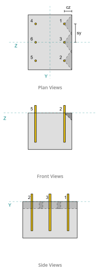
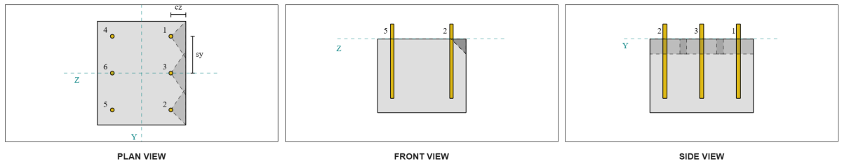
Dalla disposizione, Ancore 1 e 4 sono più vicini al bordo e hanno il la distanza ca1 più breve. Utilizzando questi valori ca1 per proiettare i coni di cedimento, il software ha identificato questi ancoraggi come ancore singole, poiché i loro coni proiettati non si sovrappongono. Si è inoltre stabilito che il supporto non fosse un membro ristretto, quindi la distanza ca1 viene utilizzata direttamente senza modifiche.
Ricordiamo che si assume che la forza di taglio sia distribuita tra tutti gli ancoraggi. Il calcolo per il Carico di taglio Vy applicato ad ogni singolo ancoraggio è:
\( V_{faperp} = frac{V_y}{n / a} = frac{2\,\testo{kip}}{6} = 0,33333,testo{kip} \)
Consideriamo Ancorare 1. L'area massima proiettata di un singolo ancoraggio viene calcolata utilizzando ACI 318-19 Eq. 17.7.2.1.3.
\( UN_{VCo} = 4.5 (c_{a1, s1})^2 = 4.5 \volte (2\,\testo{pollici})^2 = 18,testo{pollici}^ 2 \)
L'effettiva area proiettata viene quindi determinata dalla larghezza e dall'altezza del cono di rottura proiettato.
\( B_{Vc} = min(c_{sinistra,Sforzo in alto Rinforzo},\, 1.5c_{a1, s1}) + \min(c_{giusto,Sforzo in alto Rinforzo},\, 1.5c_{a1, s1}) \)
\( B_{Vc} = min(10\,\testo{pollici},\, 1.5 \volte 2,testo{pollici}) + \min(2\,\testo{pollici},\, 1.5 \volte 2,testo{pollici}) = 5,testo{pollici} \)
\( Per calcolarlo{Vc} = min(1.5c_{a1, s1},\, t_{conc}) = min(1.5 \volte 2,testo{pollici},\, 10\,\testo{pollici}) = 3,testo{pollici} \)
\( UN_{Vc} = B_{Vc} Per calcolarlo{Vc} = 5,testo{pollici} \volte 3,testo{pollici} = 15,testo{pollici}^ 2 \)
Il prossimo passo è usare Equazioni 17.7.2.2.1a e 17.7.2.2.1b per calcolare la resistenza allo sfondamento di base di un singolo ancoraggio. La capacità di governo è considerata il valore minore.
\( V_{b1} = 7 \sinistra( \frac{\min(l_e,\, 8d_a)}{d_a} \giusto)^{0.2} \sqrt{\frac{d_a}{\testo{pollici}}} \lambda_a sqrt{\frac{f'_c}{\testo{psi}}} \sinistra( \frac{c_{a1, s1}}{\testo{pollici}} \giusto)^{1.5} \,\testo{Trova la distribuzione delle sollecitazioni in una piastra quadrata a causa degli effetti di un foro circolare al centro sotto un carico lineare uniforme nel piano} \)
\( V_{b1} = 7 \volte sinistra( \frac{\min(8\,\testo{pollici},\, 8 \volte 0,5,testo{pollici})}{0.5\,\testo{pollici}} \giusto)^{0.2} \volte sqrt{\frac{0.5\,\testo{pollici}}{1\,\testo{pollici}}} \volte 1 \volte sqrt{\frac{3\,\testo{KSI}}{0.001\,\testo{KSI}}} \volte sinistra( \frac{2\,\testo{pollici}}{1\,\testo{pollici}} \giusto)^{1.5} \volte 0,001,testo{kip} \)
\( V_{b1} = 1.1623,testo{kip} \)
\( V_{b2} = 9 \lambda_a sqrt{\frac{f'_c}{\testo{psi}}} \sinistra( \frac{c_{a1, s1}}{\testo{pollici}} \giusto)^{1.5} \,\testo{Trova la distribuzione delle sollecitazioni in una piastra quadrata a causa degli effetti di un foro circolare al centro sotto un carico lineare uniforme nel piano} \)
\( V_{b2} = 9 \volte 1 \volte sqrt{\frac{3\,\testo{KSI}}{0.001\,\testo{KSI}}} \volte sinistra( \frac{2\,\testo{pollici}}{1\,\testo{pollici}} \giusto)^{1.5} \volte 0,001,testo{kip} = 1.3943,testo{kip} \)
\( V_b = min(V_{b1},\, V_{b2}) = min(1.1623\,\testo{kip},\, 1.3943\,\testo{kip}) = 1.1623,testo{kip} \)
Successivamente, il parametri della capacità di sblocco sono determinati. La fattore di effetto del bordo di breakout è calcolato secondo ACI 318-19 Clausola 17.7.2.4, che per il fattore di spessore è calcolato secondo Clausola 17.7.2.6.1.
\( \Psi_{ed,V } = minsinistra(1.0,\, 0.7 + 0.3 \sinistra( \frac{c_{a2,s1}}{1.5c_{a1, s1}} \giusto) \giusto) = minsinistra(1,\, 0.7 + 0.3 \volte sinistra( \frac{2\,\testo{pollici}}{1.5 \volte 2,testo{pollici}} \giusto) \giusto) = 0.9 \)
\( \Psi_{h,V } = massimosinistra( \sqrt{ \frac{1.5c_{a1, s1}}{t_{conc}} },\, 1.0 \giusto) = massimosinistra( \sqrt{ \frac{1.5 \volte 2,testo{pollici}}{10\,\testo{pollici}} },\, 1 \giusto) = 1 \)
Infine, ACI 318-19 Clausola 17.7.2.1(un carico) viene utilizzato per determinare la capacità di rottura del calcestruzzo di un singolo ancorante a taglio. La capacità calcolata per il taglio Vy nella direzione perpendicolare è 0.69 kips.
\( \phi V_{cbperp} = phi a sinistra( \frac{UN_{Vc}}{UN_{VCo}} \giusto) \Psi_{ed,V } \Psi_{c,V } \Psi_{h,V } V_b \)
\( \phi V_{cbperp} = 0.65 \volte sinistra( \frac{15\,\testo{pollici}^ 2}{18\,\testo{pollici}^ 2} \giusto) \volte 0.86 \volte 1 \volte 1 \volte 1.1623,testo{kip} = 0,56661,testo{kip} \)
La capacità calcolata per Vy taglio nel perpendicolare la direzione è 0.56 kips.
Capacità del bordo parallelo:
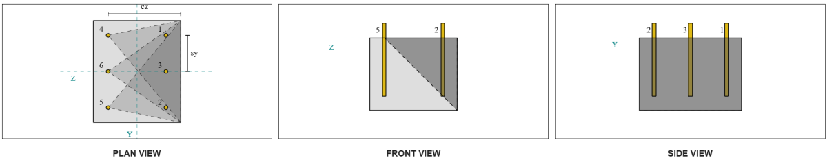
In questo scenario è possibile anche la rottura lungo il bordo parallelo al carico, quindi il capacità di strappo del calcestruzzo per il bordo parallelo deve essere determinato. Gli ancoraggi o il gruppo di ancoraggi considerati sono quelli allineati al bordo parallelo. conseguentemente, il ca1 la distanza dal bordo viene misurata dall'ancoraggio al bordo lungo la direzione Z. In base alla figura seguente, le proiezioni del cono di rottura si sovrappongono; perciò, le ancore vengono trattate come un gruppo.
Astuccio 1:
Astuccio 2:
Ci riferiamo a ACI 318-19 Figura. R17.7.2.1b per i diversi casi utilizzati nella valutazione dei gruppi di ancoraggio. In questo design della piastra di base, rondelle saldate vengono utilizzati specificatamente. Pertanto, solo Astuccio 2 è controllato.
Il carico richiesto per il gruppo di ancoraggio in Case 2 è considerato come il carico di taglio totale.
\( V_{faparallelo,caso2} = V_y = 2,testo{kip} \)
Nel calcolo della capacità della Cassa 2 fallimento, le ancore considerate sono le ancoraggi posteriori. Di conseguenza, la distanza dal bordo ca1 è misurata dal gruppo di ancoraggio posteriore al bordo di rottura.
Con questa distanza ca1 e orientamento del bordo, occorre verificare se il supporto si qualifica come membro ristretto. Seguente ACI 318-19 Clausola 17.7.2.1.2, il software SkyCiv Base Plate ha identificato il supporto come stretto. Pertanto, il distanza ca1 modificata si usa, che si calcola sia 6.667 pollici.
Si seguono gli stessi passaggi del caso perpendicolare: calcolando il aree di guasto previste, il resistenza alla rottura di base di un singolo ancoraggio, che per il parametri di sblocco. I valori calcolati per ogni passaggio sono mostrati di seguito.
\( UN_{VCo} = 4.5 (c_{'a1,g2})^2 = 4.5 \volte (6.6667\,\testo{pollici})^2 = 200,testo{pollici}^ 2 \)
\( UN_{Vc} = B_{Vc} Per calcolarlo{Vc} = 14,testo{pollici} \volte 10,testo{pollici} = 140,testo{pollici}^ 2 \)
\( V_{b1} = 7.0733,testo{kip} \)
\( V_{b2} = 8.4853,testo{kip} \)
\( V_b = min(V_{b1},\, V_{b2}) = min(7.0733\,\testo{kip},\, 8.4853\,\testo{kip}) = 7.0733,testo{kip} \)
\( \Psi_{ed,V } = 1.0 \)
\( \Psi_{h,V } = 1.0 \)
L'equazione per la capacità del bordo parallelo differisce dalla capacità del bordo perpendicolare. ACI 318-19 Clausola 17.7.2.1(c) viene applicato, dove si trova l'equazione di breakout moltiplicato per 2.
\( \phi V_{cbgparallelo} = 2 \phi sinistra( \frac{UN_{Vc}}{UN_{VCo}} \giusto) \Psi_{ed,V } \Psi_{c,V } \Psi_{h,V } V_b \)
\( \phi V_{cbgparallelo} = 2 \volte 0.65 \volte sinistra( \frac{140\,\testo{pollici}^ 2}{200\testo{pollici}^ 2} \giusto) \volte 1 \volte 1 \volte 1 \volte 7.0733,testo{kip} = 6.4367,testo{kip} \)
La capacità calcolata per Vy taglio nel parallelo la direzione è 6.43 kips.
Valutiamo ora separatamente i cedimenti perpendicolari e paralleli.
- Per la rottura del bordo perpendicolare, da 0.33 kip < 0.56 kip, la capacità di rottura a taglio del calcestruzzo di progetto è sufficiente.
- Per la rottura del bordo parallelo, da 2 kip < 6.43 kip, la capacità di rottura a taglio del calcestruzzo di progetto è sufficiente.
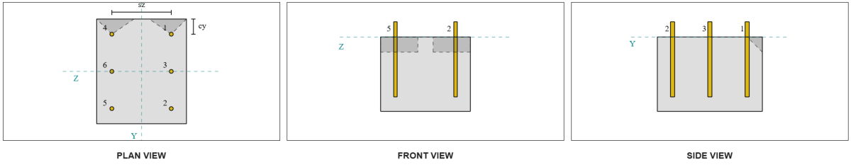
Dai un'occhiata #3: Calcola la capacità di breakout del calcestruzzo a causa del taglio VZ
Anche la piastra di base è sottoposta a Taglio Vz, occorre quindi verificare i bordi di rottura perpendicolari e paralleli al taglio Vz. Utilizzando lo stesso approccio, le capacità perpendicolari e parallele vengono calcolate come 2.45 kips e 1.26 kips, rispettivamente.
Bordo perpendicolare:
Bordo parallelo:
Queste capacità vengono poi confrontate con le forze richieste.
- Per la rottura del bordo perpendicolare, da 2 kip < 2.45 kip, la capacità di rottura a taglio del calcestruzzo è sufficiente.
- Per la rottura del bordo parallelo, da 0.33 kip < 1.26 kip, la capacità di rottura a taglio del calcestruzzo è sufficiente.
Dai un'occhiata #4: Calcola la capacità del cemento.
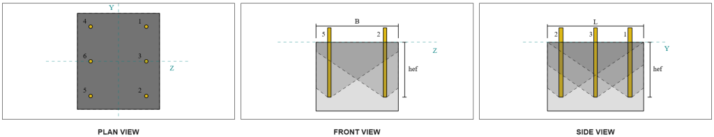
La cono di cemento per cedimento dello scalzamento è lo stesso cono utilizzato nella verifica di rottura a trazione. Per calcolare la capacità di scalzamento a taglio, dovrà essere preventivamente determinata la resistenza nominale alla rottura a trazione del singolo ancorante o del gruppo di ancoranti. I calcoli dettagliati per la verifica di rottura a trazione sono già trattati nel Esempi di progettazione SkyCiv per carico di tensione.
È importante notare che la determinazione del gruppo di ancoraggio per la rottura a taglio è diversa da quella per la rottura a taglio. Pertanto, gli ancoraggi nel progetto devono ancora essere controllati per determinare se sono atto avere un gruppo o come ancore singole contro il cedimento dello sfilamento a taglio. La classificazione del supporto come a sezione stretta deve essere verificato e deve seguire le stesse condizioni utilizzate per rottura della tensione.
Dai calcoli SkyCiv, il resistenza alla rottura a trazione nominale del gruppo di ancoraggio è 12.772 kips. Con un fattore di protezione pari a kcp=2, la capacità di estrazione del progetto è:
\( \phi V_{cpp} = hy k_{cp} N_{cbg} = 0.65 \volte 2 \volte 12.772 \,\testo{kip} = 16.604,testo{kip} \)
La forza richiesta è la risultante dei carichi di taglio applicati. Poiché tutte le ancore appartengono a un unico gruppo, il taglio risultante totale è assegnato al gruppo.
\( V_{Fare} = sqrt{(V_y)^ 2 + (V_Z)^ 2} = sqrt{(2\,\testo{kip})^ 2 + (2\,\testo{kip})^ 2} = 2.8284,testo{kip} \)
\( V_{Fare} = sinistra( \frac{V_{Fare}}{n / a} \giusto) N_{un carico,G1} = sinistra( \frac{2.8284\,\testo{kip}}{6} \giusto) \volte 6 = 2.8284,testo{kip} \)
Poiché il carico di taglio totale è inferiore alla capacità del gruppo di ancoraggio, 2.82 kips < 18.976 kips, la capacità di estrazione del progetto è sufficiente.
Dai un'occhiata #5: Calcola la capacità di taglio dell'asta di ancoraggio
Ricordiamolo in questo esempio di progettazione, il taglio è distribuito su tutti gli ancoraggi. Il carico di taglio totale per ancorante è quindi la risultante della sua quota del carico Vy e della sua quota del carico Vz..
\( v_{Fare,y} = frac{V_y}{n / a} = frac{2\,\testo{kip}}{6} = 0,33333,testo{kip} \)
\( v_{Fare,z} = frac{V_Z}{n / a} = frac{2\,\testo{kip}}{6} = 0,33333,testo{kip} \)
\( V_{Fare} = sqrt{(v_{Fare,y})^ 2 + (v_{Fare,z})^ 2} \)
\( V_{Fare} = sqrt{(0.33333\,\testo{kip})^ 2 + (0.33333\,\testo{kip})^ 2} = 0,4714,testo{kip} \)
Questo dà il sforzo di taglio sulla barra di ancoraggio come:
\( f_v = frac{V_{Fare}}{UN_{asta}} = frac{0.4714\,\testo{kip}}{0.19635\,\testo{pollici}^ 2} = 2.4008,testo{KSI} \)
Perché è presente una lavapiatti, un carico di taglio eccentrico viene indotto nella barra di ancoraggio. L'eccentricità viene considerata pari alla metà della distanza misurata dalla parte superiore del supporto in calcestruzzo al centro della rondella, tenendo conto dello spessore della piastra di base. Fare riferimento a Guida alla progettazione AISC 1, 3Sezione della terza edizione 4.3.3.
\( e = 0.5 \sinistra( \frac{t_{p.p}}{2} + t_{p.p} \giusto) = 0.5 \volte sinistra( \frac{0.25\,\testo{pollici}}{2} + 0.75\,\testo{pollici} \giusto) = 0,4375,testo{pollici} \)
Il momento derivante dal taglio eccentrico viene quindi espresso come an sollecitazione assiale nell'asta di ancoraggio. Utilizzando il modulo di sezione, la sollecitazione assiale dovuta a questo momento viene calcolata come:
\( Z_{asta} = frac{\pi}{32} (d_a)^3 = frac{\pi}{32} \volte (0.5\,\testo{pollici})^3 = 0,012272,testo{pollici}^ 3 \)
\( f_t = frac{V_{Fare} e}{Z_{asta}} = frac{0.4714\,\testo{kip} \volte 0,4375,testo{pollici}}{0.012272\,\testo{pollici}^ 3} = 16.806,testo{KSI} \)
Capacità di taglio della barra di ancoraggio ACI:
Seguente ACI 318-19 Clausola 17.7.1, viene quindi determinata la resistenza del progetto. A 0.8 fattore di riduzione viene applicato a causa della presenza di cuscinetti per malta. La capacità progettuale è quindi:
\( \phi V_{per,Qui} = 0.8 \phi 0.6 UN_{lo so,v} f_{uta} = 0.8 \volte 0.65 \volte 0.6 \volte 0,1419testo{pollici}^2 volte 90testo{KSI} = 3,9845testo{kip} \)
Come alternativa, il Software della piastra base SkyCiv consente il 0.8 semplificazione da disattivare, e utilizzare nei calcoli lo spessore effettivo del tampone di malta. In questo caso, l'eccentricità totale comprende il tampone di malta, e la resistenza combinata a taglio e assiale è determinata secondo le disposizioni AISC.
Capacità di taglio della barra di ancoraggio AISC:
Primo, il tensioni nominali di taglio e trazione sono determinati per un'asta A325.
\( F_{nv} = 0.45 F_{u,anc} = 0.45 \volte 120\ \testo{KSI} = 54\ \testo{KSI} \)
\( F_{nt} = 0.75 F_{u,anc} = 0.75 \volte 120\ \testo{KSI} = 90\ \testo{KSI} \)
Il metodo AISC utilizza AISC 360-22 Eq. J3-3a, che può essere espresso per includere gli effetti dello stress assiale. Questa operazione viene eseguita come segue.
\( F'_{nv} = min sinistra( 1.3 F_{nv} – \sinistra( \frac{F_{nv}}{\Phi f_{nt}} \giusto) f_t,\; F_{nv} \giusto) \)
\( F'_{nv} = min sinistra( 1.3 \volte 54\ \testo{KSI} – \sinistra( \frac{54\ \testo{KSI}}{0.75 \volte 90\ \testo{KSI}} \giusto) \volte 16.806\ \testo{KSI},\; 54\ \testo{KSI} \giusto) = 54\ \testo{KSI} \)
La capacità di taglio di progetto del metodo AISC viene quindi calcolata come:
\( \Phi R_{n,\matematica{aisc}} = phi F’_{nv} UN_{asta} = 0.75 \volte 54\ \testo{KSI} \volte 0.19635\ \testo{pollici}^2 = 7.9522\)
Per garantire che entrambi i metodi siano coperti, la capacità di governo è considerata la minore tra le due, che è 3.98 kip.
\( \phi V_n = min sinistra( \phi V_{per,Qui},\; \Phi R_{n,\matematica{aisc}} \giusto) = min (3.9845\ \testo{kip},\; 7.9522\ \testo{kip}) = 3.9845\ \testo{kip} \)
Poiché il carico di taglio per barra di ancoraggio è inferiore alla capacità di taglio della barra di ancoraggio, 0.47 kip < 3.98 kip, la capacità di taglio della barra di ancoraggio di progetto è sufficiente.
Riepilogo del progetto
La Software di progettazione della piastra di base Skyciv Può generare automaticamente un rapporto di calcolo passo-passo per questo esempio di progettazione. Fornisce inoltre un riepilogo dei controlli eseguiti e dei loro rapporti risultanti, rendere le informazioni facili da capire a colpo d'occhio. Di seguito è riportata una tabella di riepilogo del campione, che è incluso nel rapporto.
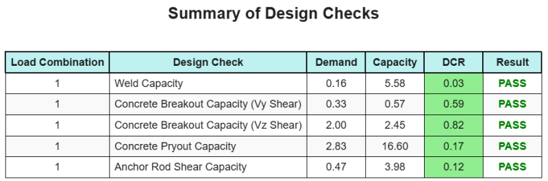
Rapporto campione Skyciv
Scopri il livello di dettaglio e chiarezza che puoi aspettarti da un rapporto sulla progettazione della piastra base SkyCiv. Il rapporto include tutti i controlli chiave della progettazione, equazioni, e i risultati presentati in un formato chiaro e di facile lettura. È pienamente conforme agli standard di progettazione. Fare clic di seguito per visualizzare un rapporto di esempio generato utilizzando il calcolatore della piastra di base SkyCiv.
Acquista software di base
Acquista da solo la versione completa del modulo di progettazione della piastra di base senza altri moduli SkyCiv. Questo ti dà un set completo di risultati per la progettazione della piastra di base, tra cui report dettagliati e più funzionalità.