In alcuni casi, Le sezioni non prismatiche o rastremate sono utilizzate negli elementi strutturali per ottenere una struttura a prestazioni migliori. L'idea alla base dei membri non prismatici è quella di fornire gradualmente meno materiale e quindi meno capacità nelle parti del membro in cui le forze interne sono più piccole, e più materiale nelle porzioni in cui le forze interne sono più grandi. In altre parole, Le sezioni affusolate cercano di seguire la distribuzione delle forze interne/sollecitazioni lungo il membro.
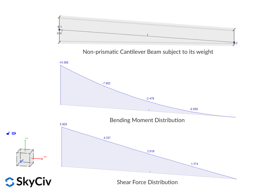
Per esempio, in un raggio a sbalzo soggetto al proprio peso, Il momento di flessione e la forza di taglio prendono i loro valori massimi all'estremità fissa e sono zero all'estremità libera, seguendo una distribuzione quadratica e lineare rispettivamente. In quel caso, L'estremità fissa del raggio richiede la massima capacità mentre la fine libera non ha alcuna domanda, Per questo motivo, Una sezione affusolata può aiutare a salvare il materiale e utilizzare in modo efficiente la capacità disponibile.
C'è un altro articolo che spiega in dettaglio come modellare sezioni e costi non prismatici o affusolati e come la variazione della sezione lineare è idealizzata con membri prismatici più brevi nella fase di analisi. In questo articolo, Ci concentreremo su come il modulo di progettazione membro Skyciv si occupa di sezioni non prismatiche quando si eseguono i controlli di progettazione. Al momento, Ci sono alcune sezioni non prismatiche pienamente supportate nel software:
- Scatole non prismatiche a freddo (sezioni cave rettangolari composte da due canali leccati) secondo AS/NZS 4600:2018
- Piastre saldate Trave a I non prismatica secondo AS 4100:2020 e NZS 3404:1997
In quei codici, esistono due diversi tipi di controlli che devono essere soddisfatti attraverso diversi stati limite: controlli di sezione e controlli di membri o segmenti. Prima di immergerci in ciascun gruppo di controlli, Esaminiamo rapidamente le informazioni disponibili sulle sezioni che provengono dalla fase di analisi.
Proprietà della sezione disponibili
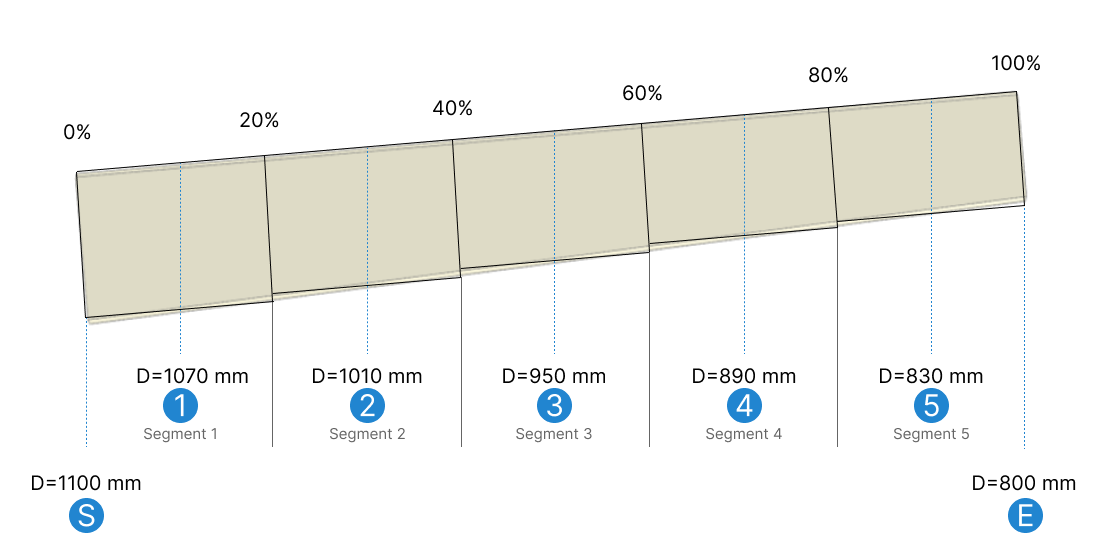
Supponendo che la sezione affusolata sia stata creata “media” dimensioni dei membri prismatici e 5 segmenti prismatici, ci sarà 7 stazioni (mostrato come linee tratteggiate blu nel diagramma sotto) con proprietà di sezione calcolate/conosciute, corrispondente alle sezioni che un membro non prismatico a variazione lineare avrebbe nel mezzo di ogni segmento prismatico. Questo è mostrato nell'immagine seguente etichettata come s (Avvia forma), 1, 2, 3, 4, 5, e E (forma di fine). Per l'esempio, Variamo la profondità della sezione da 1010 mm a 800 mm.
Controlli di sezione
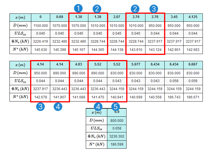
I controlli delle sezioni vengono eseguiti da stazione per stazione utilizzando la capacità della sezione nella stazione data e le forze interne che agiscono individualmente o combinate esattamente in quella posizione lungo il membro. Ogni stazione utilizzerà le proprietà della sezione del segmento prismatico a cui appartiene la stazione. Proprio ai segmenti prismatici’ variazione, Ci saranno due stazioni nella stessa posizione con una sezione diversa, Una stazione appartenente al segmento a sinistra della variazione e l'altra a destra della variazione:
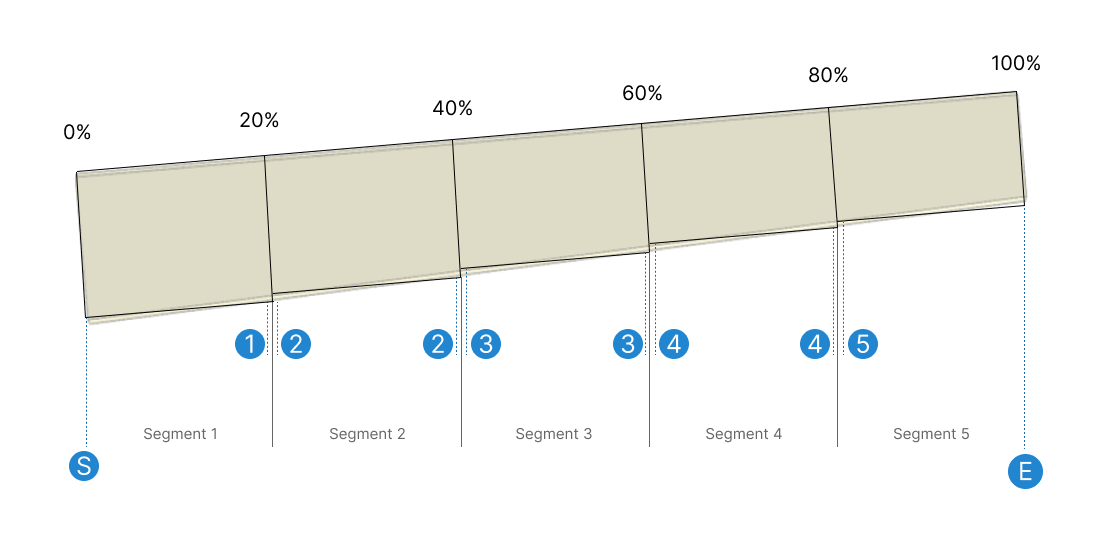
Questo è il motivo per cui nel rapporto di progettazione ci sono stazioni ripetute con due diversi valori di capacità, Ogni stazione utilizza una sezione diversa e può quindi produrre risultati diversi. Quindi le stazioni di controllo finali comprendono (un carico) i punti di valutazione dai risultati dell'analisi e (b) Il numero totale di stazioni più usando la logica sopra:
Controlli dei membri
Per i controlli di membro o segmento, I singoli segmenti sono definiti dalle restrizioni laterali specificate dall'utente. Queste restrizioni provengono da altri elementi in contatto con il membro del design, come Purlins e Fly-Braces che aiutano a prevenire la deformazione nel membro. Per i controlli dei membri, Le forze interne utilizzate sono i risultati massimi presenti all'interno del segmento, Non importa se si verificano in diverse posizioni lungo il membro. La sezione utilizzata per la capacità viene scelta dalle sezioni disponibili utilizzando uno dei seguenti criteri:
- Sezione critica: Sezione della stazione con il rapporto di utilità più alto dal controllo della sezione.
- Sezione minima: Sezione con l'area/capacità più bassa.
- Sezione di media lunghezza: Sezione più vicina alla metà geometrica del segmento.
Come esempio, Prendiamo un segmento che, a causa delle restrizioni laterali assegnate, corre dal centro del segmento 2 (30%), al centro del segmento 4 (70%) come mostrato nell'immagine qui sotto.
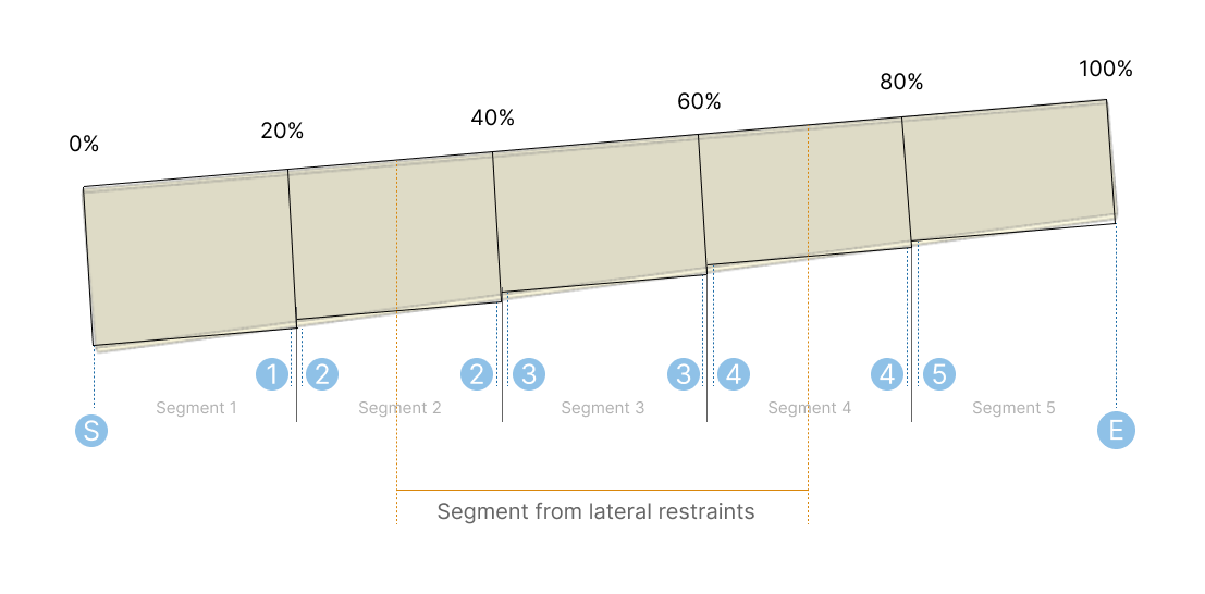
Supponendo che la stazione critica per quel segmento sia all'inizio del segmento (La metà del secondo segmento prismatico globale – 30% dell'intero membro), La sezione utilizzata per la capacità nel controllo dei membri sarà:
- Sezione critica: Sezione 2
- Sezione minima: Sezione 4
- Sezione di media lunghezza: Sezione 3, che è la sezione più vicina disponibile per 50% del segmento di restrizioni laterali (Medio del terzo segmento prismatico globale)