Disegno a pelo singolo secondo AS 2159 (2009) & 3600 (2018)
In caso di elevato carico laterale o condizioni del suolo sfavorevoli, la fondazione su pali è più preferita rispetto alle fondamenta poco profonde. Tentativi come metodi di modifica del suolo possono essere fatti per evitare cumuli, però, questi metodi possono comportare processi costosi, in cui questo caso, pile forse anche più economiche.
Il modulo SkyCiv Foundation Design include la progettazione di pali conformi all'American Concrete Institute (ACI 318) e standard australiani (AS 2159 & 3600).
SkyCiv di Esportare il rapporto di calcolo dettagliato da utilizzare come deliverable o in un pacchetto di calcolo semplifica l'applicazione di AS 2159 e 3600 verifiche nei progetti strutturali.
Vuoi provare il software Foundation Design di SkyCiv? Il nostro strumento gratuito consente agli utenti di eseguire calcoli di carico senza alcun download o installazione!
Progettare la forza geotecnica di un palo
I carichi verticali applicati sui pali sono portati dal supporto di estremità del palo e dalla pelle o dall'attrito dell'albero lungo la sua lunghezza. La forza geotecnica del progetto (Rd,g) è uguale alla massima resistenza geotecnica (Rd,e) moltiplicato per un fattore di riduzione geotecnico (øg) come specificato su AS 2159 Sezione 4.3.1.
\({R}_{d,g} = {ø}_{g} × {R}_{d,e}\) (1)
Rd,g = Progettare la forza geotecnica
Rd,e = Massima resistenza geotecnica
øg = Fattore di riduzione geotecnico
Massima forza geotecnica (Rd,e)
La resistenza geotecnica finale è uguale alla somma dell'attrito della pelle fattorizzato del pelo (fm,S ) moltiplicato per l'area della superficie laterale e la resistenza di base moltiplicata per l'area della sezione trasversale sulla punta del palo.
\( {R}_{d,e} = [{R}_{S} × ({f}_{m,S} × {A}_{S} )] + ({f}_{b} × {A}_{b} )\) (2)
RS = Fattore di riduzione per la resistenza dell'albero
fm,S = Resistenza all'attrito dell'albero
AS = Superficie laterale
fb = Termine di resistenza di base
Ab = Area della sezione trasversale sulla punta del palo
Per una guida più dettagliata, dai un'occhiata al nostro articolo sul calcolo la resistenza all'attrito della pelle e la capacità portante.
Fattore di riduzione geotecnico (øg)
Il fattore di riduzione geotecnico è un calcolo basato sul rischio per il progetto definitivo che tiene conto di diversi fattori, come le condizioni del sito, disegno del mucchio, e fattori di installazione. Il suo valore varia comunemente da 0.40 per 0.90. AS 2159 4.3.1 indica anche come stimare il suo valore come mostrato nell'equazione (3).
\( {ø}_{g} = {ø}_{gb} + [K × ({ø}_{tf} – {ø}_{gb})] ≥ {ø}_{gb} \) (3)
øgb = Fattore di riduzione della resistenza geotecnica di base
øtf = Fattore di prova intrinseco
K= Fattore di beneficio del test
Il test intrinseco e i fattori di beneficio del test dipendono entrambi dal tipo di test di carico utilizzato sui pali. I loro valori sono specificati nella tabella 1 e sulle equazioni (4) e (5). Il test del carico su pali è discusso brevemente nella Sezione 8 di AS 2159.
| Fattore di prova intrinseco (øtf) | |||||||||||||
|---|---|---|---|---|---|---|---|---|---|---|---|---|---|
| Prova di carico statico | 0.90 | ||||||||||||
| Prove di carico rapide | 0.75 | ||||||||||||
| Prove di carico dinamico di pali preformati | 0.80 | ||||||||||||
| Prove di carico dinamico di pali non preformati | 0.75 | ||||||||||||
| Prova di carico bidirezionale | 0.85 | ||||||||||||
| Nessun test | 0.80 | ||||||||||||
tavolo 1: Valori del fattore di prova intrinseco
Fattore di vantaggio del test per il test di carico statico:
\( K = frac{1.33 × pag}{p + 3.3} ≤ 1\) (4)
Fattore di vantaggio del test per il test di carico dinamico:
\( K = frac{1.13 × pag}{p + 3.3} ≤ 1\) (5)
p = Percentuale del totale delle pile che vengono testate e soddisfano i criteri di accettazione
Il fattore di riduzione della resistenza geotecnica di base viene valutato utilizzando una procedura di valutazione del rischio discussa nella sezione 4.3. di AS 2159. L'esito di tale procedura è l'Individual Risk Rating (IRR) e un disegno complessivo di valutazione media del rischio (ARR) che deve essere utilizzato per determinare il valore di øgb come mostrato nella tabella 2.
| Fattore di riduzione della forza geotecnica di base (øgb) | |||||||||||||
|---|---|---|---|---|---|---|---|---|---|---|---|---|---|
| Valutazione del rischio medio (ARR) | Categoria di rischio | øgb per sistemi a bassa ridondanza | øgb per sistemi ad alta ridondanza | ||||||||||
| AR ≤ 1.5 | Molto basso | 0.67 | 0.76 | ||||||||||
| 1.5 < AR ≤ 2.0 | Da molto basso a basso | 0.61 | 0.70 | ||||||||||
| 2.0 < AR ≤ 2.5 | Basso | 0.56 | 0.64 | ||||||||||
| 2.5 < AR ≤ 3.0 | Da basso a moderato | 0.52 | 0.60 | ||||||||||
| 3.0 < AR ≤ 3.5 | Moderare | 0.48 | 0.56 | ||||||||||
| 3.5 < AR ≤ 4.0 | Da moderato ad alto | 0.45 | 0.53 | ||||||||||
| 4.0 < AR ≤ 4.5 | Alto | 0.42 | 0.50 | ||||||||||
| ARR > 4.5 | Molto alto | 0.40 | 0.47 | ||||||||||
tavolo 2: Valori per il fattore di riduzione geotecnico di base, (AS 2159 tavolo 4.3.2)
I sistemi a bassa ridondanza sono pile singole pesantemente caricate mentre i sistemi ad alta ridondanza includono grandi gruppi di pile sotto grandi pile o gruppi di pile con più di 4 emorroidi.
Progettare la forza strutturale
Le pile sono strutturalmente progettate quasi come una colonna. Progettare la resistenza strutturale (Rd,S) richiede capacità ultime, come forze assiali e di taglio, e momento flettente. La resistenza strutturale di progetto di un palo di cemento è equivalente alla resistenza di progetto finale (Rnoi) ridotto di un fattore di riduzione della forza (øS) e un fattore di posizionamento concreto (K), come dichiarato dalla Sezione 5.2.1 di AS 2159.
\( {R}_{d,S} = {ø}_{S} × k × {R}_{noi} \) (6)
øS = Fattore di riduzione della forza
k = Fattore di posa del calcestruzzo
Rnoi = Massima forza progettuale
I valori per il fattore di riduzione della resistenza sono riportati in tabella 3. Il fattore di posizionamento concreto varia da 0.75 per 1.0, a seconda del metodo di costruzione della pila. Tuttavia, per pali diversi da calcestruzzo e boiacca, k deve essere preso come 1.0.
| Fattori di riduzione della forza (ø) | |||||||||||||
|---|---|---|---|---|---|---|---|---|---|---|---|---|---|
| Forza assiale senza flessione | 0.65 | ||||||||||||
| Flessione senza forza assiale (øpb) | 0.65 ≤ 1.24 – [(13 × kuo)/12] ≤ 0.85 | ||||||||||||
| Piegatura con compressione assiale: | |||||||||||||
| (io) Nu ≥ Nub | 0.60 | ||||||||||||
| (ii) Nu < Nub | 0.60 + {(øpb – 0.66) × [1 – (Nu/Nub)]} | ||||||||||||
| cesoia | 0.70 | ||||||||||||
tavolo 3: Fattori di riduzione della forza (tavolo 2.2.2, AS 3600-18)
Capacità assiali e flessionali di un unico palo
Simile alle colonne, i pali possono anche essere soggetti a compressione combinata e carico flettente. Le capacità assiali e flessionali vengono verificate mediante un diagramma di interazione. Questo diagramma è una rappresentazione visiva del comportamento delle capacità flessionali e assiali causate da un aumento del carico dal punto di flessione puro fino al raggiungimento di un punto di equilibrio.
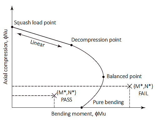
figura 1: Diagramma di interazione delle colonne
Carico di zucca (Nuo)
Il punto di carico dello squash è un punto del diagramma in cui la pila si romperà in pura compressione. A questo punto, il carico assiale viene applicato sul baricentro plastico della sezione per rimanere in compressione senza piegarsi. Carico di zucca (Nuo) e la posizione del baricentro plastico (dq) sono calcolati come mostrato nelle equazioni (7) & (8). Sebbene la posizione del baricentro di plastica possa essere presa come 1/2 della profondità totale della sezione per sezioni simmetriche con disposizione di armatura simmetrica.
\( {N}_{uo} = ø × [({A}_{g} – {A}_{S}) × ({un'}_{1} × f'c) + ({A}_{S} × {f}_{il suo})] \) (7)
Ag = Area della sezione trasversale lorda
AS = Superficie totale dell'acciaio
un'1 = 1.0 – (0.003 × f'c) [0.72 ≤α1 ≤0,85]
f'c = Resistenza del calcestruzzo
fil suo = Resistenza allo snervamento dell'acciaio
\( {d}_{q} = Frac{[(b × D) – {A}_{S}] × ({un'}_{1} × f'c) × somma_{io=1}^{n} ({A}_{bi} × {f}_{il suo} × {d}_{fare})}{{N}_{uo}} \) (8)
b = Larghezza della sezione trasversale del palo
D = Profondità o diametro della sezione del palo
Abi = Area della barra d'armatura considerata
dfare = Si considera la profondità della barra d'armatura
Squash punto di carico fino al punto di decompressione
Il punto di decompressione è dove è uguale la deformazione del calcestruzzo alla fibra di compressione estrema 0.003 e la deformazione nella fibra a trazione estrema è zero. La resistenza del palo tra il carico di schiacciamento ed i punti di decompressione può essere calcolata mediante interpolazione lineare con fattore di riduzione della resistenza (øS) di 0.6.
Punto di decompressione fino alla pura flessione
Il punto di flessione puro è dove la capacità di carico assiale è zero. Il passaggio dal punto di decompressione alla flessione pura utilizza un fattore di riduzione della forza di 0.6 per 0.8 e un parametro di input (Ku) è introdotto. Il valore di ku inizia a 1 al punto di decompressione e diminuisce fino a raggiungere la flessione pura. Tra il passaggio dei due punti, si raggiunge una condizione equilibrata. A questo punto, la deformazione del calcestruzzo è al suo limite (ec=0,003) e la deformazione esterna dell'acciaio raggiunge la resa (eS=0,0025), Il valore di ku a questo punto è approssimativamente 0.54 con un fattore di riduzione della forza di 0.6.
Una volta un valore di ku è selezionato, possono essere calcolate le forze di trazione e di compressione della sezione. Il carico assiale sulla sezione è equivalente alla somma delle forze di trazione e di compressione, mentre il momento flettente viene calcolato risolvendo queste forze attorno all'asse neutro. Di seguito sono elencati i calcoli per le forze di compressione e di trazione
Forza dovuta al cemento (Fcc):
\( {F}_{cc} = {un'}_{2} × f'c × {A}_{c} \) (9)
un'2 = 0.85 – (0.0015 × f'c) [un'2 ≥0.67]
Ac = Area del blocco di compressione (fare riferimento alla figura 2)
= b × c × ku × d (sezione rettangolare)
=(1/2) × (θ – sinθ) × (D/2)2 (sezione circolare)
γ = 0.97 – (0.0025 × f'c) [c ≥0.67]
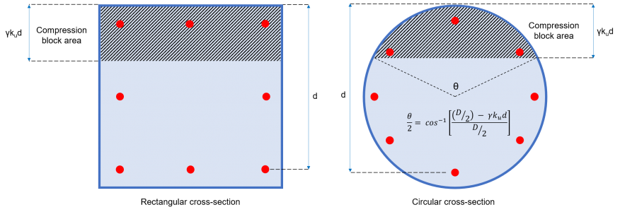
figura 2: Area del blocco di compressione del calcestruzzo
Forza (Fe) e momento (Mio) contributo di ogni singolo bar:
Ciascuna barra d'armatura della sezione esercita una forza che può essere di compressione o di trazione, a seconda della deformazione della barra del valore (ee) mostrato nell'equazione (10).
\( {e}_{e} = frac{{e}_{c}}{({K}_{u} × d)} × [({K}_{u} × d) – {d}_{fare}] \) (10)
dfare = Profondità della barra considerata
ec= Deformazione del calcestruzzo = 0.003
Se ee < 0 (la barra è in tensione)
Se ee > 0 (la barra è in compressione)
Barra in compressione:
\( {F}_{e} = {σ}_{e} × {A}_{bi} \) (11)
σe = Sollecitazione in barra = Minimo [(ee × ES ), fil suo]
ES = Modulo elastico dell'acciaio
Abi = Zona bar
Barra in tensione:
\( {F}_{e} = [{σ}_{e} – ({un'}_{2} × f'c)] × {A}_{bi} ≥ 0\) (12)
σe = Sollecitazione in barra = Minimo [(ee × ES ), –fil suo]
ES = Modulo elastico dell'acciaio
Abi = Zona bar
Momento per ogni barra:
\( {M}_{io} = {F}_{e} × {d}_{fare} \) (13)
Portata assiale del palo:
\( {l'isola}_{u} = ø × [ {F}_{cc} + {Σ}_{io=1}^{n} {F}_{e}]\) (14)
Capacità flessionale del palo:
\( {dolorante}_{u} = ø × [ ({N}_{u} × {d}_{q}) – ({F}_{cc} × {y}_{c}) – {Σ}_{io=1}^{n} {M}_{io}] \) (15)
Momento flettente di progetto:
Sezione 7.2 specifica che le pile devono avere una tolleranza di fuori posizione di 75 mm per il posizionamento orizzontale delle pile. Questo requisito può indurre un momento flettente pari al carico assiale moltiplicato per l'eccentricità di 75 mm. Inoltre, deve essere considerato anche un momento minimo di progetto equivalente alla forza assiale moltiplicata per 5% della larghezza minima complessiva della pila. Pertanto, il momento flettente di progetto dovrebbe essere il valore maggiore tra le equazioni 16a e 16b.
\( {M}_{d} = {{M}^{*}}_{applicato} + ({N}^{*} × 0.075 m) \) (16un carico)
\( {M}_{d} = {N}^{*} × (0.05 Un palo di cemento lungo 12 metri con un diametro di) \) (16b)
Md = Momento flettente di progetto
M*applicato = Momento applicato
N* = Carico assiale
D = Larghezza pila
Capacità di taglio di un singolo palo
Il calcolo della resistenza al taglio deve essere conforme alla Sezione 8.2 di AS 3600. La resistenza al taglio è equivalente a una capacità di taglio combinata del calcestruzzo e dell'armatura in acciaio (equazione 17).
\( {øV}_{u} = ø × ({V }_{uc} + {V }_{noi}) ≤ {øV}_{u,max} \) (17)
Resistenza al taglio del calcestruzzo (V uc)
Il contributo del calcestruzzo alla capacità di taglio viene calcolato come mostrato nell'equazione (18) che è definito nella sezione 8.2.4.1 di AS 3600. Questa sezione richiede anche che il valore di √f'c non debba essere superiore 9.0 MPa. I valori per il parametro kv e θv sono determinati utilizzando un metodo semplificato suggerito dall'art 8.2.4.3 di AS 3600.
\( {V }_{uc} = {K}_{v} × b × {d}_{v} × sqrt{f'c} \) (18)
dv = Profondità di taglio effettiva = Le sezioni rastremate sono attualmente supportate nei seguenti tipi di sezione [(0.72 Un palo di cemento lungo 12 metri con un diametro di ), (0.90 × d )]
Determinazione dell'area minima dell'armatura a taglio (Asv.min) & Kv:
L'area dell'armatura a taglio (Asv) è l'area totale della barra di tutte le barre d'acciaio fornite legate nella stessa direzione del carico applicato. Sezione 8.2.1.7 di AS 3600 fornito l'equazione per le armature a taglio trasversale minimo, che sarà:
\( \frac{{A}_{sv.min}}{S} = frac{0.08 × sqrt{f'c} × b}{{f}_{e f}} \)
fe f = Resistenza allo snervamento delle barre d'armatura a taglio
s= Spaziatura da centro a centro delle barre d'armatura a taglio
Per (Asv/S) < (Asv.min/S):
\( {K}_{v} = frac{200}{[1000 + (1.3 × {d}_{v} )]} ≤ 0.10\)
Per (Asv/S) ≥ (Asv.min/S):
\( {K}_{v} = 0.15 \)
Resistenza al taglio delle barre d'acciaio (V noi)
Il contributo delle armature a taglio trasversale alla capacità di taglio calcolata è mostrato nell'equazione (19), che è definito nella Sezione 8.2.5 di AS 3600.
\( {V }_{noi} = frac{{A}_{sv} × {f}_{e f} × {d}_{v}}{S} × lettino{θ}_{v} \) (19)
θv= angolo di inclinazione del puntone di compressione = 36º
Massima resistenza al taglio (V u.max)
La capacità di taglio è limitata e in nessun caso deve superare il valore massimo specificato nella Sezione 8.2.6 di AS 3600 (equazione 20).
\( {V }_{u.max} = 0.55 × [ (f'c × b × {d}_{v}) × frac{culla{θ}_{v} + culla{un'}_{v}}{1 + lettino^{2}{θ}_{v} }] \) (20)
un'v= angolo tra l'armatura a taglio inclinato e l'armatura a trazione longitudinale≈ 90º
Massima resistenza al taglio (V u)
La resistenza al taglio totale apportata dal calcestruzzo e dalle armature a taglio deve essere inferiore o uguale al valore limite di Vu.max
\( {V }_{u} = ({V }_{uc} + {V }_{noi} ) ≤ {V }_{u.max} \) (21)
Resistenza al taglio di progetto (øVu)
Il fattore di riduzione della capacità che deve essere applicato per la resistenza a taglio ultima è ø = 0.7. Pertanto, la resistenza al taglio di progetto del palo è data da:
\( {øV}_{u} = ø × ({V }_{uc} + {V }_{noi} ) \) (22)
Riferimenti
- Pacchetto, Lonnie (2018). Guida australiana per ingegneri strutturali. CRC Press.
- Progettazione e installazione di palificazioni (2009). AS 2159. Standard australiano
- Strutture in cemento (2018). AS 3600. Standard australiano