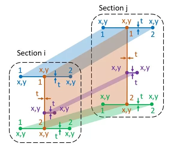
Ogni membro ha una sezione iniziale i e una sezione finale j. Una sezione è costituita da linee definite da due nodi, x,y nel piano della sezione. Ciascuna linea possiede uno spessore distinto t e appartiene a uno specifico gruppo di materiali. Il punto di riferimento per x,Le coordinate y possono essere scelte arbitrariamente nello spazio per ciascuna sezione. Il numero di righe in ciascuna sezione deve essere coerente. I dati per la tabella possono essere inseriti manualmente o importati da un foglio Excel. Inoltre, le forme delle sezioni possono essere importate da un file DXF memorizzato sul PC dell'utente.
Aggiorna t: Lo spessore comune può essere modificato per il gruppo selezionato di linee
Aggiorna mat.: Il gruppo di materiali comune può essere modificato per il gruppo di linee selezionato
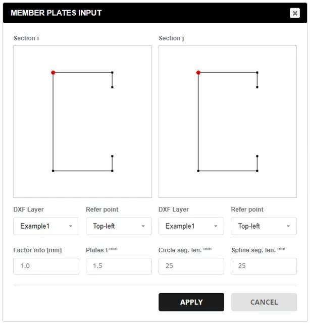
Dati da DXF.: Seleziona un file DXF dal tuo PC. Scegli il livello desiderato per gli elementi della sezione. Il punto di riferimento determina l'origine del x,y coordinate. Utilizzare il fattore per scalare le coordinate della sezione in millimetri. A tutte le linee verrà applicato uno spessore predefinito, che potrà essere modificato successivamente. Le entità DXF supportate includono: Linee, Polilinee, Archi, e Spline. Per archi e spline, la divisione del segmento è specificata per corrispondere alla dimensione della mesh preferita.
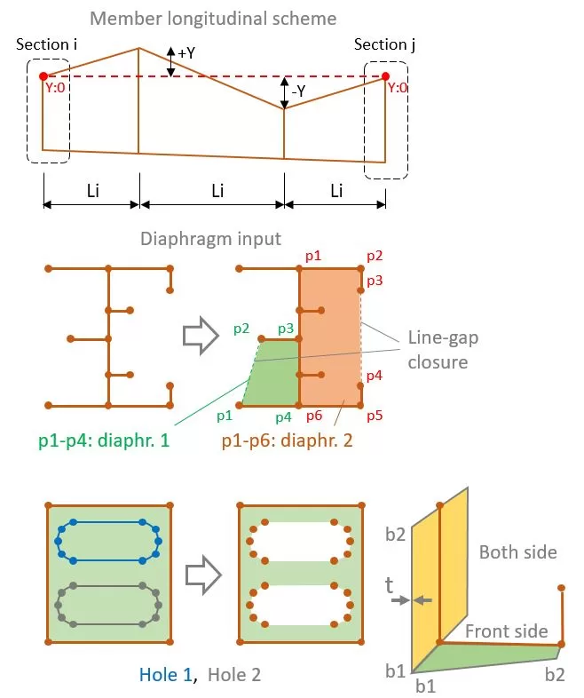
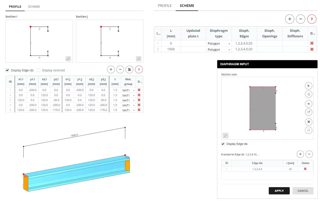
L'intero membro può essere rappresentato da una singola lunghezza L o da una serie di segmenti Li. Indipendentemente dal numero di segmenti, le linee di sezione iniziale e finale avranno le stesse coordinate definite nella scheda PROFILO. Ciascuna sezione può anche avere una posizione Y diversa.
Per ogni segmento dove L non è uguale a 0, lo spessore di un gruppo di piastre può essere aggiornato nella colonna "Piatto t aggiornato". è un punto fisso nello spazio che non si muove 0 per nascondere la targa e un valore maggiore di 0 per modificare lo spessore (t).
Per sezioni di segmento, è possibile aggiungere un diaframma se l'opzione "Poligono".’ viene scelto il tipo. Per specificare uno o più diaframmi, seleziona le linee che compongono la forma. È consentita una sola chiusura del gap di linea per formare la forma.
I fori possono anche essere incorporati all'interno del diaframma. Per fare questo, definire le forme dei fori selezionando le linee corrispondenti che racchiudono i fori.
Se viene specificato un diaframma, quindi è possibile definire anche flange o irrigidimenti selezionando le linee associate. Ogni flangia o irrigidimento ha una larghezza iniziale e finale (b1,b2), spessore t, e gruppo materiale.
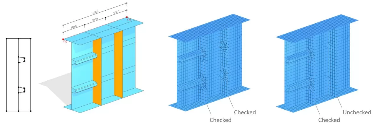
Esempio
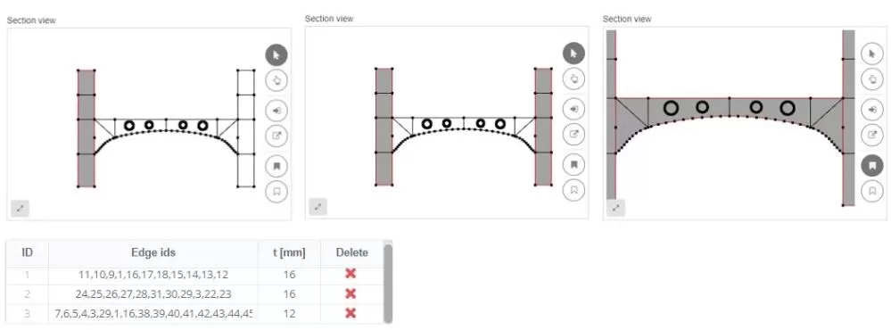
Quando si sistemano i bordi all'interno di un diaframma, possono essere presi in considerazione nel modello di mesh. Ad esempio, può verificarsi una situazione in cui un irrigidimento longitudinale è collegato a uno verticale. In tali scenari, i ‘bordi interni’’ l'opzione dovrebbe essere attivata. Tuttavia, se l'irrigidimento verticale non è collegato a nulla, questa opzione può essere disattivata.