Cosa significano le fissità dell'asta e come vengono identificate in 3D strutturale
Le fissità dell'estremità del membro controllano il modo in cui i membri sono collegati tra loro o ai nodi finali e includono condizioni come un fisso, appuntato, o collegamento a molla.
I codici di fissazione del membro accettano "F’ (Fisso), 'R’ (Rilasciato) e 'S’ (Primavera) valori. Questo codice si riferisce alla connessione dell'estremità del membro al suo nodo finale per ciascuno dei 6 gradi di libertà nel seguente ordine:
- Traslazione locale dell'asse x
- Traslazione locale dell'asse y
- Traslazione locale dell'asse z
- Rotazione locale dell'asse x
- Rotazione locale dell'asse Y
- Rotazione locale dell'asse z
NOTA: Le fissità di fine membro sono rispetto a quelle del membro sistema di assi locali piuttosto che il sistema di assi globale.
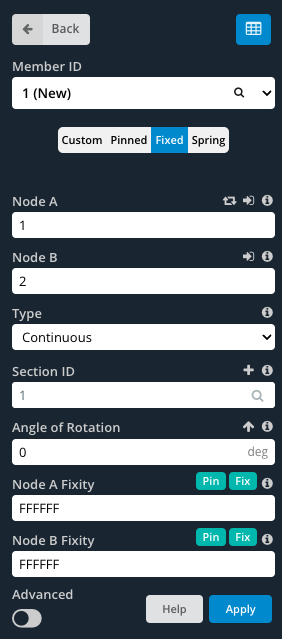
Fisso i membri hanno un valore completamente fisso, connessione rigida specificata da un codice di fissaggio "FFFFFF".
Appuntato i membri hanno una connessione a cerniera indicata da un codice "FFFFRR".
Primavera i membri hanno una connessione semirigida che consente una flessibilità parziale indicata da un codice "FFFFSS".
Per specificare valori personalizzati, assicurarsi che il costume è selezionato il pulsante. Ciò consente di modificare i campi di fissità finale.
Come individuare la fissità dell'estremità dell'elemento mentre si guarda nello spazio modello
Quando si modella con i membri, è conveniente conoscere i membri’ terminare la fissità senza dover fare clic su ciascun membro individualmente. Per impostazione predefinita, quando i membri vengono modellati, hanno fissità finali completamente fisse (FFFFFF). Il membro appare come una singola linea tra i nodi:

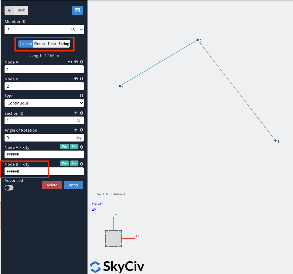
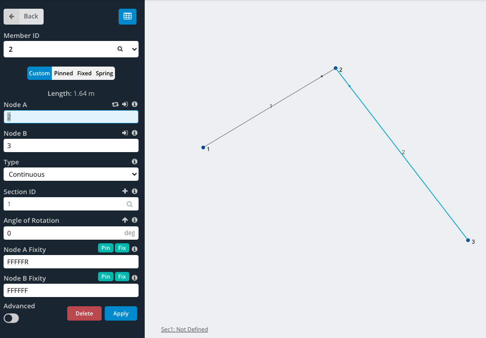
Quando uno qualsiasi dei gradi di libertà viene rilasciato, il membro avrà un piccolo punto vicino alla fine del membro (come mostrato sotto cerchiato in rosso). Per esempio, per i membri con fissaggi alle estremità fissate (FFFRRR), il membro sarebbe simile a questo:

Ulteriori spiegazioni
Per ulteriori informazioni sulle fissità dei membri, SkyCiv ha un articolo tecnico (compreso un video) nel nostro blog, CREDIAMO IN UN SOFTWARE MIGLIORE come modellare le fissità dei membri:
Esempio: Come modellare collegamenti a perni o cerniere
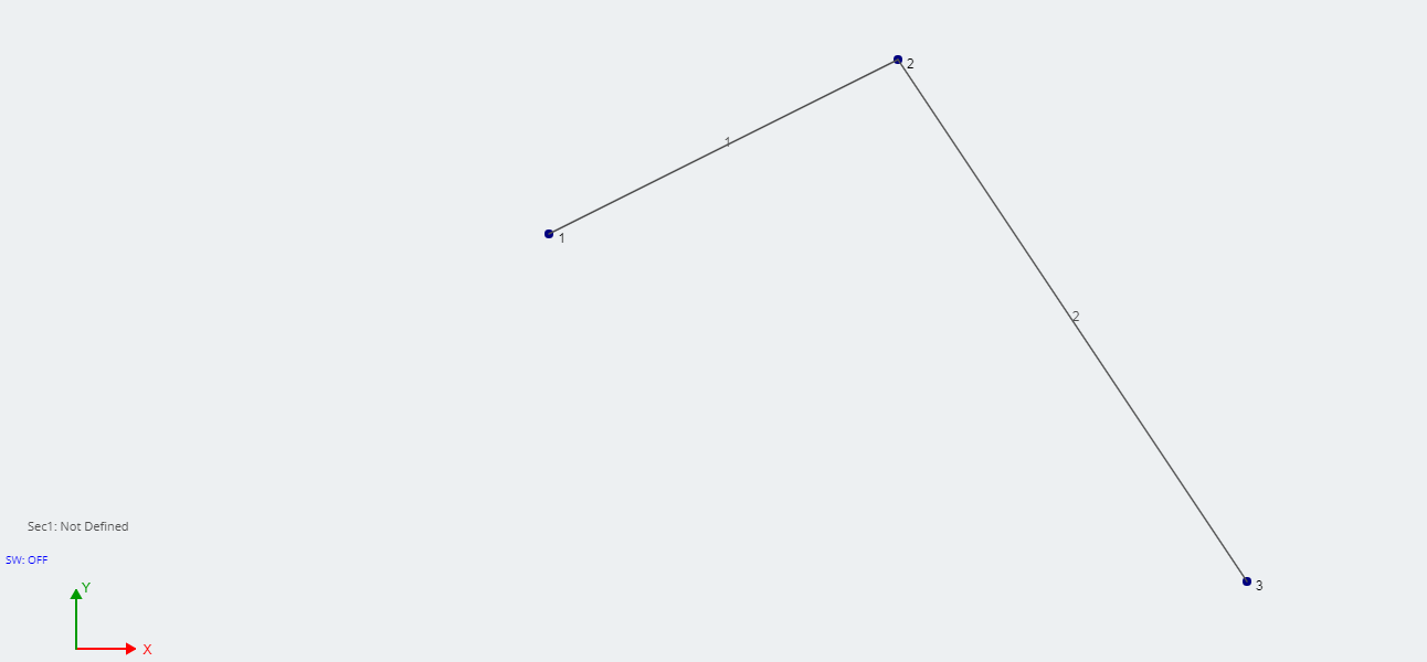
In questo esempio, creeremo una semplice connessione pin, come una cerniera. Inizia creando 3 nodi e unendoli con 2 aste. In questo esempio node, 2 sarà il cardine.
Maggiori informazioni
Per maggiori informazioni, SkyCiv ha un'ulteriore spiegazione su come modellare una cerniera, utilizzando il software di analisi strutturale.
video: Spiegazione dei gradi di libertà e dei codici di fissità