Lo scopo di questo articolo è illustrare come il Fondazione SkyCiv può essere utilizzata è stato preso il caso peggiore per ciascuna fondazione. Ciò comprende: calcolare la capacità del livello di servizio per sopportare la pressione, stabilità della base, dimensione del basamento; e il livello di resistenza per lo spessore e il rinforzo della fondazione. Sebbene il vero progetto menzionato in questo articolo contenga elementi in acciaio, ci concentreremo solo sulla progettazione delle fondamenta.
Sfondo del progetto
Questo progetto in primo piano è stato progettato e realizzato da BetaQuad Costruzione e Servizi Co., e si trova nel centro di Luzon, Filippine. Viene utilizzato per la produzione commerciale di cemento, avente una capacità produttiva giornaliera di 30,000 tonnellate metriche. L'impronta complessiva del progetto durante la costruzione è stata di circa 800 m2. Visto sotto, la parte in acciaio della struttura funge da telaio resistente al carico laterale (3F con soppalco). In tutto questo progetto ha 43 basamenti isolati necessari per la progettazione strutturale.
La base del codice di progettazione applicata per la progettazione della Fondazione era NSCP 2015. NSCP 2015 è simile all'ACI 318-14 codice , quale ACI 318-14 è disponibile sul nostro modulo di progettazione della Fondazione SkyCiv.
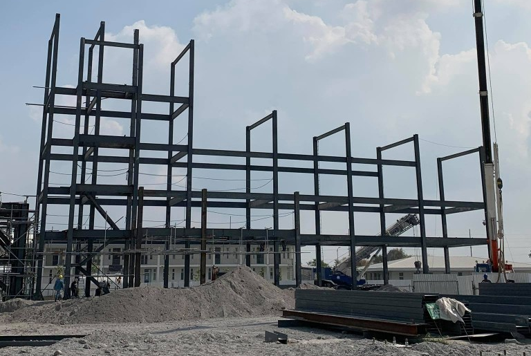
figura 1 : Foto in loco del progetto durante la costruzione
Modello e parametri SkyCiv
Modellare la struttura di cui sopra nel SkyCiv Structural 3D piattaforma significa che i progettisti hanno potuto sfruttare la vari strumenti di modellazione che sono disponibili per tutti gli utenti SkyCiv.
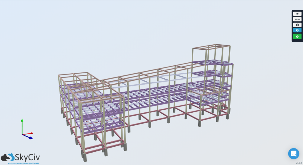
figura 2 : 3D Rendering del modello 3D strutturale SkyCiv
Ciò include il calcolo dell'SLS e dell'ULS
Per una progettazione del basamento, i parametri costruttivi più importanti necessari per la progettazione di fondazioni isolate sarebbero le caratteristiche sismiche del sito, e le proprietà del materiale del basamento. Per la posizione di questo progetto nel centro di Luzon, Filippine, la zona sismica corrispondente è Zona Sismica 4.
Ciò include il calcolo dell'SLS e dell'ULS, 20.68 MPa Ciò include il calcolo dell'SLS e dell'ULS 415 MPa Ciò include il calcolo dell'SLS e dell'ULS. Ciò include il calcolo dell'SLS e dell'ULS, Ciò include il calcolo dell'SLS e dell'ULS, Ciò include il calcolo dell'SLS e dell'ULS, Ciò include il calcolo dell'SLS e dell'ULS.
Ciò include il calcolo dell'SLS e dell'ULS
Ciò include il calcolo dell'SLS e dell'ULS, che delineano le proprietà del suolo e le caratteristiche complessive del sito. che delineano le proprietà del suolo e le caratteristiche complessive del sito, che delineano le proprietà del suolo e le caratteristiche complessive del sito:
che delineano le proprietà del suolo e le caratteristiche complessive del sito 2 metri
Capacità portante del suolo = 192 ACI-Verifica-Libri-Anteprima.
che delineano le proprietà del suolo e le caratteristiche complessive del sito 16 kN / m3
che delineano le proprietà del suolo e le caratteristiche complessive del sito, che delineano le proprietà del suolo e le caratteristiche complessive del sito.
Combinazioni di carico
Il modulo di progettazione della Fondazione SkyCiv può eseguire le combinazioni di carico di base e sono rappresentati come carichi di servizio e fattorizzati. Anche, il modulo di progettazione prenderà automaticamente in considerazione i parametri sismici durante i carichi sismici (E) avere qualsiasi valore nell'input.
Per la progettazione geotecnica (Livello di servizio):
Le combinazioni di carico applicabili per la progettazione geotecnica, che sono applicabili per entrambi gli ASCE 7-10 e NSCP 2015 codici di progettazione, sono i seguenti:
[1] D + L
[2] D + L + E/1.4
[3] D + E/1.4
Per la progettazione strutturale (Livello fattorizzato):
Le combinazioni di carico dell'applicazione per la progettazione strutturale applicabili per entrambi gli ASCE 7-10 e NSCP 2015 i codici di progettazione sono i seguenti:
[1] 1.4D
[2] 1.2D + 1.6L
[3] 1.2D + 1.0E + 1.0L
[4] 0.9D + 1.0E
Combinazione di carico SkyCiv
Combinazione di carico SkyCiv, Combinazione di carico SkyCiv.
Combinazione di carico SkyCiv & Reazioni
Combinazione di carico SkyCiv, le reazioni della colonna di base per ogni fondazione devono essere annotate nella parte di analisi di Structural 3D in modo che possano essere inserite nel modulo di progettazione della fondazione. Queste reazioni sono state determinate da un'analisi strutturale. Queste reazioni sono state determinate da un'analisi strutturale, è stato preso il caso peggiore per ciascuna fondazione. è stato preso il caso peggiore per ciascuna fondazione.
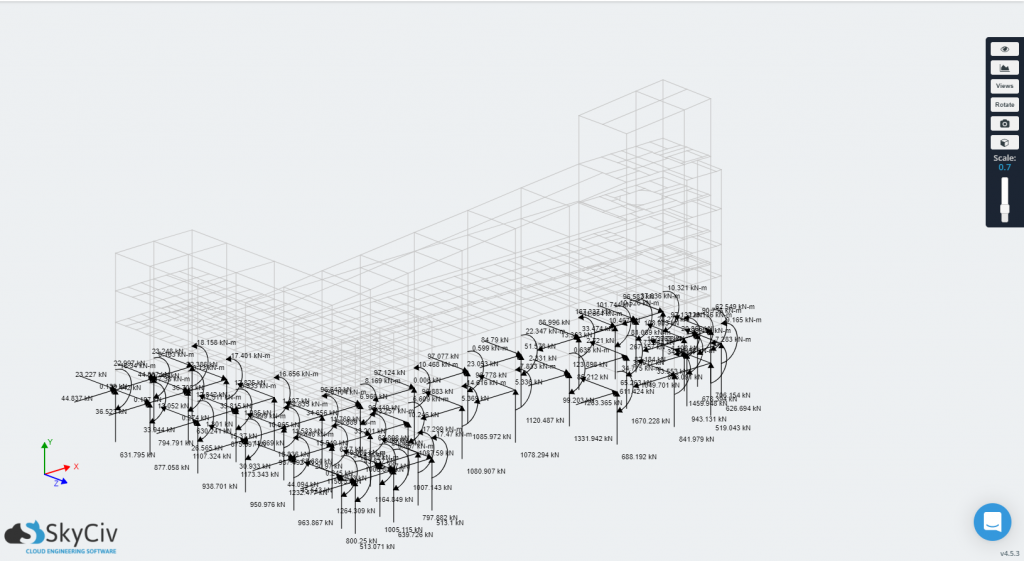
Figura 3-a: Reazioni alla base della colonna dal modello 3D strutturale
Nel Figura 3-a, S3D presenta i carichi di reazione che possono essere estratti e importati nel modulo di progettazione SkyCiv Foundation.
Ingresso & Output del modulo Foundation
Con le forze registrate, il modulo SkyCiv Foundation può essere utilizzato per analizzare e verificare i progetti di questi basamenti. Il modulo consente agli ingegneri di aggiungere tutte le fondazioni necessarie per il progetto. Quindi in questo caso, gli ingegneri hanno progettato e controllato il 43 basamenti in modo indipendente. Figura 3-b mostra l'interfaccia utente e la presentazione quando viene presa in considerazione più di una base per la progettazione.
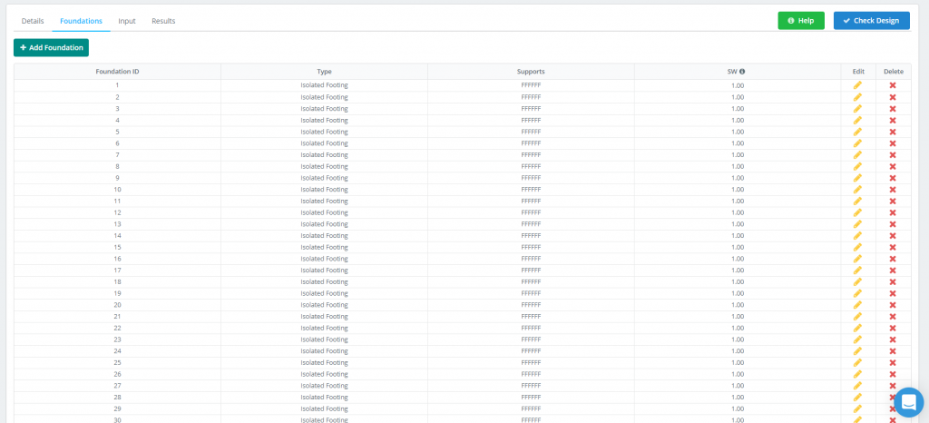
Figura 3-b: Scheda Progettazione della fondazione
Andare avanti, ogni progetto di fondazione incorpora un facile da usare, flusso di lavoro lineare, dove è possibile inserire tutte le informazioni registrate dai passaggi precedenti.
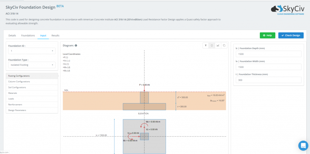
Figura 3-c: Interfaccia utente del modulo di progettazione delle fondazioni
Una volta stabiliti i requisiti di progettazione e immesse le proprietà e i carichi del materiale, il basamento è pronto per la progettazione. La presentazione dei risultati del progetto dopo aver fatto clic su Controlla il design il pulsante può essere visto in Figura 3-d. Questi risultati sono facilmente comprensibili, poiché sono presentati come rapporti unitari. Questi rapporti presentano l'Esperienza/Capacità per ogni singolo stato limite. Quando si scopre che è finita 1.0, il Stato del basamento diventerà rosso e verrà visualizzato “Fallire”. Altrimenti, quella cella sarà verde e mostrerà “Passaggio”. Ciò semplifica il controllo rapido di quali fondazioni potrebbero richiedere modifiche o ulteriore lavoro nel processo di progettazione.

Figura 3-d: Risultati della progettazione di esempio
Come indicato in Figura 3-d, i cinque diversi stati limite che vengono controllati in fase di progettazione sono:
- Dimensioni del basamento
- Stabilità come ribaltamento e scorrimento
- Taglio unidirezionale
- Taglio bidirezionale
- Flessione
Approfondire i rapporti unitari di ciascuno stato limite, gli ingegneri possono visualizzare i rapporti di progettazione della fondazione, accessibili per ciascuna fondazione. Questi rapporti aprono la scatola nera del software di ingegneria strutturale fornendo diagrammi e calcoli manuali dettagliati insieme in un PDF professionale che può essere esportato e utilizzato per l'uso nel progetto. Vedere Figure 3-e di seguito per vedere come appare uno di questi rapporti:
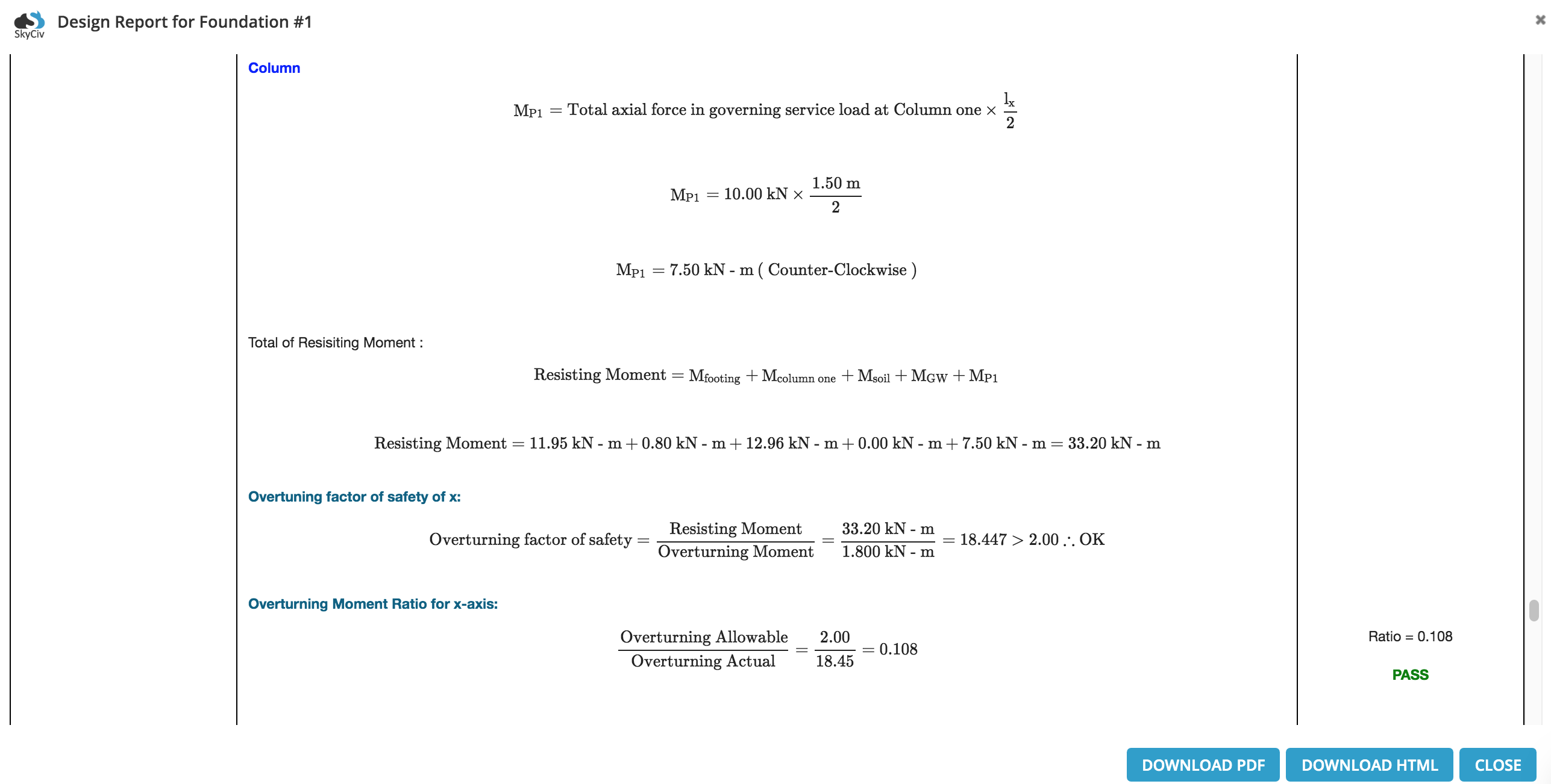
Figure 3-e: Esempio estratto da un rapporto dettagliato sulla progettazione della fondazione

Albert Pamonag, la linea d'azione del carico applicato
Ingegnere strutturale, Sviluppo del prodotto