
A column splice joins one column to the one above it. Columns arrive in mill lengths, and a building taller than that length needs its columns spliced, usually a few feet above floor level where the erector can reach the joint from the deck. Splices also turn up in retrofit work, where a column is extended, replaced or reinforced after a change in loading.
The splice has to carry whatever the column carries across the joint: axial compression, axial tension where uplift or overturning governs, cesoia, e momento. AISC 360-16 sets out the procedures for each. This page walks through designing one in SkyCiv Connection Design.
I calcoli dietro le connessioni di giunzione delle colonne
A column splice is a slow connection to calculate by hand. Each plate has to be checked in tension, compression and bearing, each bolt group in shear, and the whole joint for block shear, all of it doubled because the upper and lower columns are separate connections either side of the splice. AISC 360-16 gives the procedure for the axial, shear and moment capacity of each of those pieces.
La column splice calculator runs the same procedure. You supply the column sections, dimensioni della piastra, bolt specifications and loads, and it returns every check with its utilization ratio and the clause it came from, so the arithmetic stops being the part of the job that takes the time.
Bullonatura o saldatura: Scegliere il giusto metodo di connessione
Bolting is the usual choice for a column splice. A bolted splice is made in the air by an erector with a wrench, it tolerates the small misalignments that come with erecting a frame, and it can be slackened and adjusted if something does not line up. Welding a splice at height means preheat, position welding and inspection on a joint that is hard to reach.
Preparazione della superficie di contatto della colonna: La “Adatta per sopportare” Approccio
Where the column ends are prepared so the two sections sit in full contact, compression transfers through bearing rather than through the bolts. That usually means fewer bolts and thinner plates, because the plates only have to carry tension, taglio e momento.
It is a decision that has to reach the fabricator. Fit to bear is a preparation requirement on the shop drawings, not something the connection design can assume on its own, so if you design on that basis, say so on the drawing.
La necessità di connessioni di giunzione delle colonne
Splices appear wherever a column cannot be a single piece: buildings taller than the available mill length, sections that would be impossible to ship or lift in one, and retrofits where a column is extended or strengthened. In each case the splice has to reproduce the continuity the column would have had without it.
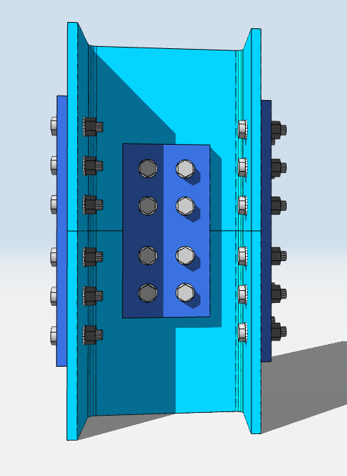
Designing a Column Splice in SkyCiv
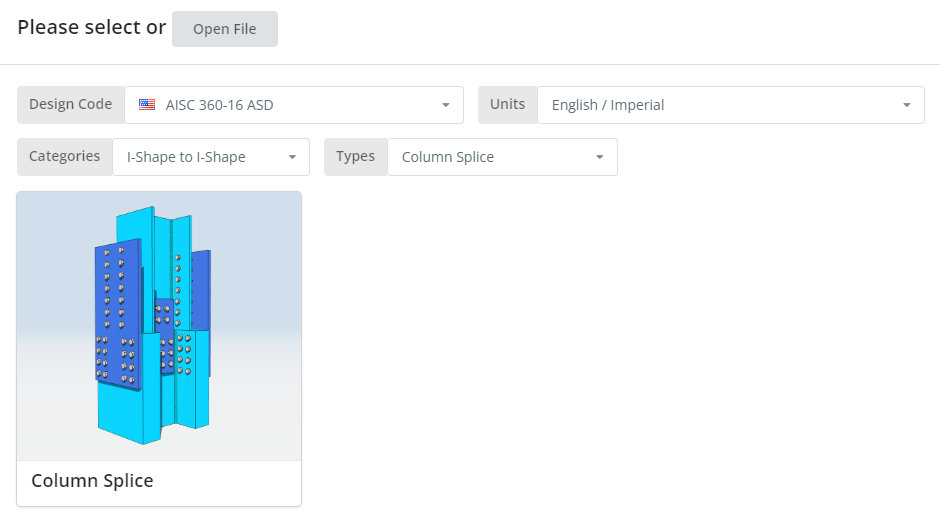
Il codice di progettazione può essere AISC 360-16 ASD o LRFD, e unità inglesi/imperiali o SI/metriche. Clicca il “Giunzione di colonna” piastrella.
Scheda Dettagli
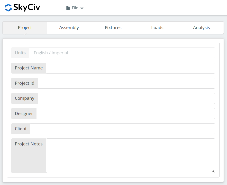
Registra qui i dettagli del progetto. Niente di tutto ciò cambia i calcoli, ma riporta nel rapporto, which is what makes a set of designs traceable later.
Scheda assemblaggio
Tre schede si trovano sotto Assemblaggio: the Lower Column, the Upper Column, e la connessione, which holds the flange plate and web plate.
Scheda della colonna inferiore
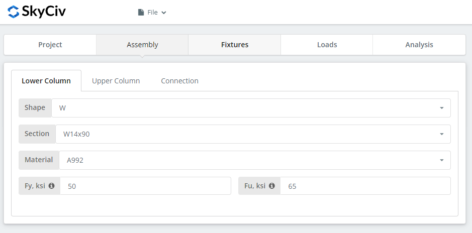
Specify the section and material grade of the lower column. A992 e A36 sono nell'elenco; per qualsiasi altra cosa scegli Personalizzato e inserisci Fy e Fu.
Scheda della colonna superiore
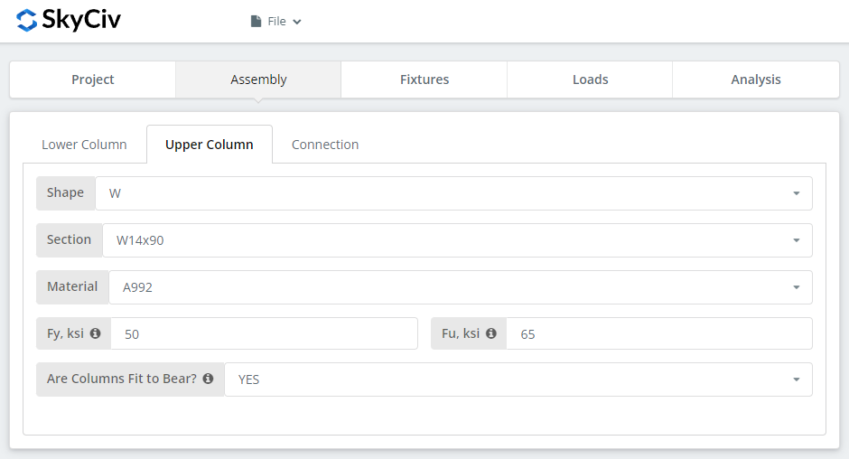
The same inputs, plus the option to declare the columns fit to bear. Selezionare “SÌ” and the compressive load is designed at the column contact surface instead of through the bolted connection, which gives a more economical connection. Come sopra, that is a requirement you have to pass to the fabricator: the columns must actually be prepared to bear.
Scheda Connessione: Flangia Piastra
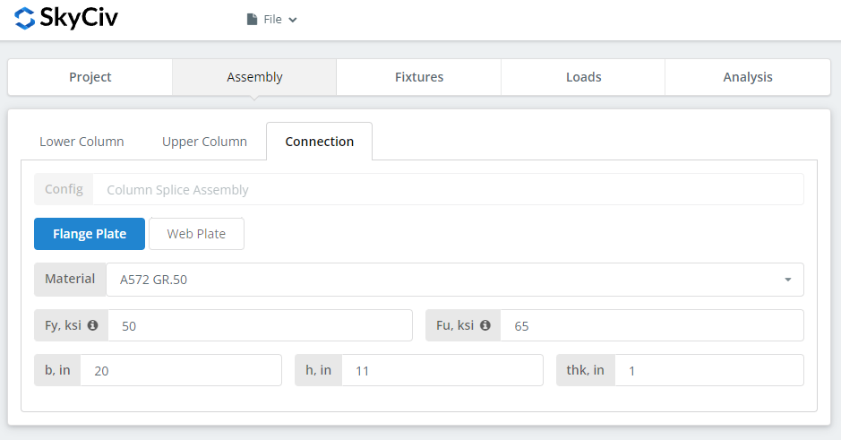
Set the flange plate properties: grade A36, A992 or A572 Gr.50, o Personalizzato con il tuo Fy e Fu, then b (larghezza), h (altezza) e thk (spessore). Watch the 3D renderer as you type and check the plate geometry makes sense, in particular that there is room for the bolt group you are about to define on the Fixtures tab.
Scheda Connessione: Piastra Web
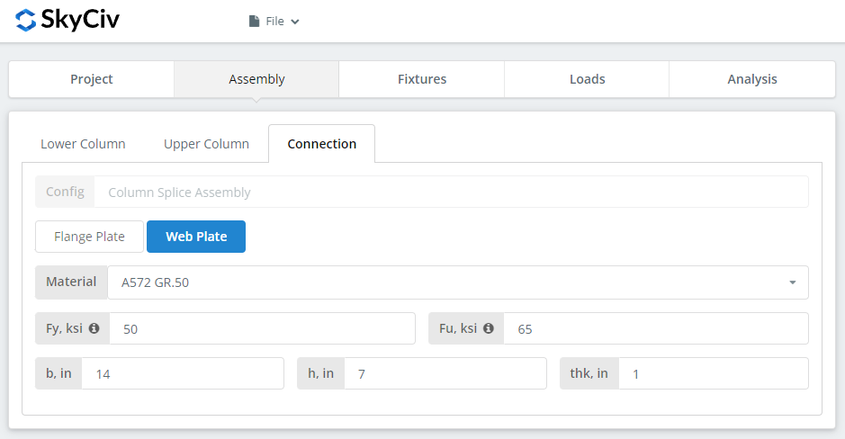
Same inputs as the flange plate. Check the renderer again before moving on.
Infisso 1-4 Scheda
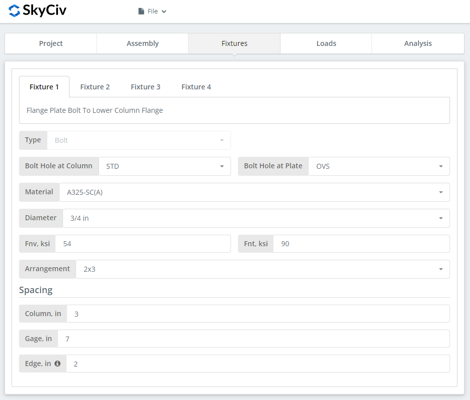
This is where the bolts are defined, one fixture per interface:
Infisso 1 – Piastra flangiata sulla flangia della colonna inferiore
Infisso 2 – Piastra flangiata sulla flangia della colonna superiore
Infisso 3 – Dalla piastra dell'anima all'anima della colonna inferiore
Infisso 4 – Dalla piastra dell'anima all'anima della colonna superiore
Primo, the bolt-hole types at the column flange or web and at the plates. I produttori di solito richiedono fori standard (malattie sessualmente trasmissibili) in the member and oversized holes (OVS) nel piatto, che acquista la tolleranza adeguata sul campo.
Successivamente, il materiale o la qualità del bullone: A307, A325, A490 o personalizzato. A325 e A490 sono gradi all'interno di ASTM F3125, che ha consolidato le vecchie specifiche autonome, so a drawing calling for A325 is calling for F3125 Grade A325. Scegliere N o X per una connessione di tipo cuscinetto e SC per una connessione critica allo scorrimento.
I giunti critici per lo scivolamento hanno una capacità di progettazione dei bulloni inferiore rispetto al tipo con cuscinetti, quindi usali dove lo scivolamento conta davvero: fori maggiorati o asolati, inversione di carico, o stanchezza. In questo esempio, using OVS holes in either the column or the plate means the bolts are automatically checked as slip-critical. Tra N e X, X indica la maggiore capacità di taglio del bullone, ma i fili devono essere esclusi dal piano di taglio, which the erector has to know about. Tra SC(A) e SC(B), SC(B) offre una capacità maggiore e richiede una superficie di contatto preparata in modo più accurato, ad esempio la sabbiatura commerciale SSPC-SP6.
Quindi il diametro del bullone, dal 5/8″ a 1-1/2″ o gli equivalenti metrici, e la disposizione, fino a 8 file di bulloni e 12 colonne a bullone. Set the bolt row spacing, column spacing and gage. La “bordo” input is the distance from the column end to the first bolt column.
For more on the fastener side of this, vedere la documentazione su bulloni.
Scheda Carichi
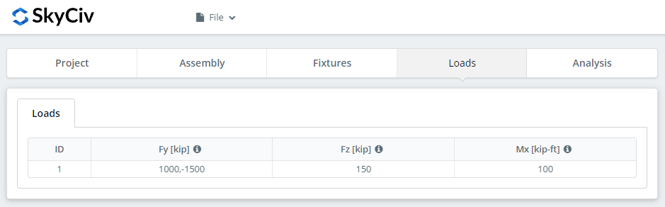
Enter the compressive or tensile load as ‘Fy’, the horizontal shear as ‘Fz’, and the strong axis moment as ‘Mx’. Hover the tooltips for the sign convention and direction of each.
Match the loads to the design method you picked at the start. LRFD prende in considerazione i carichi fattorizzati rispetto alla resistenza di progetto; L'ASD sopporta i carichi di servizio rispetto alla resistenza ammissibile. Il software non è in grado di riconoscere cosa hai digitato, so mixing them produces a utilization ratio that means nothing.
Scheda Risultati
Clic “Esegui controlli di progettazione”. Tutto ciò che manca nelle schede precedenti viene contrassegnato qui anziché essere impostato automaticamente come predefinito.
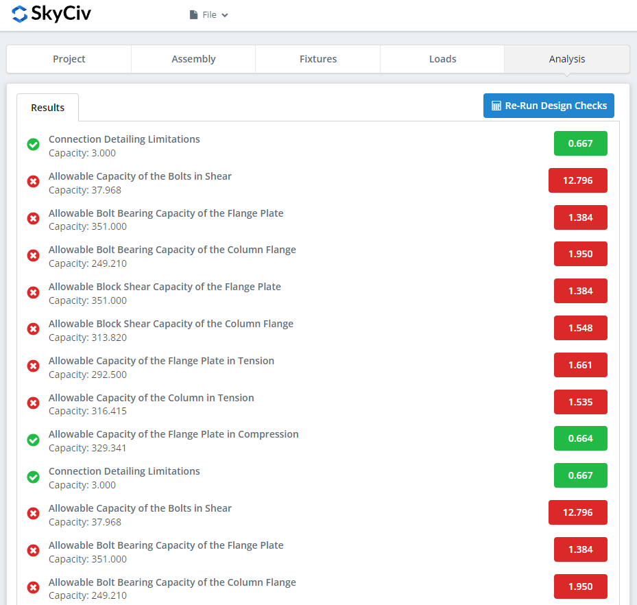
Il riepilogo mostra se la connessione è riuscita, with a utilization ratio against each check and the governing one called out. Se ha fallito, modificare gli input nelle schede precedenti e fare clic “Rieseguire i controlli di progettazione”. Quando passa, “Visualizza il rapporto di calcolo” apre il rapporto dettagliato.
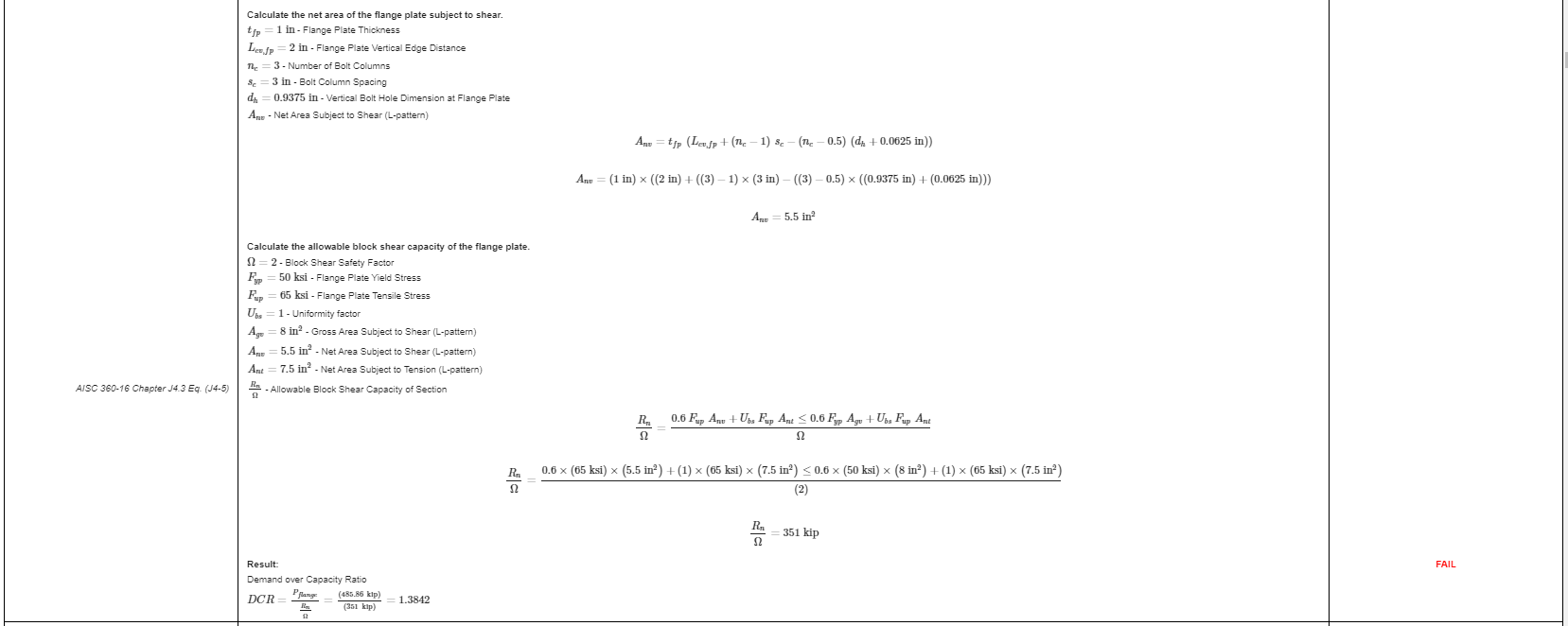
Questo è un estratto del rapporto. Ogni controllo riporta il riferimento al manuale o alla specifica AISC, and the working is laid out the way the specification lays it out, so a reviewing engineer can follow it line by line instead of reverse-engineering a result.
QuiÈ una copia PDF della relazione di calcolo dettagliata completa.
Designing a beam splice instead? La beam splice calculator works the same way.
Provalo tu stesso
The link below opens the module with the column splice already loaded. Enter your sections, piatti, bolts and loads, and every check and code reference is shown in full. Funziona nel browser, senza niente da installare.
