SkyCiv Foundation fornisce un'interfaccia intuitiva abbinata a un design potente per modellare facilmente fondazioni isolate. Nella versione recentemente rilasciata 3.1, l'interfaccia utente di Isolated Foundation è suddivisa in 2 contenitori, la sinistra contenente 4 schede che includono Dettagli, Fondamenti, Ingresso e risultati, e il diritto contenente il 3renderer D.
I. Dettagli
Una volta che l'utente ha scelto un codice di progettazione, l'utente può aggiornare i dettagli del progetto sul “Dettagli” scheda come mostrato di seguito. Le unità verranno impostate automaticamente in base al codice di progettazione scelto.
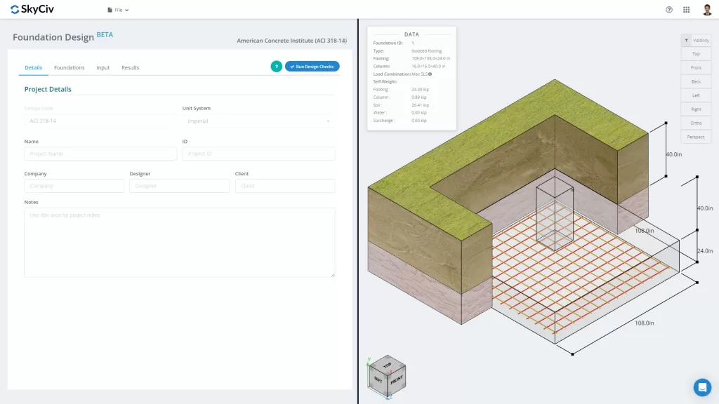
figura 1. Scheda Dettagli progetto
L'utente può compilare le informazioni per i dettagli del progetto, tra cui
- Un nome di progetto
- Un ID progetto
- Il nome della tua azienda
- Il disegnatore
- Il cliente
- Note di progetto (note aperte)
Tutte le informazioni verranno inserite nel rapporto di progettazione generato.
II. Fondamenti
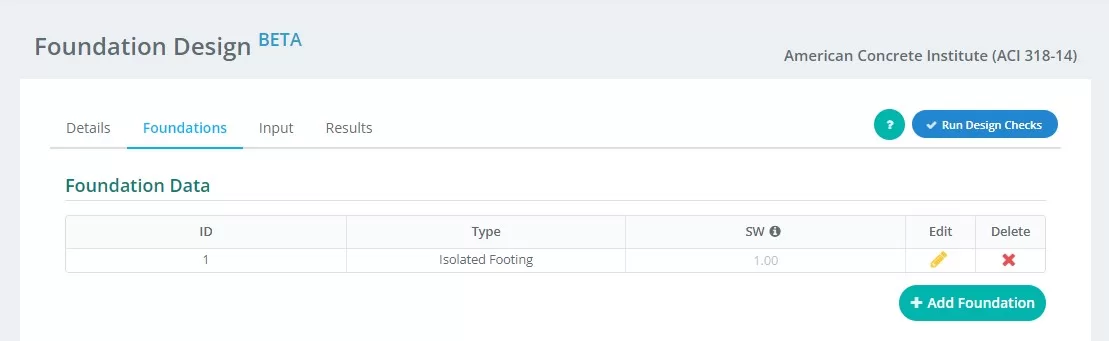
figura 2. Dettagli della scheda Base
Sintesi degli input sul “Fondazione” tab:
- ID Fondazione – assegnare l'identificazione numerica a ciascuna fondazione.
- genere – dovresti sentirti pronto per affrontare progetti molto più grandi e complessi “Fondazione isolata” dal menu a tendina.
- SW – fattore di peso proprio
- modificare – fai clic qui per iniziare a inserire i dati e modificare la tua base
- Eliminare – per eliminare la fondazione
III. Ingresso
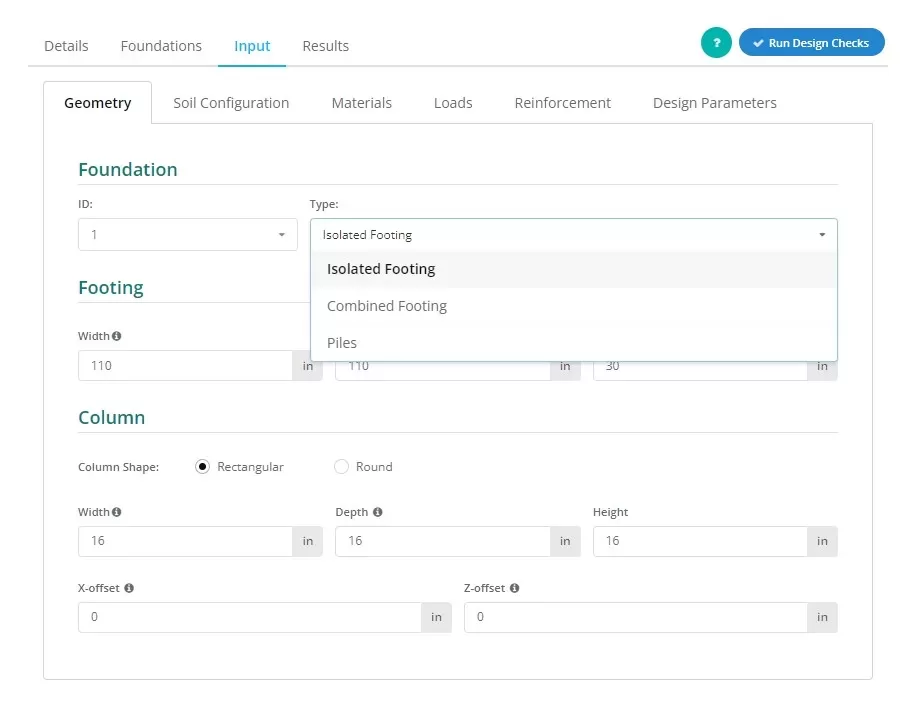
figura 3. Selezionando il Base isolata nel menu a tendina.
Gli utenti possono stabilire il tipo di fondazione come mostrato in figura 3, dovresti sentirti pronto per affrontare progetti molto più grandi e complessi “Base isolata” per far emergere questo punto di vista.
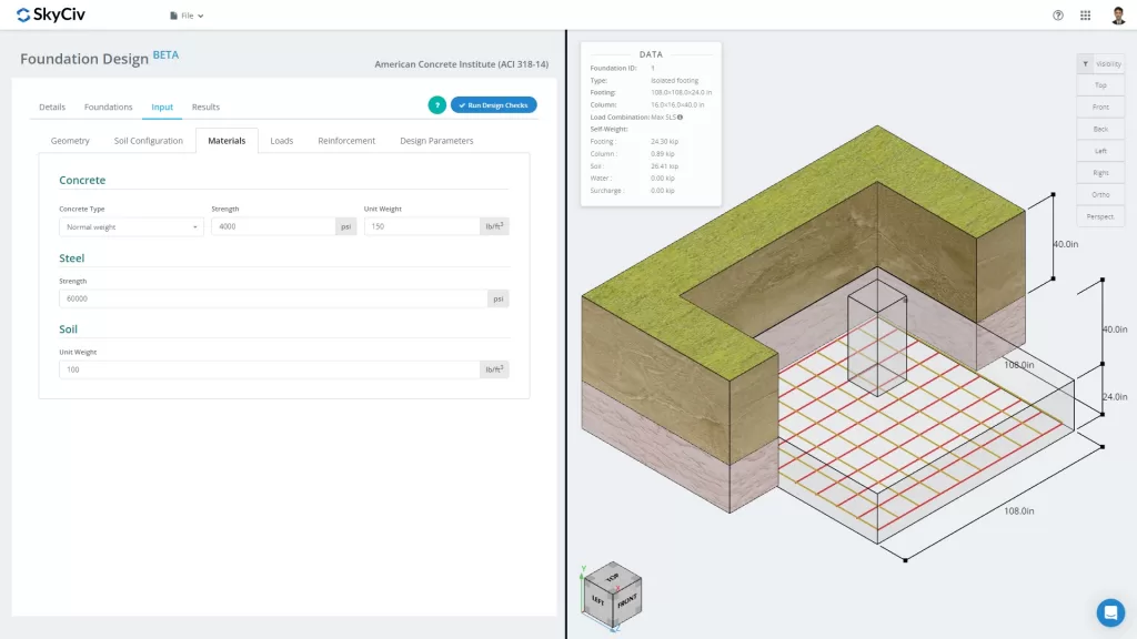
figura 4. Scheda Fondazione
La “Ingresso” La scheda separa le categorie di input inclusa la Geometria, Configurazione del suolo, materiale, Carichi, Rinforzo e varie. Questi input aggiorneranno automaticamente la grafica 3D nella scheda destra dello schermo. Il contenitore giusto verrà discusso nell'ultima parte di questa documentazione.
Esaminiamo le diverse categorie di input in modo un po’ più dettagliato:
Geometria
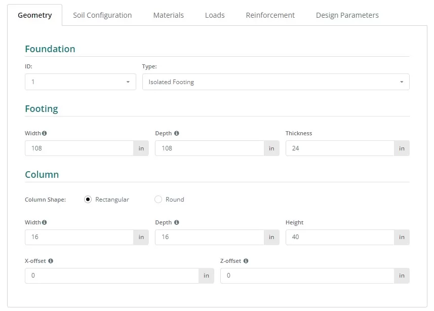
figura 5. Geometria nella scheda di sinistra.
Vedi figure 6 e 7 per la nomenclatura delle dimensioni della fondazione e della colonna:
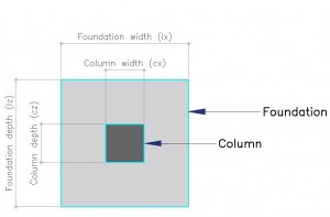
figura 6. Fondazione con denominazione
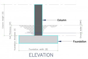
figura 7. Veduta in prospetto della Fondazione
Configurazione del suolo
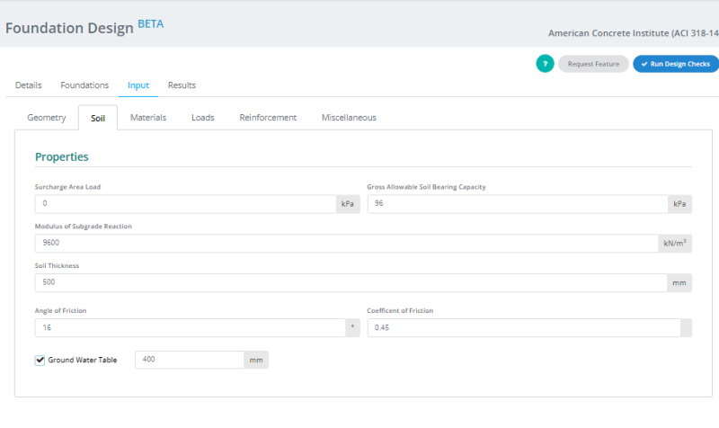
figura 8. Configurazione del suolo nella scheda di sinistra.
Nota:
- I valori del terreno si trovano solitamente nella Relazione Geotecnica.
- Spunta il “Tavola delle acque sotterranee” casella per definire l'altezza della falda freatica.
- Il valore del modulo di reazione del sottofondo si aggiorna automaticamente quando il valore della "Capacità portante lorda ammissibile del terreno"” è cambiato. Tuttavia, gli utenti possono comunque sovrascrivere questo valore.
materiale
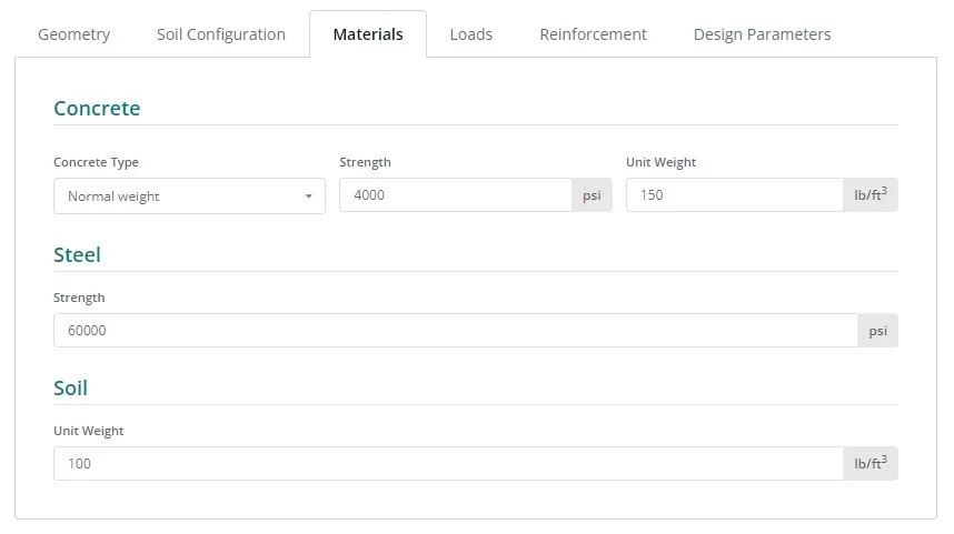
figura 9. materiale pulsante nella scheda di sinistra.
Carichi
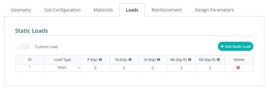
figura 10. Carichi pulsante nella scheda di sinistra.
Rinforzo
Generalmente, il basamento isolato comprende solo i rinforzi inferiori, sebbene sia possibile accedere a un'opzione per i rinforzi superiori facendo clic sul pulsante corrispondente. Aggiornare i rinforzi è facile, seleziona la dimensione della barra nell'elenco a discesa e inserisci la spaziatura necessaria.
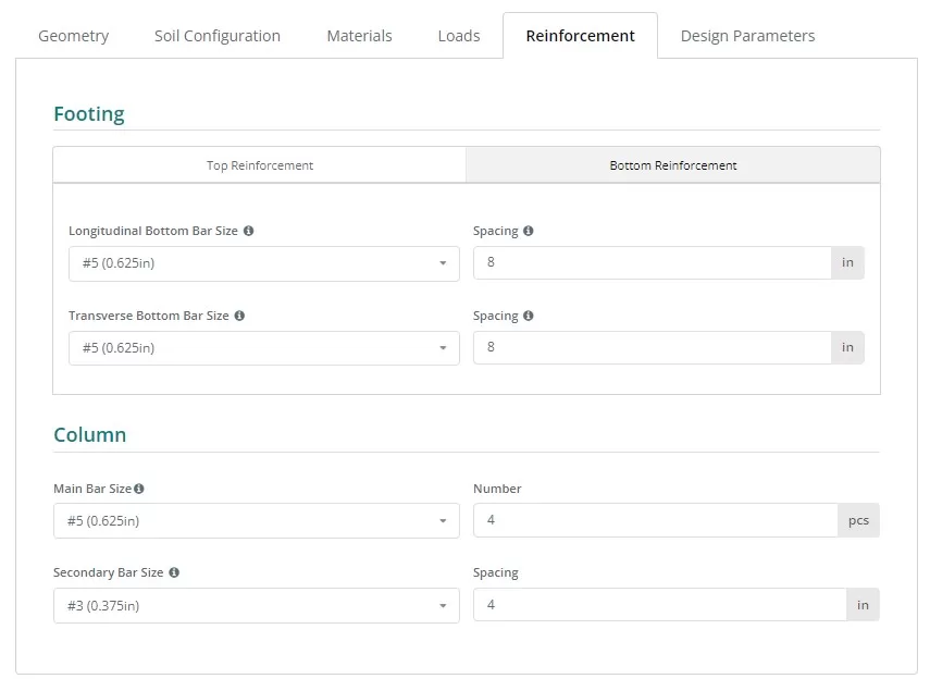
figura 11. Rinforzo pulsante nella scheda di sinistra.
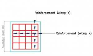
figura 12. Dettagli di rinforzo.
Riferimento del codice dell'armatura:
- ASTM615 – Società americana per i test e i materiali 615 : Specifiche standard per barre in acciaio al carbonio deformate e lisce per rinforzo in calcestruzzo
- N – Tondo per cemento armato australiano Classe N
- PNS49 – Standard nazionale delle Filippine 49 : Barre d'acciaio per il rinforzo del calcestruzzo – Specifica.
- E2 – Eurocodice Armatura P
miscellaneo
Questa scheda contiene altri input necessari per il codice di progettazione scelto. Contiene anche alcuni input per controllare la dimensione della mesh del modello a elementi finiti e il fattore di taglio del bordo di punzonamento per la verifica del taglio di punzonamento.
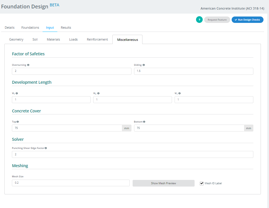
figura 13. miscellaneo pulsante nella scheda di sinistra.
IV. risultati
Il tuo progetto produrrà la tabella dei risultati dopo aver fatto clic sul pulsante Esegui verifica progetto. Ogni colonna, tranne gli ultimi due, rappresenta un controllo di progettazione completato dal modulo Foundation. I valori sono rapporti di utilità; qualsiasi cosa uguale o inferiore 1.0 è un PASSATO, e niente oltre 1.0 è un FALLIMENTO. Le ultime due colonne contengono lo stato codificato a colori e l'opzione per accedere o scaricare il report nei formati HTML o PDF.
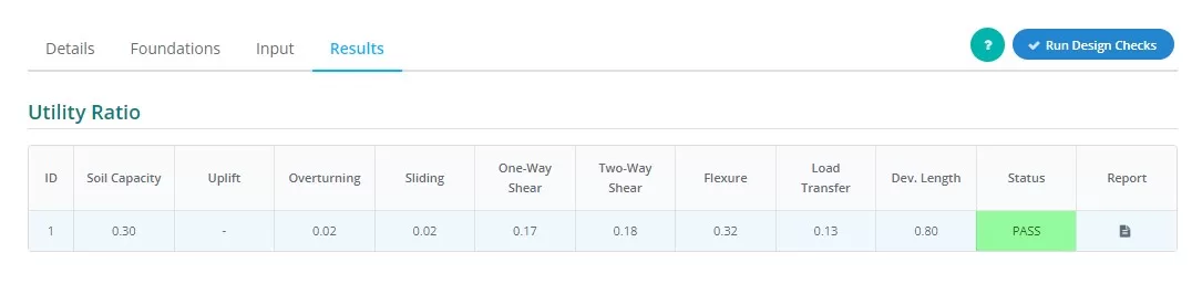
figura 14. risultati Uscita nella scheda di sinistra.
Riepilogo delle rappresentazioni delle colonne:
- Pressione del suolo
Rapporto tra la pressione del suolo derivante dai carichi sperimentali e la pressione ammissibile del suolo. - Sollevamento
Determina se esiste un sollevamento sul carico - Ribaltamento
Rapporto tra il momento ribaltante sperimentato e il momento ribaltante ammissibile. - Scorrevole
Rapporto tra la forza di scorrimento sperimentata e la resistenza allo scorrimento. - Taglio unidirezionale
Rapporto tra la domanda di taglio unidirezionale e la capacità. - Taglio bidirezionale
Rapporto tra la domanda di taglio a due vie e la capacità. - Flessione
Rapporto tra domanda flessionale e capacità flessionale. - Trasferimento di carico
Rapporto tra la resistenza nominale e quella effettiva del cuscinetto. - Lunghezza di sviluppo
Rapporto tra la lunghezza di sviluppo nominale e quella effettiva. - Stato
Indica che il progetto della fondazione è Metà dell'altezza del muro dal fondo della base per il caso del o FALLIRE - rapporto
Fare clic per vedere il calcolo dettagliato del progetto della fondazione.
V . Render
infine, situato nella parte destra dello schermo c'è il renderer 3D per aiutare gli utenti a visualizzare gli input. Nell'angolo in alto a sinistra sono presenti i dati di riepilogo del modello contenenti le informazioni di base sulla fondazione, e nell'angolo opposto ci sono le impostazioni di visibilità. Gli utenti possono selezionare gli oggetti che desiderano mostrare o nascondere e scegliere l'orientamento della grafica che desiderano vedere.
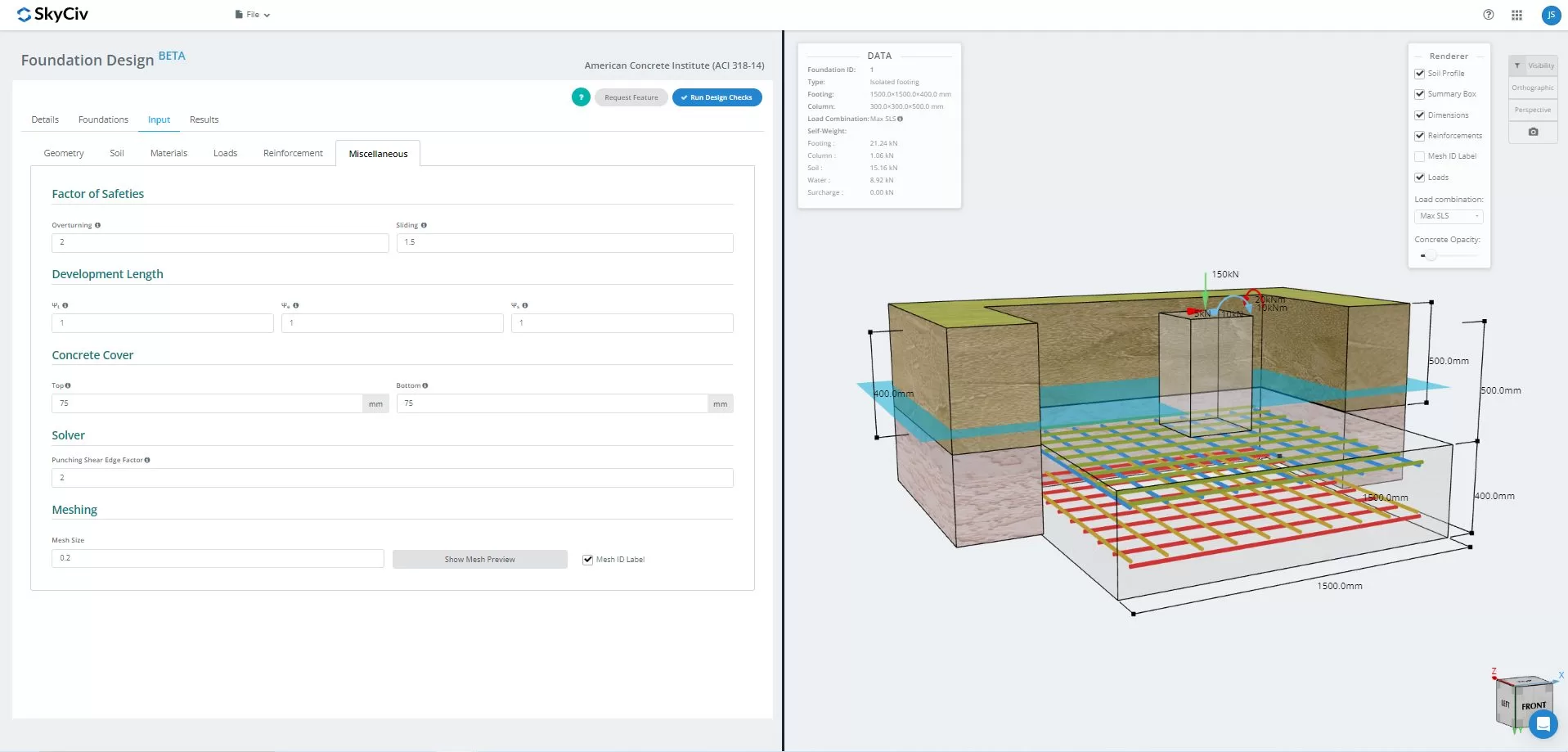
Figura 15.3D Rappresentazione grafica del modello
Una volta risolto, gli utenti possono visualizzare i risultati FEA della pressione del suolo, e analisi del braccio di legno in 3D. I risultati possono essere scambiati tra tutte le combinazioni di carico, comprese le buste. È inoltre possibile scaricare uno screenshot della vista corrente.
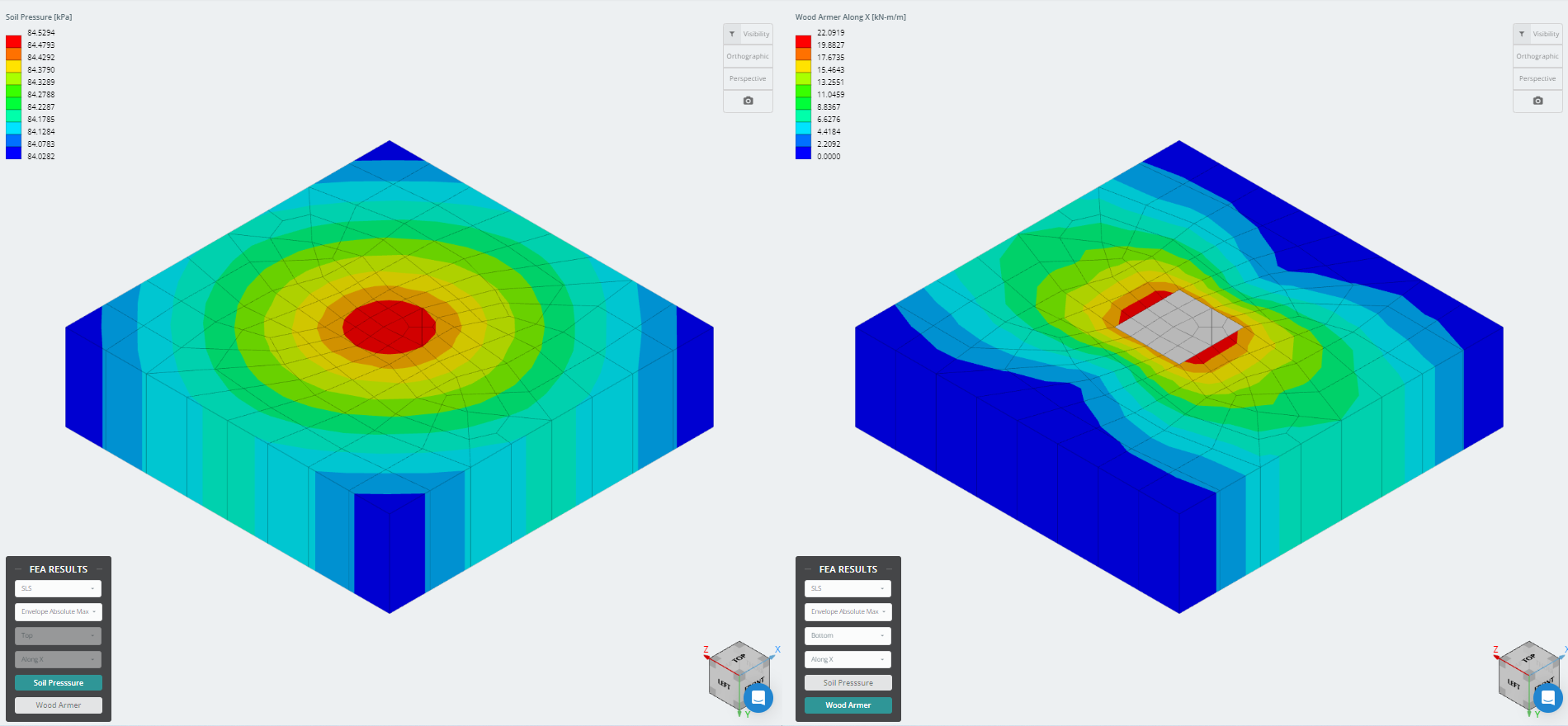
figura 16. Risultati dell'analisi degli elementi finiti
Vuoi provare il software Foundation Design di SkyCiv? Il nostro strumento consente agli utenti di eseguire calcoli di progettazione della fondazione senza scaricare o installare!
Riferimento:
- Requisiti del codice di costruzione per calcestruzzo strutturale (ACI 318-14) Commento ai requisiti del codice edilizio per il calcestruzzo strutturale (ACI 318R-14). American Concrete Institute, 2014.
- Taylor, Andrea, et al. The Reinforced Concrete Design Handbook: un compagno di ACI-318-14. American Concrete Institute, 2015.