
A flange plate moment connection carries bending across a beam to column joint by turning the beam’s moment into a force couple: tension in one flange plate, compressione nell'altro. A separate web plate carries the shear. That division is what makes the connection straightforward to design and to build, because each component has one job.
The usual arrangement is a plate bolted to the beam flange and welded to the column. Where the frame is shop-assembled, the whole connection can be welded instead. The web plate is normally bolted at the beam web and welded to the column.
SkyCiv Connection Design checks the whole assembly to AISC 360-16 nell'ASD o LRFD. You enter the beam and column sections, the plate dimensions, the bolts and welds, and the loads; it returns every check with its utilization ratio and the clause behind it.
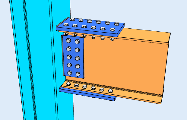
Vista dall'alto
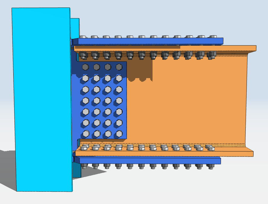
Vista dall'alto
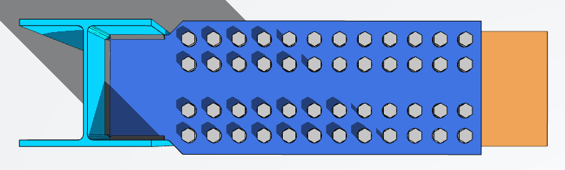
Designing a Flange Plate Connection in SkyCiv
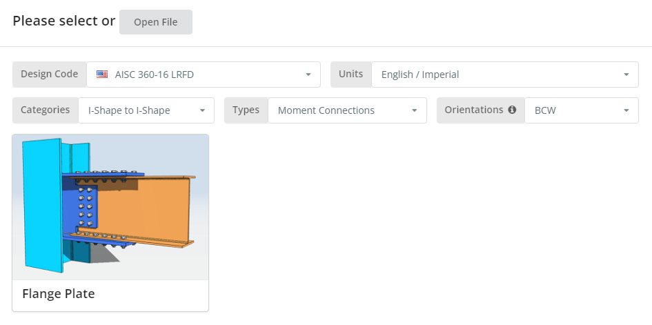
Il codice di progettazione può essere AISC 360-16 ASD o LRFD, e unità inglesi/imperiali o SI/metriche. Orientation is BCF or BCW; hover the tooltip for what each means. Clicca il “Flangia Piastra” piastrella.
Scheda Dettagli
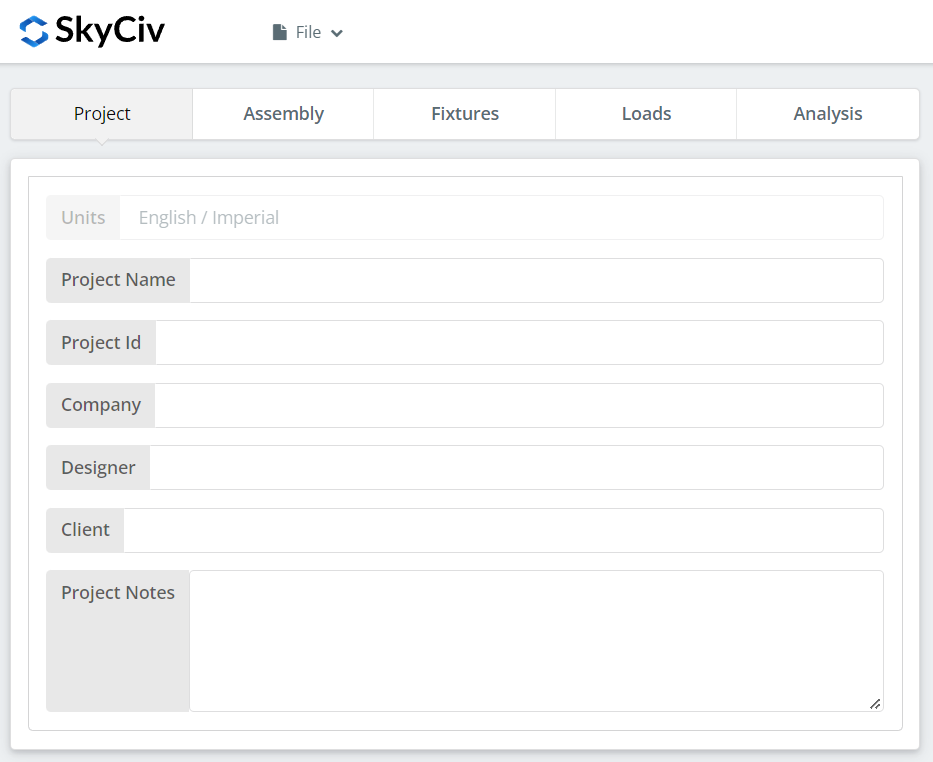
Registra qui i dettagli del progetto. Niente di tutto ciò cambia i calcoli, ma riporta nel rapporto.
Scheda assemblaggio
Tre schede si trovano sotto Assemblaggio: la Colonna, il Fascio, e la connessione, which holds both the flange plate and the web plate.
Scheda Colonna
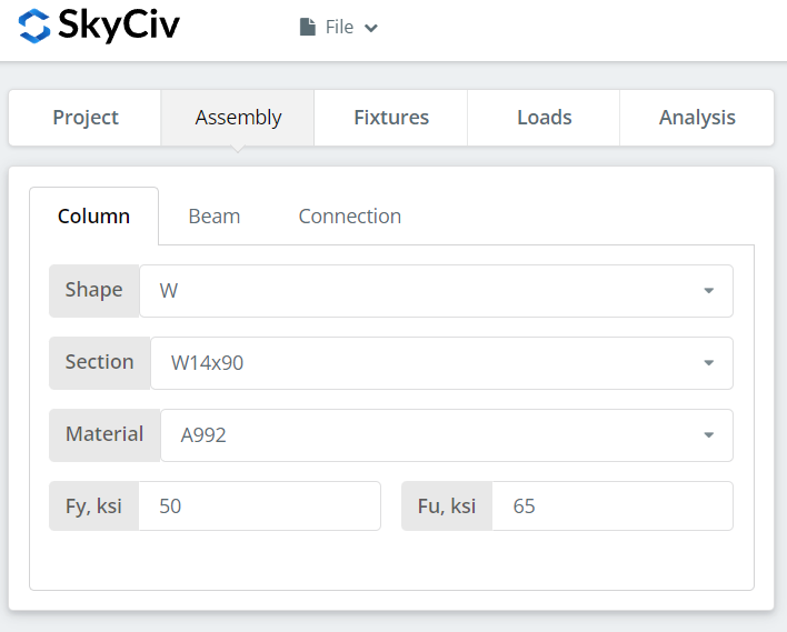
Specificare la sezione e la qualità del materiale della colonna. A992 e A36 sono nell'elenco; per qualsiasi altra cosa scegli Personalizzato e inserisci Fy e Fu.
Scheda Trave
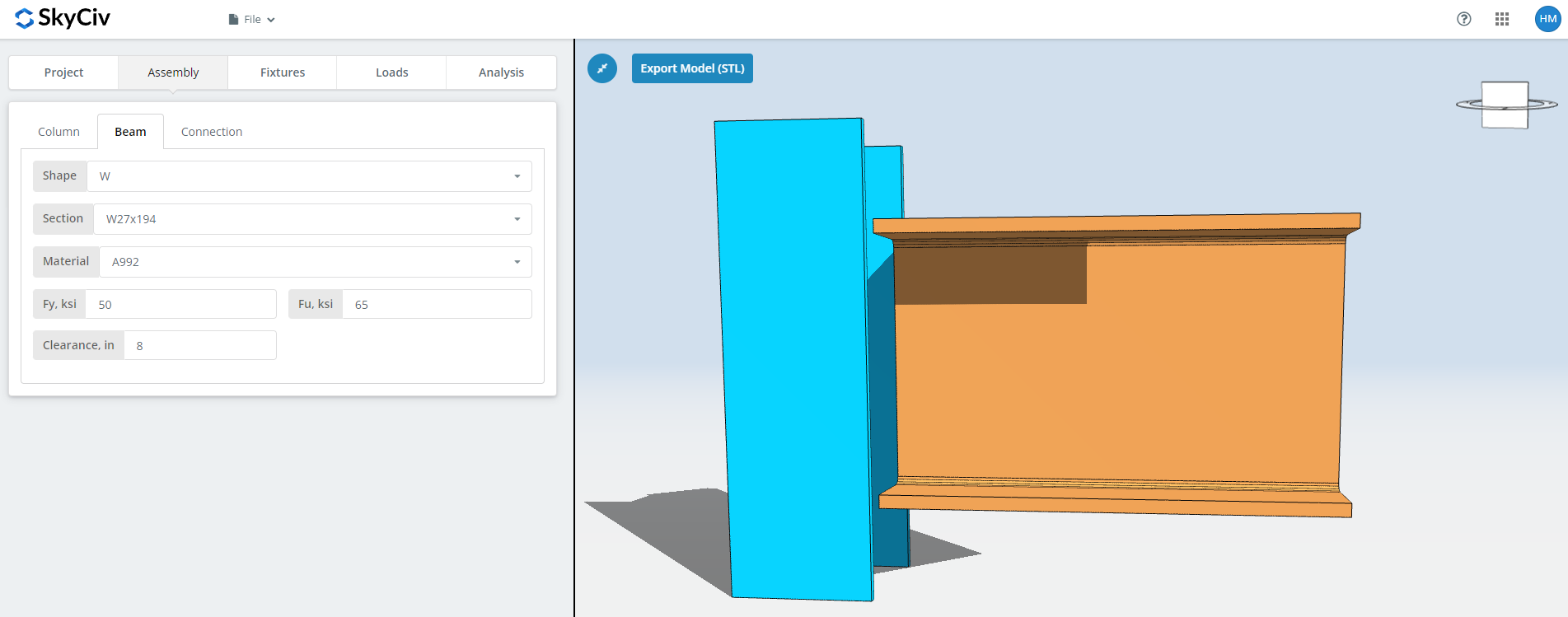
Gli stessi input per la trave, plus the beam clearance.
Scheda Connessione: Flangia Piastra
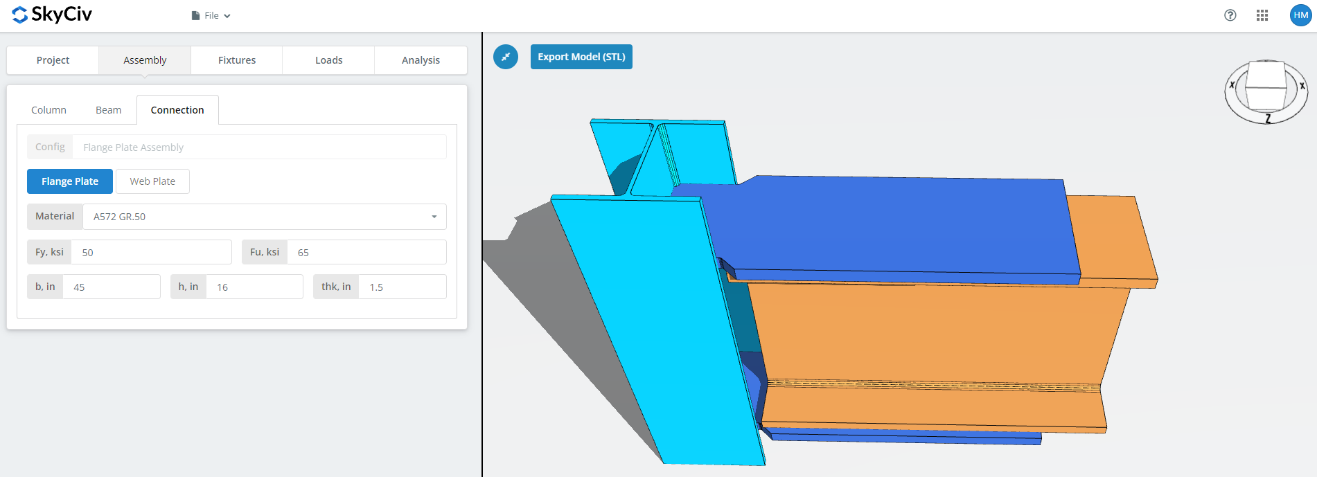
Set the flange plate properties: grade A36, A992 or A572 Gr.50, o Personalizzato con il tuo Fy e Fu, then b (larghezza), h (altezza) e thk (spessore).
This is the plate that carries the moment, so its area and the bolt group in it are what the moment capacity comes down to. Watch the 3D renderer as you type and check there is room for the bolts or welds you will define on the Fixtures tab.
Scheda Connessione: Piastra Web
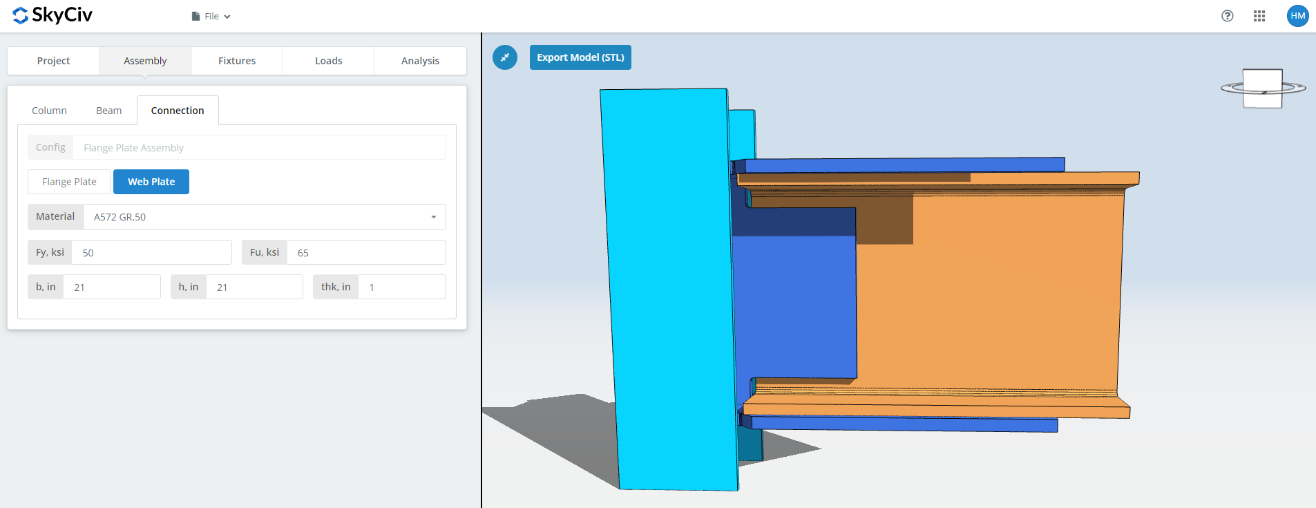
The same fields for the web plate. This one carries the shear, so its depth and bolt group are sized against the vertical load rather than the moment. Check the renderer again before moving on.
Infisso 1 Scheda
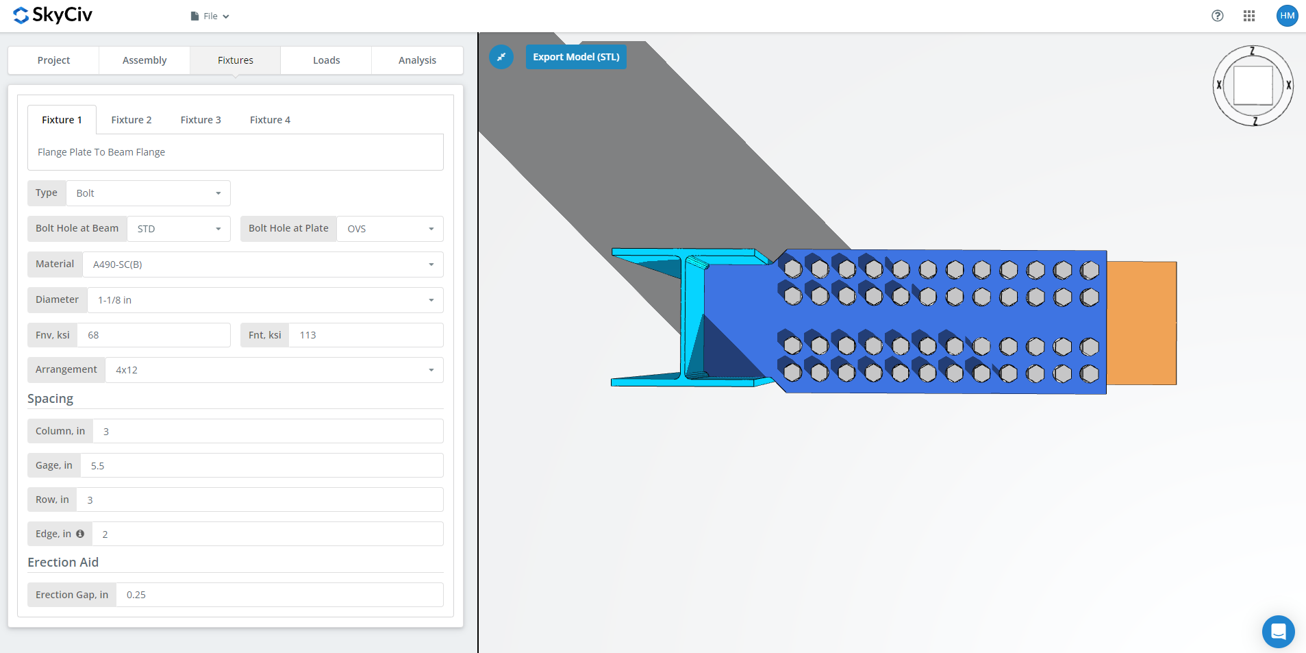
Infisso 1 is the flange plate to beam flange connection. Può essere imbullonato o saldato; questa procedura dettagliata utilizza imbullonati.
Primo, the bolt hole types at the beam flange and at the flange plate. I produttori di solito richiedono fori standard (malattie sessualmente trasmissibili) in the member and oversized holes (OVS) in the flange plate, che acquista la tolleranza adeguata sul campo.
Successivamente, il materiale o la qualità del bullone: A307, A325, A490 o personalizzato. A325 e A490 sono gradi all'interno di ASTM F3125, che ha consolidato le vecchie specifiche autonome. Scegliere N o X per una connessione di tipo cuscinetto e SC per una connessione critica allo scorrimento.
I giunti critici per lo scivolamento hanno una capacità di progettazione dei bulloni inferiore rispetto al tipo con cuscinetti, quindi usali dove lo scivolamento conta davvero: fori maggiorati o asolati, inversione di carico, o stanchezza. In questo esempio, using OVS holes in either the beam or the plate means the bolts are automatically checked as slip-critical. Tra N e X, X indica la maggiore capacità di taglio del bullone, ma i fili devono essere esclusi dal piano di taglio, e l'erettore deve saperlo. Tra SC(A) e SC(B), SC(B) offre una capacità maggiore e richiede una superficie di contatto preparata in modo più accurato, ad esempio la sabbiatura commerciale SSPC-SP6.
Quindi il diametro del bullone, dal 5/8″ a 1-1/2″ o gli equivalenti metrici, e la disposizione, fino a 8 file di bulloni e 12 colonne a bullone, with the row spacing, column spacing and gage. La “bordo” l'input è la distanza dall'estremità della trave alla prima colonna di bulloni.
Scorso, il divario di erezione. Questo è lo spazio che consente alla trave di essere posizionata in loco. Costa capacità, quindi specificatelo solo dove l'erezione ne ha effettivamente bisogno, and say so on the drawing when you do.
Infisso 2 Scheda
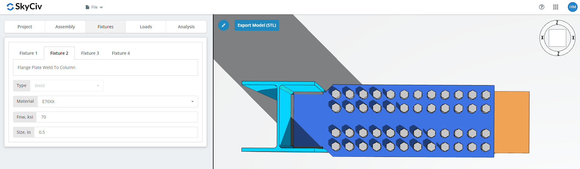
Infisso 2 is the flange plate to column connection, to the column web and flange for BCW or to the column flange for BCF. This one is welded only.
Specificare il materiale di saldatura, oppure scegli "Personalizzato".’ e inserisci Fnw se l'elettrodo desiderato non è elencato, quindi la dimensione della saldatura.
Infisso 3 Scheda
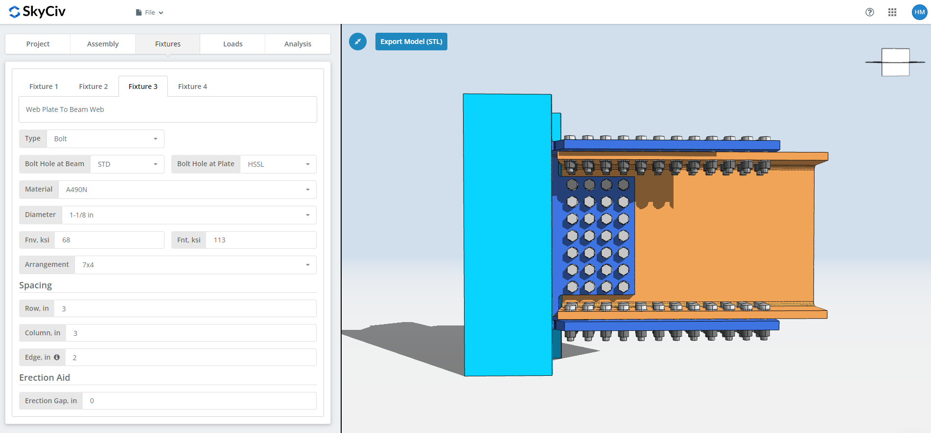
Infisso 3 is the web plate to beam web connection. Può essere imbullonato o saldato; questa procedura dettagliata utilizza imbullonati.
Primo, the bolt hole types at the beam web and at the web plate. I produttori di solito richiedono fori standard (malattie sessualmente trasmissibili) nell'elemento e nei fori orizzontali a fessura corta (HSSL) in the web plate.
Successivamente, il materiale o la qualità del bullone: A307, A325, A490 o personalizzato, with the same N, X and SC choices as Fixture 1. The slip-critical and thread-exclusion notes above apply here too.
Quindi il diametro del bullone, dal 5/8″ a 1-1/2″ o gli equivalenti metrici, e la disposizione, fino a 12 file di bulloni e 12 colonne a bullone, con la spaziatura delle righe e delle colonne. La “bordo” l'input è la distanza dall'estremità della trave alla prima colonna di bulloni.
Scorso, il divario di erezione, as above.
Infisso 4 Scheda
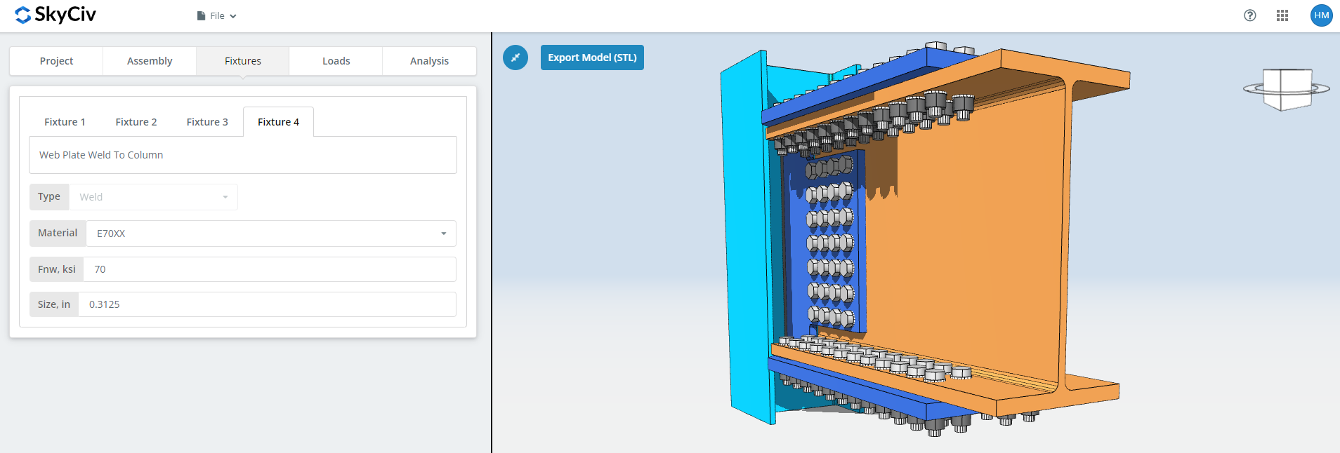
Infisso 4 is the web plate to column web or flange connection, and like Fixture 2 it is welded only. Specificare il materiale di saldatura, o "Personalizzato".’ with your own Fnw, and the weld size.
Per ulteriori informazioni sul lato degli elementi di fissaggio, vedere la documentazione su bulloni e saldature.
Scheda Carichi
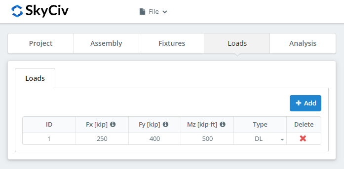
Enter the horizontal axial load under ‘Fx’, the vertical shear under ‘Fy’, and the strong axis moment under ‘Mz’.
Match the loads to the design method you picked at the start. LRFD prende in considerazione i carichi fattorizzati rispetto alla resistenza di progetto; L'ASD sopporta i carichi di servizio rispetto alla resistenza ammissibile. Il software non è in grado di riconoscere cosa hai digitato.
Scheda Risultati
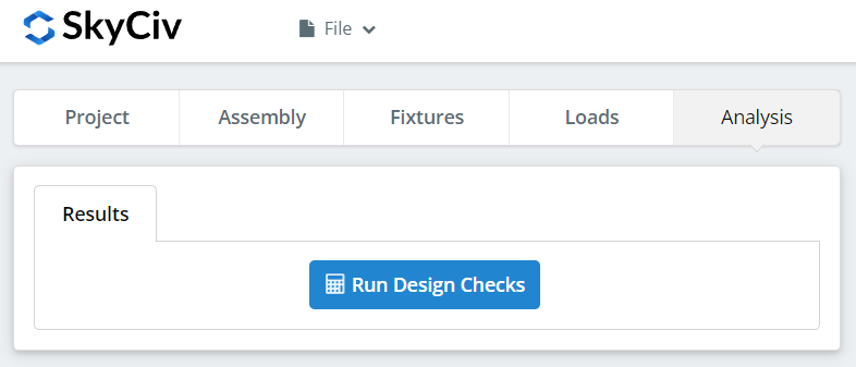
Clic “Esegui controlli di progettazione”. Tutto ciò che manca nelle schede precedenti viene contrassegnato qui anziché essere impostato automaticamente come predefinito.
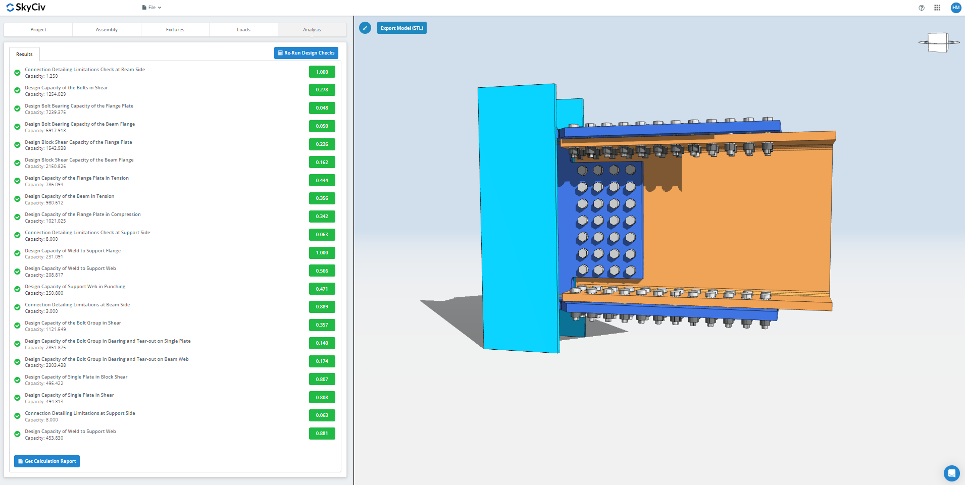
Il riepilogo mostra se la connessione è riuscita, con un rapporto di utilizzo rispetto a ciascun controllo. Se ha fallito, modificare gli input nelle schede precedenti e fare clic “Rieseguire i controlli di progettazione”. Quando passa, “Visualizza il rapporto di calcolo” apre il rapporto dettagliato.
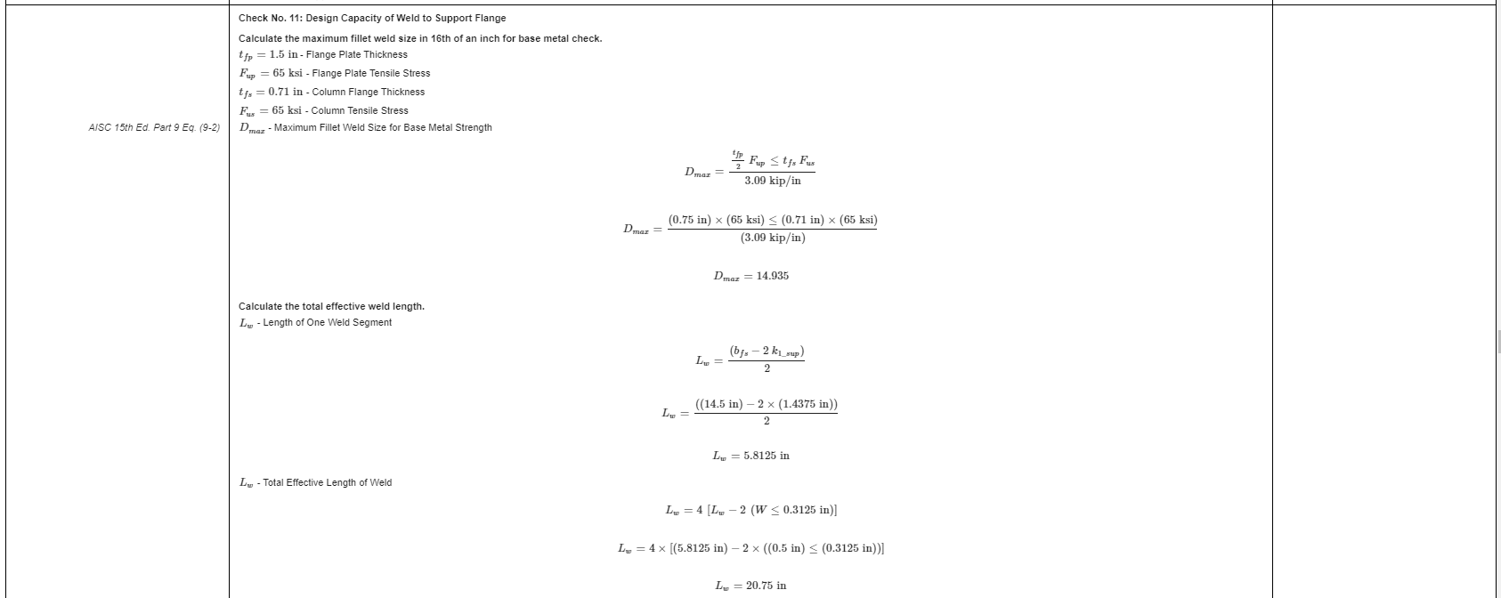
Questo è un estratto del rapporto. Ogni controllo riporta il riferimento al manuale o alla specifica AISC, e la lavorazione segue l'ordine utilizzato dalle specifiche, in questo modo un tecnico revisore può leggerlo riga per riga invece di eseguire il reverse engineering di un numero.
Ecco una copia in PDF del rapporto di calcolo dettagliato completo: Rapporto di progettazione della connessione.
Provalo tu stesso
Pick the flange plate connection, inserisci le tue sezioni, piatti, bolts and loads, e vedere ogni controllo con il relativo riferimento al codice. Funziona nel browser, senza niente da installare.
Vedi anche il calcolatore di connessione della piastra flangiata, il calcolatore della connessione momento che per il connessioni di momento panoramica.
