
Le connessioni in acciaio elencate in questo articolo sono progettate in conformità con lo standard australiano AS 4100:2020, Manuale di connessione dell'Australian Steel Institute 1, e le guide alla progettazione dell'Australian Steel Institute 1-5.
Campo di applicazione dell'AS 4100 Modulo
Prima di esaminare i tipi di connessione, vale la pena essere chiari su ciò che il modulo copre sotto AS 4100.
AS 4100:2020 la progettazione in SkyCiv riguarda le connessioni a taglio tra le sezioni a I, in unità metriche. Connessioni del momento, le giunzioni e le connessioni di rinforzo sono esterne all'AS corrente 4100 ambito.
Trave universale a colonna universale
Le connessioni trave-colonna sono tra i tipi di connessione più comuni nella progettazione in acciaio. Le connessioni AS in SkyCiv sono costruite attorno a una trave supportata che incornicia un membro di supporto, e l'orientamento può essere impostato su un supporto della flangia della colonna, un supporto web della colonna, o un supporto per l'anima della trave.
Questo terzo orientamento significa che è possibile utilizzare gli stessi quattro tipi di connessione anche da trave a trave, non solo trave su colonna.
È possibile progettare una sola connessione a un nodo alla volta. Quando si tratta di connessioni back-to-back, si consiglia di assumere ipotesi conservative sul percorso del carico.
Collegamenti a taglio
Una connessione a taglio è una connessione semplice. È dettagliato sopportare la reazione finale della trave e ruotare in corrispondenza del giunto anziché sopportare il momento finale, che è ciò che lo separa da una connessione momentanea. Nel modulo AS è progettato per il solo taglio, senza carico assiale concomitante.
Per il design AS, sono disponibili i seguenti tipi di connessione a taglio:
Ciascuno dei quattro è disponibile trave e flangia della colonna, trave all'anima della colonna, e rete da trave a trave.
-

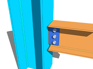
- Piastra laterale web – Flangia trave e colonna
-
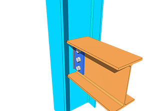
- Piastra laterale web – Trave a colonna Web
-
- Piastra terminale flessibile – Flangia trave e colonna

-
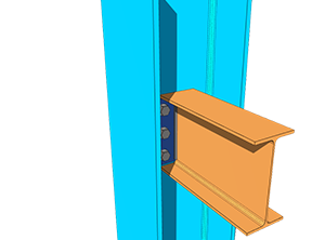
- Piastra terminale flessibile – Trave a colonna Web
-
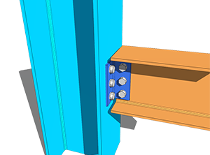
- Angolo singolo – Flangia trave e colonna
-
- Angolo singolo – Trave a colonna Web
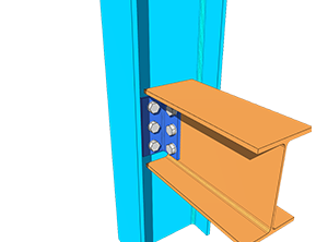
-
- Doppio angolo – Flangia trave e colonna
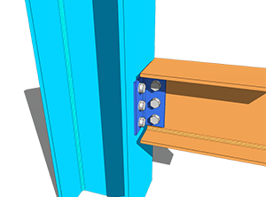
-
- Doppio angolo – Trave a colonna Web
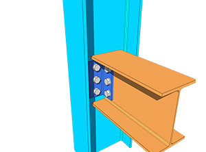
La progettazione delle suddette connessioni a taglio si è basata principalmente sulle Guide di Progettazione ASI 3, 4 e 5. Le formule di riferimento sono state tratte dall'AS 4100:2020 Manuale, mentre il resto dei calcoli e dei criteri sono stati presi dal Manuale di Collegamento ASI 1.
Coefficiente di gruppo dei bulloni
Per flessibilità sulla disposizione dei bulloni e sulla spaziatura dei bulloni, SkyCiv ha adattato il metodo ICOR e l'analisi anelastica per determinare il coefficiente C del gruppo di bulloni, che viene poi utilizzato per calcolare la capacità di taglio del gruppo di bulloni e la capacità portante del bullone.
Il metodo del centro di rotazione istantaneo (ICOR) usa l'iterazione per individuare l'IC del gruppo di bulloni. SkyCiv utilizza il proprio risolutore per queste iterazioni. La posizione dell'IC è inclusa nei calcoli, ma le iterazioni non vengono mostrate, mantenere il rapporto conciso e leggibile.
L'equazione utilizzata per calcolare la forza per bullone utilizzando l'analisi anelastica si basa sull'equazione AISC. (7-1) alla pagina 7-7 del Manuale AISC 15a edizione. L'equazione è mostrata di seguito.
[math] R = R_{ult}\left(1-e^{-10\Delta}\right)^{0.55} [math]
Questo è un metodo preso in prestito per il risolutore del gruppo di bulloni, non un cambiamento del codice di progettazione. Le capacità stesse sono ancora controllate da AS 4100:2020.
Poiché la capacità del gruppo di bulloni ha adattato il metodo AISC, seguono anche le disposizioni per determinare l'eccentricità di progetto del gruppo di bulloni 10-9 dell'AISC 15a ed. Questo vale per la connessione AS Web Side Plate di SkyCiv.
L'eccentricità viene gestita in modo diverso per ciascun tipo. Per connessioni ad angolo singolo, entrambe le gambe NSL e OSL sono progettate con eccentricità di carico. Per connessioni ad angolo doppio, solo la gamba NSL è progettata con eccentricità, poiché la gamba OSL è bilanciata simmetricamente rispetto alla linea di forza. Anche per le connessioni con piastra terminale flessibile non è presente eccentricità, poiché il carico agisce direttamente sul centro del gruppo bulloni. Ogni gruppo di bulloni senza eccentricità assume il coefficiente C del bullone come numero totale di bulloni nel gruppo.
Tipi di dispositivi
Ciascuna interfaccia può essere impostata come dispositivo imbullonato o saldato, alla trave e al supporto.
Per il caso imbullonato, vedere la documentazione su bulloni; per la cassa saldata, vedere saldature.
Limitazioni di dettaglio
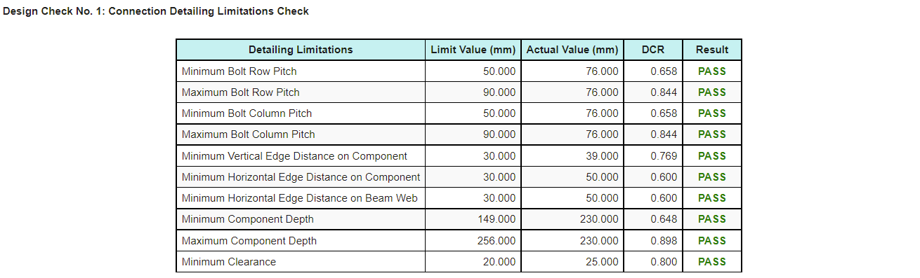
Limitazioni di dettaglio, le verifiche di messa a punto delle connessioni, sono inclusi nel progetto della connessione AS. La maggior parte di essi si basa sulle guide di progettazione ASI 3-5, mentre alcuni seguono un approccio ingegneristico intuitivo.
Questi controlli rilevano la connessione che soddisfa ogni calcolo di resistenza e tuttavia non può essere costruita o eretta, che è una modalità di fallimento che i soli controlli di forza non riusciranno a trovare.
Nella scheda Risultati viene visualizzato un risultato superato o negativo per le limitazioni dei dettagli, quindi può essere identificato rapidamente. Il rapporto di calcolo produce anche una tabella, mostrato sotto, quindi l'elemento che deve essere modificato è facile da individuare.
Altri tipi di connessione
Se desideri vedere più tipi di connessione aggiunti in AS 4100, puoi contattare Supporto SkyCiv.
Provalo adesso
Scegli una piastra laterale in rete, piastra terminale flessibile, angolo singolo o doppio angolo, entra nel tuo raggio, supporto e carichi, e il modulo restituisce ogni assegno con il suo rapporto di utilizzo e il riferimento dietro di esso, insieme alla tabella dei limiti di dettaglio. Funziona nel browser, senza niente da installare, e puoi farlo senza un account.
Puoi raggiungerlo anche attraverso il Calcolatrice gratuita per la progettazione di connessioni in acciaio.
Iscriviti all'account gratuito
Un account gratuito ti consente di salvare e ricaricare i file di connessione, cosa che lo strumento gratuito non fa. Ti dà anche accesso al resto di SkyCiv software strutturale, compreso il 3D strutturale.
Design della connessione autonomo
Si desidera utilizzare solo il modulo di progettazione della connessione? Fare clic sul pulsante in basso per i prezzi autonomi.
