Panoramica di esempio
In questo esempio avanzato continuerai a studiare il comportamento della trave precedente, ma ora in termini di analisi statica non lineare.
L'analisi statica lineare e di instabilità lineare eseguita in precedenza consente di analizzare e ottimizzare rapidamente la struttura. Tuttavia, a volte è necessario vedere il “quadro reale”.’ del fallimento. Guarda come è distribuita la plasticità negli elementi, quali sono i valori e come l'imperfezione geometrica influisce sull'instabilità.
Per vedere questo quadro finale di fallimento deve essere considerata l’analisi statica non lineare. Questa analisi considera i carichi esterni per porzioni (o passi), dove la non linearità materiale e geometrica considerata per determinare la forma deformata dallo stress in ogni fase.
Step 1. Perfezionamento della maglia
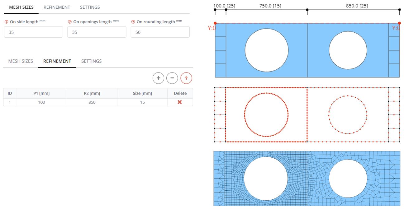
Nel pannello Mesh definire la dimensione della mesh per tutti i bordi e le aperture 35 mm, rendendo la mesh del modello globale più grossolana rispetto a prima. Quindi vai alla scheda Perfezionamento. Definire la riga nella tabella e la zona di affinamento della mesh a partire da (P1) 100 mm e fine (P2) a 850 mm dall'inizio della trave. La dimensione della maglia in questa zona è 15 mm. Genera la mesh per il modello e osserva come viene creata la mesh più densa nel primo pannello web.
Step 2. Proprietà dei materiali non lineari
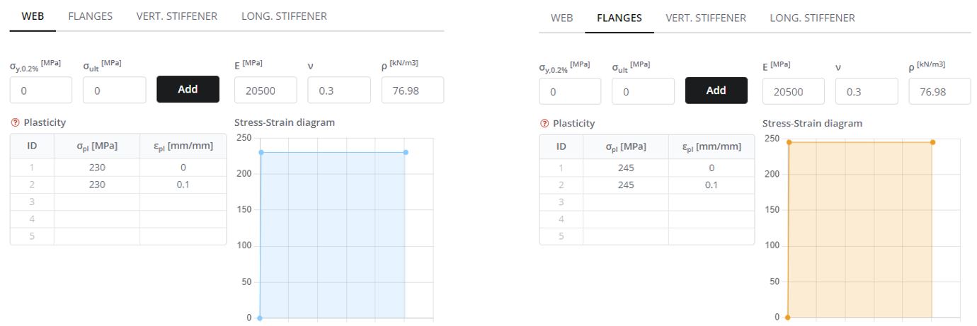
Nel pannello Materiali definire le proprietà di sollecitazione e deformazione plastica dei materiali. Le parti della trave sono realizzate in acciaio con valori di tensione di snervamento pari a 230 MPa per il web e 245 MPa per altri componenti.
Definire un diagramma bilineare che includa due zone: lineare e plastico. Primo modulo di elasticità impostato (E) per acciaio. Nella seconda riga della tabella crea "plastic’ zona con lo stesso valore di sollecitazione plastica Ripetere questa procedura per gli altri componenti della trave come le flange e gli irrigidimenti con la sollecitazione plastica di 245 MPa.
Step 3. Imperfezioni della rete
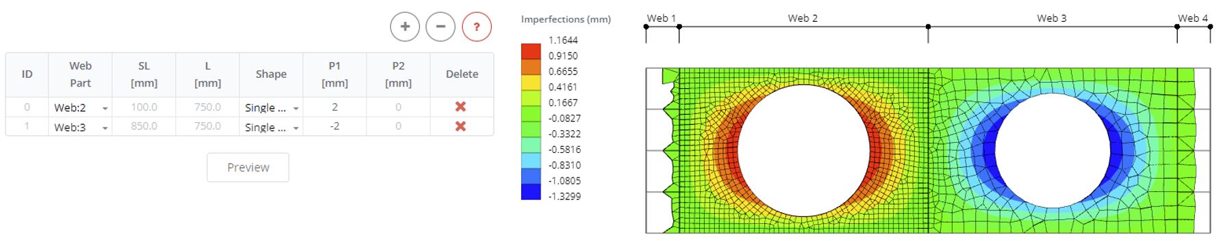
Definire le imperfezioni sui pannelli web 2 e 3. Definire due righe e selezionare i pannelli web. Definire la direzione dell'imperfezione e la grandezza (P1) come 2 mm per un pannello e -2 mm per un altro pannello. Fare clic sul pulsante Anteprima per vedere come influisce sulla geometria del modello FE durante l'analisi.
Step 4. Carico di spostamento
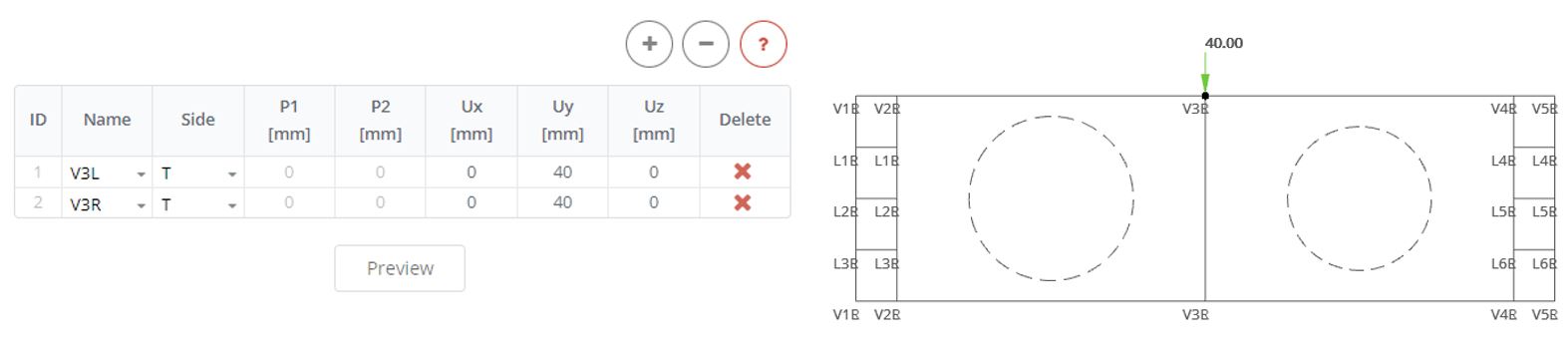
Rimuovere le forze precedentemente definite dagli irrigidimenti. Quindi nel pannello Irrigidimenti di spostamento applicare un carico di spostamento lungo l'asse y di 40 mm.
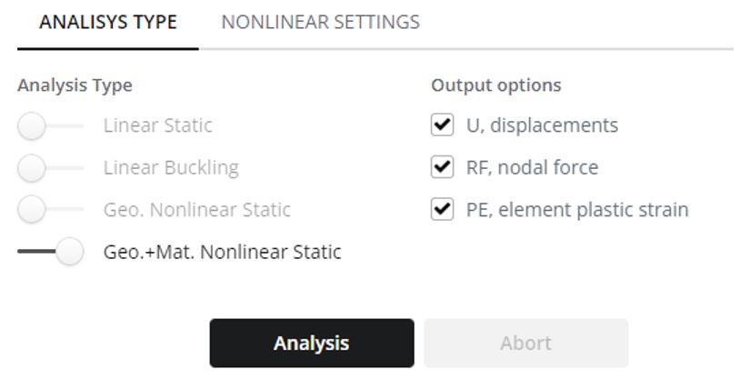
Step 5. Analisi non lineare
Nel pannello Analisi selezionare il tipo di analisi statica non lineare della geometria e del materiale. Fare clic sul pulsante Analisi.
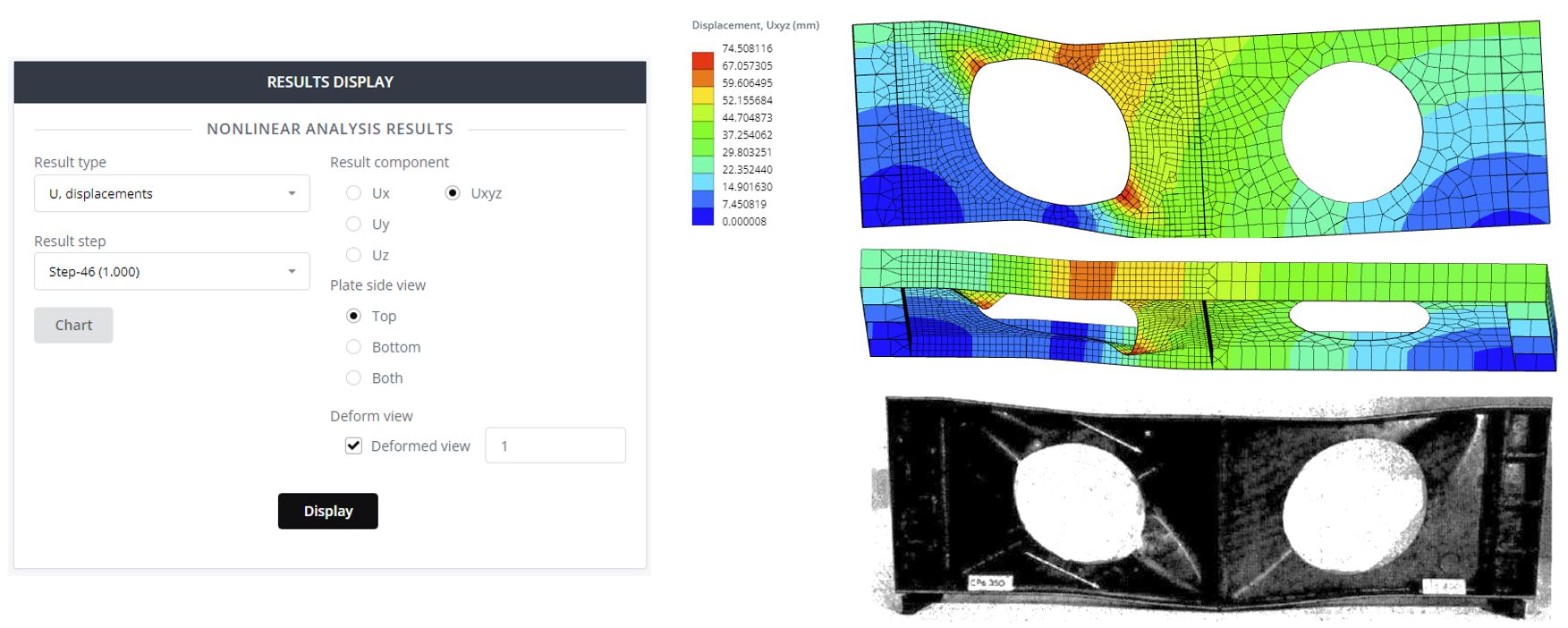
Step 6. Risultati di spostamento
Nel Passaggio dei risultati selezionare il passaggio finale (1.0). Seleziona il componente di spostamento e includi la vista deformata con una scala di 1.
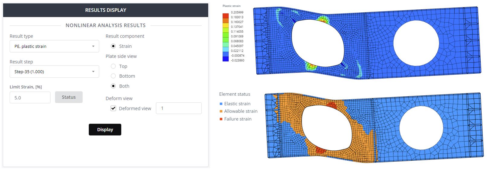
Step 7. Risultati di plasticità
Selezionare Vista laterale piastra entrambi e fare clic su Visualizza per visualizzare il grafico del contorno della deformazione plastica. Qui, un valore pari a zero significa che l'elemento non ha plasticità. Definire nel campo Deformazione limite 5% e fare clic sul pulsante Stato. Di conseguenza, vedrai le zone sicure e non sicure della struttura.
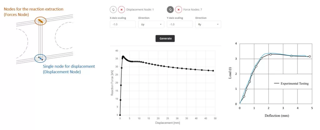
Step 8. Grafico carico-spostamento
L'ultimo oggetto che verrà analizzato è il diagramma carico-spostamento. Questo diagramma permette di vedere la forza di rottura critica applicata alla trave. Vai alla Mappa nel menu principale. In Nodo di spostamento si seleziona il nodo da cui è possibile estrarre la deflessione verticale. Questo è il centro della trave e il punto inferiore. Quindi per i Nodi delle Forze scegli i nodi da cui viene estratta la forza di reazione verticale totale. Qui due opzioni: 1 – tutti i nodi dei supporti, 2 – nodi di carico di spostamento. Quindi si seleziona la direzione della reazione e dello spostamento (Ru e Uy). Definire i fattori di scala e fare clic sul pulsante Genera. Il diagramma ottenuto è vicino a quello ricevuto dalla prova sperimentale.
Calcolatore gratuito di travi
Scopri la soluzione definitiva per l'analisi rapida e precisa delle strutture di travi con SkyCiv Beam Software. Provalo subito con il nostro strumento Beam gratuito che presenta funzionalità come Calcolatore del diagramma di taglio e momento, calcolatore della reazione del raggio, e calcolatore del momento flettente!