
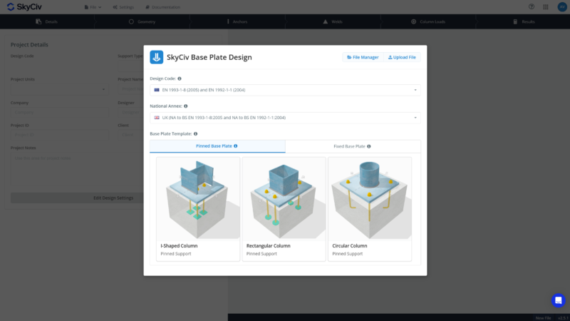
Avvia il software facendo clic Design della piastra di base dal piattaforma o da Qui. Start by selecting a design code, selecting between Pinned and Fixed support, and choosing a starting design template. If designing with Eurocode, also select the National Annex to be used.
You may use the free Base Plate Calculator alongside this documentation as you build your first base plate design.
Scheda Dettagli
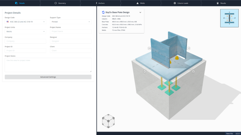
Define project information and configure settings.
- Imposta unità di progetto. AISC can choose between metric and imperial. Other design codes are defaulted to metric. Switching project units will convert all measurements of length, forza, and forces.
- Switch between Pinned and Fixed. Pinned is used for Axial and/or Shear loads only, while Fixed is used for designs with moment loads. È necessario to provide moment load input if using Fixed.
- Immettere i dettagli del progetto: Nome del progetto, Azienda, progettista, ID progetto, Cliente, e note. These details appear in the calculation report and in the detail drawing.
- Configure more settings under Impostazioni avanzate.
- Anche, switching to another design code is available on this tab. It is recommended not to do this half-way through the design as it will reset all progress.
Impostazioni avanzate
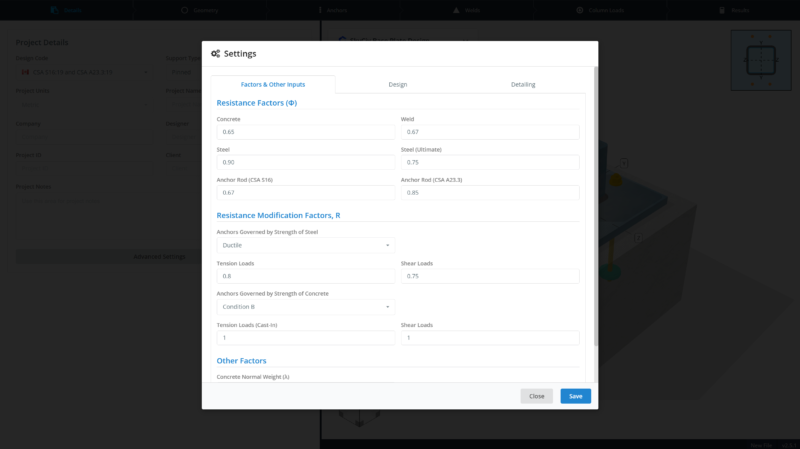
Set settings specific to the project.
- Set Resistance Factors (AISC, CSA), Reduction Factors (AS) or Partial Factors (NEL) nel Fattori & Other Inputs Tab. Also configure additional input values needed in the calculations. The available settings are different for each design code.
- Set assumptions for design in the Design Tab. Changes to these require guidance from a suitably qualified engineer.
- Modify the list of detailing checks to be performed in the Detailing Tab. Most of the checks are optional, except for the design layout check, which determines clashes in the geometries.
Scheda di geometria
Definire la sezione colonna, Dimensioni della piastra di base, e proprietà concrete.
Scheda Colonna
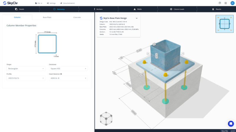
- Modify column shape. Choose among I-shaped sections, Sezioni cave rettangolari, or Circular Hollow Sections.
- Select the correct database. This depends on the available database on the design code. Per esempio, AISC I-shaped sections have W shapes, S shapes, M, shapes and HP shapes.
- Choose your column section. This list is synced with Il Generatore di Sezioni SkyCiv, so it’s complete and reliable.
- Seleziona un materiale dal menu a discesa o inserisci i valori personalizzati (Fy, Fu).
Scheda della piastra di base
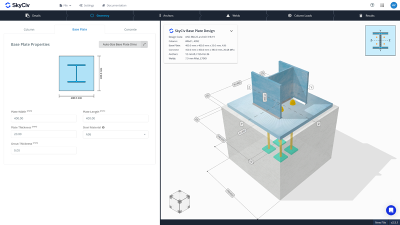
- Set base plate width (dimension across the column profile) e lunghezza (dimension along the column depth).
- Also set base plate thickness. Use thicknesses that are readily available from the manufacturer.
- To add grout, specify thickness. To remove grout, use zero thickness (0). Check your design code for a minimum grout thickness if required.
- Seleziona un materiale dal menu a discesa o inserisci i valori personalizzati (Fy, Fu).
- Uso Dimensione automatica to easily adjust base plate dimensions relative to column dimensions. Nota: Questa funzione non cambia dimensione in base alla forza.
Scheda di cemento
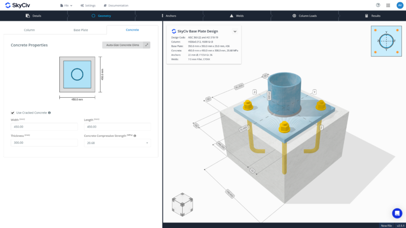
- Specificare il calcestruzzo screpolato o non colpito. To be conservative, use cracked concrete. Some calculations require the use of cracked concrete for the assumptions to be true. Check your design code if you need to use uncracked concrete.
- Imposta dimensioni di cemento (larghezza, lunghezza, spessore).
- Selezionare la resistenza a compressione concreta dal discesa o immettere un valore personalizzato.
- Uso Dimensione automatica to easily adjust concrete dimensions relative to base plate dimensions. Nota: Questa funzione non cambia dimensione in base alla forza.
Scheda Anchors
Seleziona le proprietà di ancoraggio, posizione, e controlli di fallimento.
Scheda Proprietà
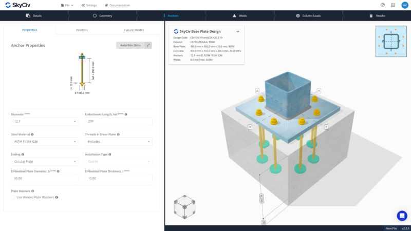
- Choose anchor diameter. Available anchor diameters vary by design code. If the required diameter is not available on the list, request it through SkyCiv Upvoty and provide the relevant specifications.
- Provide embedment length, Avere. To visualize the extents of the embedment length, refer to the 2D figure in the tab.
- Select material grade for the anchor. Custom material grade can also be used by providing Fy and Fu values.
- Definire la forma di fine incorporata: Dritto, piatto, o gancio. Hook is only available in AISC and CSA.
- Set dimensions of the embedded plate. Uso Dimensione automatica to easily adjust dimensions relative to anchor diameter. Nota: Questa funzione non cambia dimensione in base alla forza.
- Installation type is set to Cast-In anchors.
- Other anchor property settings are available depending on the design code. This includes settings to include threads in shear plane (AISC/CSA), to configure hole clearance (NEL), and use of welded washers (AISC/CSA).
Scheda di posizione
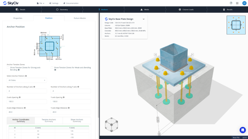
- Select an anchor pattern from the list. This will automatically define a set of anchors relative to given column and base plate sizes. Available anchor patterns are:
- I-shape – Angoli, Solo flangia, Solo Web
- Rettangolare – Angoli, Solo superiore/inferiore, Solo sinistra/destra, Tutti i lati
- Circolare – Angoli
- Adjust the number of anchors, spacing and or edge distances accordingly. If using ‘All Sides’ the number of anchors on each direction can be modified.
- Make use of the 3D renderer at the right or illustrative 2D guide at the top to visualize placement and measurements.
- Abilitare Mostra le zone di tensione di ancoraggio Nelle impostazioni di figura per la guida visiva. Verranno attivati solo le ancore nella zona di tensione per il carico di tensione.
- For Fixed support, enable Show Tension Zones for Strong-axis Bending e Show Tension Zones for Weak-axis Bending to know which locations can activate the anchors for induced uplift. Note that the location of the anchor zones differ per design code.
- Controlla il riepilogo dei dati di ancoraggio per tutte le informazioni sull'ancora - ID ancoraggio, Z and Y coordinates, Indicazione della zona di tensione, and group behavior for anchor checks.
Scheda Modalità di errore
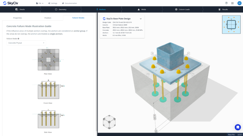
- Selezionare la modalità di errore dal menu a discesa per visualizzare le rappresentazioni grafiche delle modalità di errore del calcestruzzo. Available failure modes are:
- Rottura del calcestruzzo in tensione
- Rottura del calcestruzzo a taglio
- Concrete side face blow-out in tension
- Concrete pryout in shear
- No input is required here. This part is just a helpful guide to review possible anchor failures based on the design and loads.
Scheda di saldature
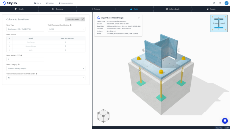
- Scegli il tipo di saldatura: Fillet or CJP/FPBW.
- Set weld material or use custom electrode strength.
- For AISC and CSA, weld size is uniform throughout. For EN and AS, welds on flanges and web can be different.
- Set weld set-back. This is the distance near the fillet radius for I-shaped section where “no weld” is specified. This is helpful when welds clash near the radius, especially on larger weld sizes.
- Additional settings can be placed for AS, specifically on the weld category.
- Compression load transfer is modifiable. Select Yes or No if compression loads will be transferred through welds only. The default is transferring compression loads through bearing and checking the column for bearing capacity. Depending on engineering judgment, transferring through welds may be used instead.
Scheda Carica colonna
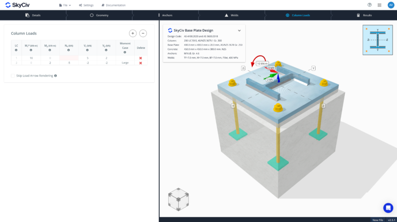
- Enter factored loads.
- For Pinned Supports, provide Axial and/or Shear Loads. For Axial Loads, use positive for compression and negative for tension.
- For Fixed Supports, provide Strong-Axis Moment (uni-axial), Weak-Axis Moment, Axial Load and/or Shear Loads. Note that biaxial bending is not yet supported.
- Utilizzare il + e – buttons to add or remove load combinations.
- Fare clic sulla cella di input di carico per visualizzare la visualizzazione nel rendering 3D.
- When adding multiple load combinations at once, load arrow rendering can be skipped for faster 3D processing.
Scheda Risultati
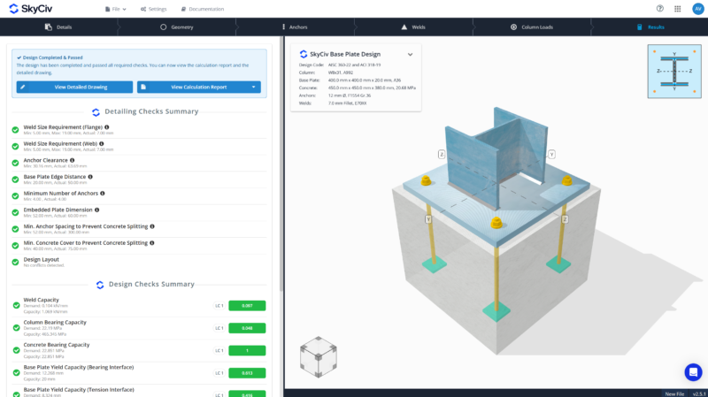
- Clicking results tab will automatically run the calculation process.
- View pass and fail results at a glance.
- La DETTAGLIO Riepilogo Controllo provides a comprehensive review of minimum and maximum dimension compliance and conflicts detection in the design.
- La Controlli di progettazione provides a color-coded pass or fail, with the utilization ratio included. The governing load combination that resulted to the highest ratio per design check is also provided.
- Try the free tool. Non è richiesta la registrazione.
Rapporto di calcolo
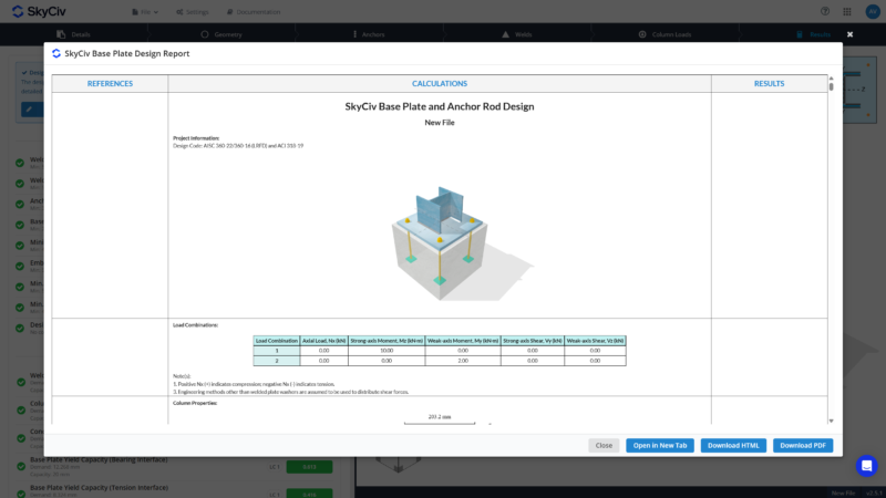
- Three calculation report options are available:
- Rapporto completo – Provides comprehensive project details, step-by-step calculations, immagini, and diagrams.
- Lite Report – Provides project details and step-by-step calculations without images or diagrams.
- Relazione di sintesi – Provides project details and final results only.
Detail Drawing
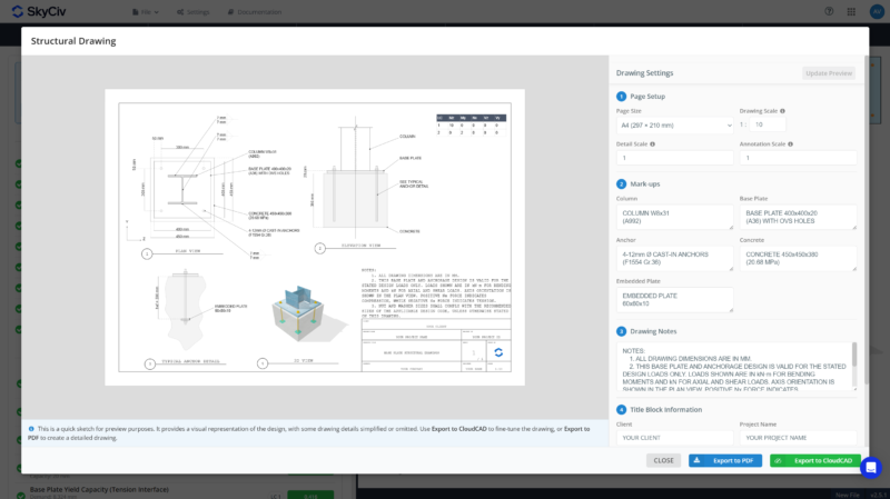
- Page size is automatically determined based on the actual size of the column, utilizza combinazioni di carico fattorizzate in ASCE, e concreto. Page size can still be modified
- Set the scales:
- Drawing scale – adjusts how the whole drawing printed on paper
- Detail scale – adjusts the size of the objects as a group
- Annotation scale – adjust the size of the dimensions, mark-ups texts, and other labels
- Input key information for the mark-ups: Colonna, Piastra di base, Ancorare, Concrete and Embedment Plate (se presente)
- Customize the drawing notes. Provide as much note as needed.
- Supply title block information, if not the same as the information from the project details.
Esporta in PDF
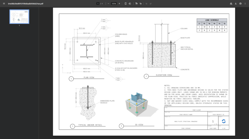
- Export the default drawing shown in the preview as PDF.
- No additional payment required for existing base plate subscriber. Only uses 2 API credits to generate a drawing.
- Drawing generation may take time.
Export to CloudCAD
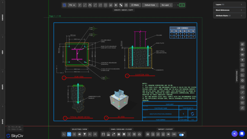
- Export the drawing to CloudCAD. No need to draw anything by hand.
- Easily modify and adjust the details for further enhancement and customization.
- Explore CloudCAD from Qui.
Prova lo strumento gratuito
L'impostazione del tuo primo modello di piastra di base richiede meno di 10 minuti. Prova il Calcolatore di design della piastra di base Skyciv. Gratuito da usare, straight from the browser.
