
La Tagli della sezione della piastra tool lets you extract forces, momenti, and other plate results across slabs, piatti, o muri. It works in two modes: Taglio, which reads results along a single line, e Striscia, which integrates results over a defined width. Ciò è utile per la progettazione di strisce di solai, verifica del comportamento locale delle piastre, e verifica della distribuzione del carico.
Come utilizzare lo strumento Tagli sezione piastra
Dopo aver risolto, dovresti sentirti pronto per affrontare progetti molto più grandi e complessi Piatti poi Tagli della sezione della piastra nel pannello di sinistra.
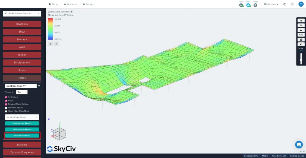
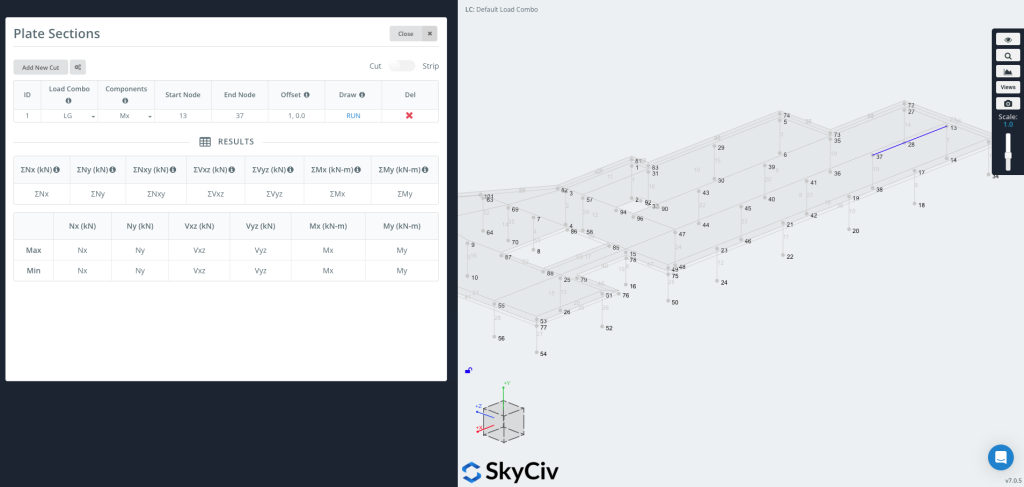
Clic "Aggiungi nuovo taglio" per creare una nuova voce.
Ogni taglio include:
- Carica combinato – Selezionare da quale combinazione di carico estrarre i risultati.
- Componenti – Scegli il tipo di risultato. The available components depend on the active mode (Cut or Strip) – see the sections below.
- Avvia Node / End Node – Definire il segmento in cui verrà posizionato il taglio. You can also enter coordinates directly, per esempio.
[0,0,0]. - Compensare – Optionally shift the cut line. Enter it as
a,b, dove un carico is the node ID that sets the offset direction and b is the offset distance (per esempio.1, 0.5).- Ciò è utile quando si desidera un grafico con un offset impostato da un bordo senza calcolare manualmente le coordinate.
Utilizzare il Taglio / Striscia toggle in the top right corner to switch between the two modes. They differ in what they extract and which components are available.
Ora puoi disegnare & Esegui il taglio
stampa CORRERE per generare il taglio. La linea di taglio apparirà sul tuo modello (come mostrato sul lato destro dell'immagine), che per il tabella dei risultati verrà popolato con i valori massimo e minimo per ciascun componente selezionato.
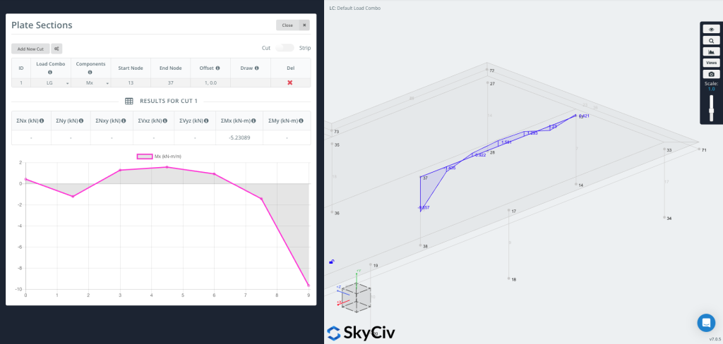
Ora puoi tracciare il grafico direttamente sulla geometria, mostrando visivamente i valori dei risultati lungo la linea di taglio.
Cut Mode – Results Along a Line
Nel Taglio mode the tool reads plate results along the cut line and reports them per unit length, together with the summed (Σ) total along the whole cut.
- Componenti – Nx, IL, Nxy, Vxz, Vyz, Mx, Mio (o Tutto at once), the Wood-Armer design moments (M1 / Eurocodice di design con piastra di base in acciaio, Superiore / Parte inferiore), and Soil Pressure.
- Assi – Results are reported in each plate’s local axes.
- unità – Force or moment per unit length for the diagram; the results table shows the totals ΣNx … ΣMy along the cut.
Strip Mode – Results Over a Width
Turn on the Striscia toggle in the top right corner to generate a strip section.
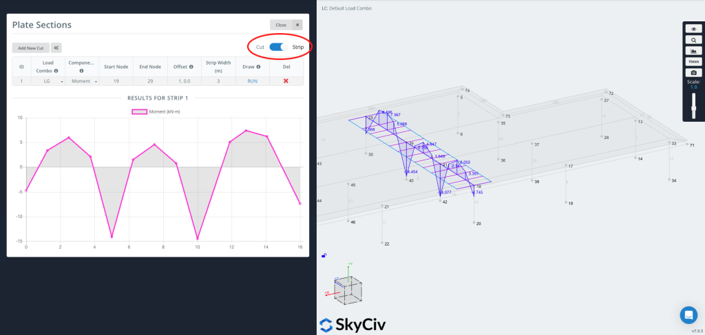
A Striscia estrae i risultati su una larghezza, not just along a line. At each station along the cut it integrates the plate results across the strip width, so the reported value is the total force or moment carried by that slice of slab. This is typically used for disegno della striscia della lastra, where design codes work with forces and moments over a strip of slab rather than at a single point.
Strip axis convention
A strip has a longitudinal axis running from the start node to the end node, and it is treated as an equivalent trave along that axis. All plate results are first transformed into this axis and then integrated across the strip width: the bending moment is reported about the strip axis, just as you would read the bending moment of a beam running along it, and the axial, shear and in-plane shear forces are resolved and summed the same way. In breve, the distributed plate forces are reduced to the resultant forces and moments that an equivalent beam of that width would carry.
Una striscia è utile quando serve:
- Valori di progetto per strisce di soletta unidirezionali o bidirezionali
- Valori più rappresentativi su una striscia fisica anziché su una singola linea
- Code-based averaging of peak values (see Peak Moment Ratio below)
Strip-specific inputs
- Strip Width – Enter
Wl,Wrfor an asymmetric strip, dove Wl is the width to the left and Wr the width to the right (viewed from start to end). Enter a single value for a symmetric strip. - Componenti – Moment, cesoia, Assiale, In-plane Shear, e M comb top / M comb bot (combined reinforcement design moments – see below).
- Peak Moment Ratio (opzionale) – Enable this option in the settings to cap the peaks of the diagram and distribute the moment more evenly across the strip, as required by code-based averaging such as the CSA two-thirds rule. Enter a ratio between 0 e 1 (1.0 = no capping).
M comb top / M comb bot (combined design moments)
The “M comb” components are the combined Wood-Armer design moments. At every point a plate carries two bending moments and a twisting moment Mxy. Reinforcement bars resist bending along their own direction but not twist, so the twisting moment has to be folded into the bending moments – the Wood-Armer method does this, giving a single equivalent design moment for each reinforcement layer.
Superiore e parte inferiore refer to the two reinforcement layers (the two faces of the plate), and they are defined by the local z-axis of each finite element’s coordinate system: the face the local +z axis points toward is the superiore, and the opposite face is the parte inferiore. Because the local axes are assigned per element – and depend on how each element is defined and the order of its nodes – check the element local axes in the model to confirm which physical face is top and which is bottom. M comb top sizes the reinforcement near the top face, e M comb bot the reinforcement near the bottom face.
Because the results are integrated across the width, Strip values are reported in force or moment units (not per unit length).
Cut vs Strip – Which to Use
- Uso Taglio for a quick diagram of a result component along a line (in plate axes), or to get the total (Σ) across the cut.
- Uso Striscia when you need design forces and moments over a finite width (disegno della striscia della lastra), combined reinforcement moments (M comb), or code-based peak averaging.
