ΣΦΑΙΡΙΚΗ ΕΙΚΟΝΑ
ΣΕ 1993-1-1: Σχεδιασμός μεταλλικών κατασκευών (Ευρωκώδικας 3) περιγράφει κατευθυντήριες γραμμές σχεδιασμού για δομικά μέλη από χάλυβα για χρήση σε κτίρια χρησιμοποιώντας τη μέθοδο οριακής κατάστασης. Ο σχεδιασμός οριακής κατάστασης συνεπάγεται σύγκριση των συντελεστών φορτίων σχεδιασμού με μειωμένη χωρητικότητα διατομής και μελών. Αυτοί οι παράγοντες προορίζονται να λάβουν υπόψη τη μεταβλητότητα στις συνθήκες φόρτωσης και στις ιδιότητες του υλικού. Για την τελική οριακή κατάσταση (ULS) σχεδιασμός για να είναι ικανοποιημένος, η παρακάτω σχέση πρέπει να είναι αληθινή:
\(ULS \;Παράγοντας * Φορτίο ≤ Μείωση \;Παράγοντας * Ικανότητα)
Αυτός ο οδηγός σχεδιασμού περιγράφει τη διαδικασία σχεδιασμού ενός δομικού χαλύβδινου μέλους σύμφωνα με το EN 1993-1-1 SkyCiv Renderer API ΣΕ 1993-1-1 Σχεδιασμός μελών χάλυβα μονάδα μέτρησης.
Παρακολουθήστε τον Ευρωκώδικά μας 3 Επίδειξη του Steel Design
Περιεχόμενα
Ιδιότητες υλικού
Κατασκεύασμα
ΣΕ 1993-1-1 παρέχει οδηγίες σχεδιασμού για τέσσερις τύπους κατασκευής δομικού χάλυβα:
- Τμήματα θερμής έλασης: Οι τομές θερμής έλασης κατασκευάζονται με θέρμανση και έλαση χάλυβα μπιγιέτα μέσω ενός μύλου για να επιτευχθεί το απαιτούμενο σχήμα. Στα παραδείγματα περιλαμβάνονται οι ενότητες UB/UC/UBP I, Τομές Τ, Τμήματα καναλιών και γωνιών.
- Συγκολλημένα Τμήματα: Συγκολλημένος (ή κατασκευασμένα) τα τμήματα αποτελούνται από πολλές επίπεδες πλάκες θερμής έλασης συγκολλημένες μεταξύ τους κατά μήκος για να σχηματίσουν ένα σχήμα χάλυβα. Τα προσαρμοσμένα κατασκευασμένα τμήματα συνήθως συγκολλούνται.
- Ενότητες Θερμα Φινιρισμένων: Τα θερμά τελειωμένα τμήματα παράγονται με θέρμανση του χάλυβα πέρα από τη θερμοκρασία ανακρυστάλλωσής του πριν από την έλαση για τη βελτίωση της αντοχής του τελικού προϊόντος. Αυτά τα τμήματα είναι σχεδόν πάντα δομικά κοίλα τμήματα (RHS/SHS/CHS).
- Ψυχρά Σχηματισμένα Τμήματα: Τα ψυχρά διαμορφωμένα τμήματα κατασκευάζονται με πίεση του χαλύβδινου μπιγιέτας μέσω ενός μύλου σε θερμοκρασία δωματίου. Η ψυχρή διαμόρφωση μπορεί να χρησιμοποιηθεί για την παραγωγή δομικών κοίλων τμημάτων και λεπτότερων ανοιχτών τμημάτων. Σημείωση ΕΝ 1993-1-1 παρέχει μόνο καθοδήγηση για κοίλα ψυχρά τμήματα.
Βαθμός χάλυβα
Η Ευρώπη και το Ηνωμένο Βασίλειο έχουν πολλές ποιότητες χάλυβα (δυνάμεις) που μπορεί να χρησιμοποιηθεί για σχεδιασμό σύμφωνα με το EN 1993-1-1. Υπάρχουν πολλά ευρωπαϊκά πρότυπα υλικών για διαφορετικούς τύπους κατασκευής χάλυβα:
- ΣΕ 10025: Προϊόντα θερμής έλασης.
- ΣΕ 100210: Δομικά κοίλα τμήματα θερμής φινιρίσματος.
- ΣΕ 10219: Εν ψυχρώ διαμορφωμένα συγκολλημένα δομικά κοίλα τμήματα.
Τμήματα θερμής έλασης (ΣΕ 10025)
Οι κοινές διαθεσιμότητες ποιότητας και οι ενδεικτικές αντοχές διαρροής για σχήματα χάλυβα θερμής έλασης περιγράφονται παρακάτω:
Ελάχιστη ισχύς απόδοσης (MPa) |
|||||||||
|---|---|---|---|---|---|---|---|---|---|
| Βαθμός | ≤16mm | 16-40χιλ | 40-63χιλ | 63-80χιλ | 80-100χιλ | 100-150χιλ | 150-200χιλ | 200-250χιλ | 250-400χιλ |
| μικρό 235 | 235 | 225 | 215 | 215 | 215 | 195 | 185 | 175 | 165 |
| μικρό 275 | 275 | 265 | 255 | 245 | 235 | 225 | 215 | 205 | 195 |
| μικρό 355 | 355 | 345 | 335 | 325 | 315 | 295 | 285 | 275 | 265 |
| μικρό 460 | 460 | 440 | 420 | 400 | 390 | 390 | – | – | – |
Ελάχιστη αντοχή εφελκυσμού (MPa) |
||||||
|---|---|---|---|---|---|---|
| Βαθμός | ≤3mm | 3-100χιλ | 100-150χιλ | 150-250χιλ | 250-400χιλ | |
| μικρό 235 | 360 | 350 | 350 | 340 | 330 | |
| μικρό 275 | 430 | 410 | 400 | 380 | 380 | |
| μικρό 355 | 510 | 470 | 450 | 450 | 450 | |
| μικρό 460 | – | 550 | 530 | – | – | |
Δομικές κοίλες τομές θερμής φινιρίσματος (ΣΕ 100210)
Οι κοινές διαθεσιμότητες ποιότητας και οι ενδεικτικές αντοχές διαρροής για δομικές κοίλες τομές θερμής φινιρίσματος περιγράφονται παρακάτω:
Ελάχιστη ισχύς απόδοσης (MPa) |
||||||
|---|---|---|---|---|---|---|
| Βαθμός | ≤16mm | 16-40χιλ | 40-63χιλ | 63-80χιλ | 80-100χιλ | 100-120χιλ |
| μικρό 235 Η | 235 | 225 | 215 | 215 | 215 | 195 |
| μικρό 275 Η | 275 | 265 | 255 | 245 | 235 | 225 |
| μικρό 355 Η | 355 | 345 | 335 | 325 | 315 | 295 |
Ελάχιστη αντοχή εφελκυσμού (MPa) |
|||
|---|---|---|---|
| Βαθμός | ≤3mm | 3-100χιλ | 100-120χιλ |
| μικρό 235 Η | 360 | 360 | 350 |
| μικρό 275 Η | 430 | 410 | 400 |
| μικρό 355 Η | 510 | 470 | 450 |
Απόδοση παραγωγής & Αντοχή εφελκυσμού
Η αντοχή διαρροής ενός υλικού είναι το όριο τάσης πέρα από το οποίο θα συμβεί πλαστική παραμόρφωση. Η αντοχή σε εφελκυσμό είναι η μέγιστη τάση που μπορεί να υποστεί ένα υλικό πριν αστοχήσει / διασπάται. Οι αντοχές διαρροής και εφελκυσμού των τμημάτων χάλυβα εξαρτώνται από την ποιότητα και το πάχος του χάλυβα. Συνήθως η αντοχή αυξάνεται με την ποιότητα χάλυβα αλλά μειώνεται με το αυξημένο πάχος του χάλυβα.
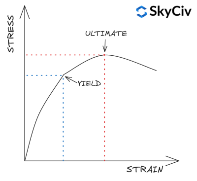
ΣΕ 1993-1-1 Τραπέζι 3.1 παρέχει μια απλοποιημένη προσέγγιση για τον υπολογισμό της διαρροής και της αντοχής σε εφελκυσμό μιας τομής με βάση την ποιότητα και το πάχος της. Ένας πιο λεπτομερής υπολογισμός αντοχής υλικού μπορεί να πραγματοποιηθεί ανατρέχοντας στο σχετικό πρότυπο υλικού. Το SkyCiv EN 1993-1-1 Η ενότητα Steel Member Design κάνει δεν χρησιμοποιήστε αυτήν την απλοποίηση και αντ' αυτού αναφέρεται στα σχετικά πρότυπα υλικών για τον υπολογισμό της αντοχής του υλικού.
Επιλογή ενότητας στο SkyCiv EN 1993-1-1 Σχεδιασμός μελών χάλυβα
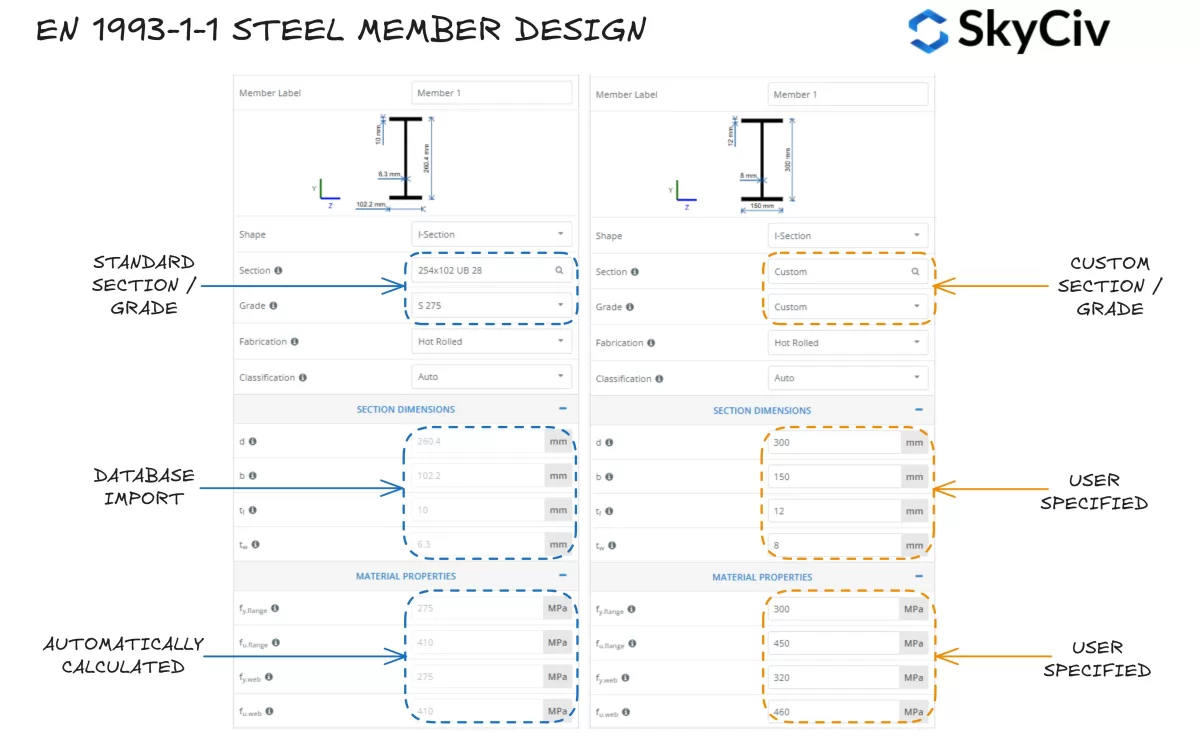
Το SkyCiv ΣΕ 1993-1-1 Σχεδιασμός μελών χάλυβα Το εργαλείο επιτρέπει στους χρήστες να επιλέξουν ένα τυπικό τμήμα χάλυβα από τη βάση δεδομένων SkyCiv ή να σχεδιάσουν ένα εντελώς προσαρμοσμένο τμήμα. Το πρόγραμμα υπολογίζει αυτόματα τις τιμές αντοχής διαρροής για τη φλάντζα τομής και τον ιστό με βάση την επιλεγμένη ποιότητα χάλυβα. Οι χρήστες μπορούν επίσης να υιοθετήσουν μια προσαρμοσμένη ποιότητα χάλυβα και να εισάγουν χειροκίνητα τις ιδιότητες του υλικού, εάν απαιτείται.
Ταξινόμηση Ενοτήτων
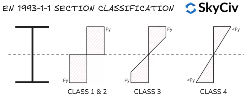
Το Section Classification είναι ένα σύστημα που χρησιμοποιείται από το EN 1993-1-1 να προσδιορίσει την ευαισθησία ενός τμήματος σε τοπικό λυγισμό πριν αποκτήσει την πλήρη πλαστική του χωρητικότητα. Τα μεγάλα λεπτά σχήματα είναι συνήθως πιο ευαίσθητα στον τοπικό λυγισμό παρά στα μικρά, στιβαρά σχήματα. Το SkyCiv ΣΕ 1993-1-1 Σχεδιασμός μελών χάλυβα Το εργαλείο υπολογίζει αυτόματα την ταξινόμηση τυπικών και προσαρμοσμένων χαλύβδινων τμημάτων με βάση τις εφαρμοζόμενες συνθήκες φόρτωσης. Ευρωκώδικας 3 έχει τέσσερις κατηγορίες Ταξινόμησης Ενοτήτων:
- Τάξη 1: Τομές που μπορούν να σχηματίσουν μια πλαστική άρθρωση και να αναπτύξουν την πλαστική ροπή/αξονική τους αντίσταση, που σημαίνει ότι ολόκληρο το τμήμα μπορεί να φτάσει την αντοχή διαρροής υπό κάμψη και/ή συμπίεση. Τάξη 1 Τα τμήματα έχουν επίσης υψηλή περιστροφική ικανότητα. Οι ιδιότητες πλαστικής διατομής χρησιμοποιούνται στους υπολογισμούς χωρητικότητας.
- Τάξη 2: Τμήματα με δυνατότητα σχηματισμού πλαστικού μεντεσέ αλλά έχουν περιορισμένη περιστροφική ικανότητα. Ευρωκώδικας 3 μεταχειρίζεται Τάξη 1 και Τάξη 2 τμήματα ομοίως για όλους σχεδόν τους υπολογισμούς χωρητικότητας.
- Τάξη 3: Τομές που μπορούν να επιτύχουν αντοχή διαρροής στην εξαιρετικά συμπιεστική ίνα τους, αλλά κουμπώστε τοπικά πριν επιτευχθεί αντίσταση πλαστικής ροπής. Οι ιδιότητες ελαστικής διατομής χρησιμοποιούνται στους υπολογισμούς χωρητικότητας.
- Τάξη 4: Τοπικός λυγισμός θα συμβεί πριν επιτευχθεί η αντοχή διαρροής σε τμήμα/τα του τμήματος. Οι ιδιότητες μειωμένης ελαστικής διατομής χρησιμοποιούνται στους υπολογισμούς χωρητικότητας.
Σημείωση, Τάξη 4 οι ενότητες περιλαμβάνουν πρόσθετη πολυπλοκότητα στον υπολογισμό των ιδιοτήτων του τμήματος / αντίσταση και δεν καλύπτονται σε αυτόν τον οδηγό.
Στοιχεία Συμπίεσης
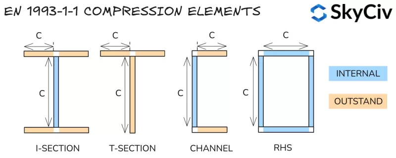
Η ταξινόμηση τμημάτων καθορίζεται με το σπάσιμο ενός τμήματος σε μια σειρά από στοιχεία συμπίεσης και τον υπολογισμό της λεπτότητας τους (καθαρό μήκος σε σχέση με το πάχος). Τα στοιχεία ταξινομούνται ως είτε:
- Εσωτερικός: Συγκρατείται από λυγισμό και στα δύο άκρα – δηλ. ιστού ενός I-Section.
- Εξαιρετικό: Συγκρατείται μόνο από λυγισμό στο ένα άκρο – δηλ. φλάντζα ενός I-Section.
Οι υπολογισμένες τιμές λεπτότητας συγκρίνονται με τον Πίνακα 5.2 στην ΕΝ 1993-1-1 να καθορίσουν την τάξη τους. Η ταξινόμηση του τμήματος λαμβάνεται ως η λιγότερο ευνοϊκή ταξινόμηση των στοιχείων συμπίεσης του. Σημείωση, η ταξινόμηση του τμήματος αλλάζει ανάλογα με τις δυνάμεις στο τμήμα (ιδιαίτερα μεταβαλλόμενη αξονική δύναμη). Οι μέθοδοι για την ταξινόμηση κάθε τύπου φόρτωσης συνοψίζονται παρακάτω.
Αναλογίες ταξινόμησης
Εξαρτήματα που υπόκεινται σε συμπίεση
Τα στοιχεία σε καθαρή συμπίεση ταξινομούνται με βάση τη λεπτότητά τους μόνο χρησιμοποιώντας τα όρια που περιγράφονται παρακάτω.
| Τάξη | Εσωτερικά μέρη | Εξαιρετικά ανταλλακτικά | |
| 1 | ντο / t ≤ 33ε | ντο / t ≤ 9ε | |
| 2 | ντο / t ≤ 38ε | ντο / t ≤ 10ε | |
| 3 | ντο / t ≤ 42ε | ντο / t ≤ 14ε | |
Οπου:
\(ε = sqrt{\frac{235}{f_y}}\)
Μέρη που υπόκεινται σε κάμψη
Τα εσωτερικά στοιχεία σε καθαρή κάμψη ταξινομούνται με βάση τη λεπτότητά τους στα όρια που περιγράφονται παρακάτω.
| Τάξη | Εσωτερικά μέρη | |
| 1 | ντο / t ≤ 72ε | |
| 2 | ντο / t ≤ 83ε | |
| 3 | ντο / t ≤ 124ε | |
Τα εξαιρετικά στοιχεία που υπόκεινται σε καθαρή κάμψη ταξινομούνται με βάση την αναλογία θλιπτικής και εφελκυστικής τάσης κάτω από την τιμή της ροπής κάμψης που οδηγεί σε θλιπτική τάση ίση με την τάση διαρροής στην ακραία ίνα. Η μέθοδος για τον υπολογισμό αυτής της αναλογίας περιγράφεται λεπτομερώς στην παρακάτω ενότητα.
Εξαρτήματα που υπόκεινται σε συμπίεση & Κάμψη
Τα στοιχεία που υπόκεινται σε συνδυασμένη συμπίεση και κάμψη ταξινομούνται με βάση τη συμπίεσή τους / κατανομή εφελκυστικής τάσης υπό την εφαρμοζόμενη φόρτιση συμπίεσης. Αυτή η αναλογία αντιπροσωπεύεται από το σύμβολο α για την κατανομή της πλαστικής τάσης και το σύμβολο ψ για την κατανομή ελαστικής τάσης.
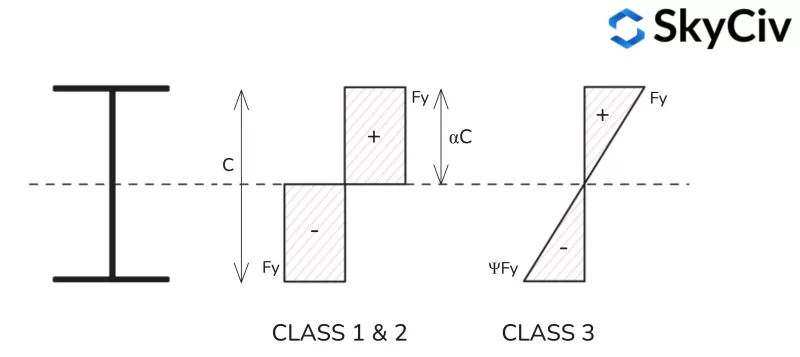
Κατανομή Πλαστικής Τάσης
Τύποι για τον υπολογισμό του λόγου πλαστικών τάσεων (α) για διαφορετικά προφίλ σχήματος παρέχονται παρακάτω.
Κατανομή πλαστικών τάσεων I-Section

Κατανομή πλαστικών καταπονήσεων του τμήματος T
Σημειώστε ότι οι μικροκατανομές τάσεων άξονα για τις διατομές Τ είναι παρόμοιες με αυτές μιας διατομής Ι.

Κατανομή τάσεων από πλαστικό τμήμα καναλιού
Σημειώστε ότι οι κατανομές τάσεων του κύριου άξονα για τις τομές Τ είναι παρόμοιες με αυτές μιας διατομής Ι.

RHS Plastic Stress Distribution

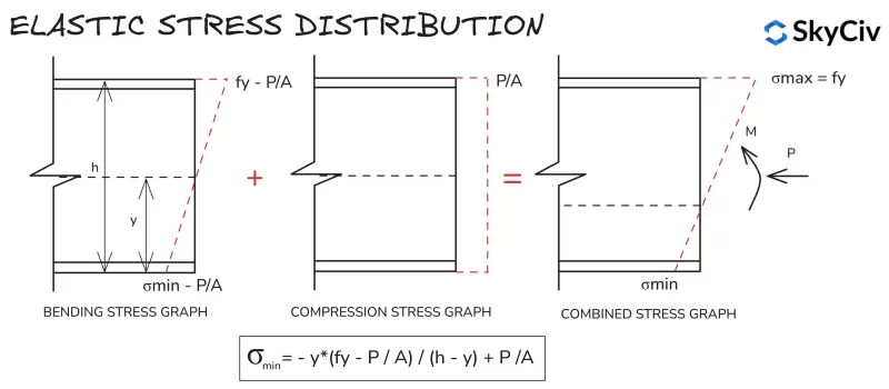
Ελαστική Κατανομή Τάσης
Οι υπολογισμοί κατανομής ελαστικής τάσης είναι παρόμοιοι για όλα τα τμήματα και τα σχήματα, λόγω της γραμμικής κατανομής τάσεων μεταξύ των ακραίων ινών. Ο τύπος για τον υπολογισμό της ελάχιστης τάσης σε ένα τμήμα υπό εφαρμοζόμενη συμπίεση και κάμψη φαίνεται παρακάτω.
Ενότητα Ταξινόμηση στο SkyCiv EN 1993-1-1 Σχεδιασμός μελών χάλυβα
ο SkyCiv ONE 1993-1-1 Σχεδιασμός μελών χάλυβα Το εργαλείο καθορίζει αυτόματα την Ταξινόμηση Ενοτήτων των τυπικών και προσαρμοσμένων ενοτήτων με βάση τη φόρτωση εισόδου από τον χρήστη. Παράδειγμα εξόδου για βαθμό S 275, 430Το κανάλι x100x64 με φόρτιση συμπίεσης 20 kN περιγράφεται αναλυτικά παρακάτω.
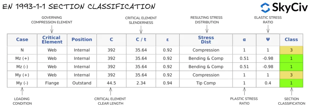
Μια ενιαία τιμή ταξινόμησης διατομής χρησιμοποιείται για όλους τους υπολογισμούς με βάση την εφαρμοζόμενη αξονική δύναμη και την κατεύθυνση της εφαρμοζόμενης ροπής κάμψης. Εάν σε ένα μέλος εφαρμόζεται ροπή κάμψης και στους δύο άξονες, υιοθετείται η πιο συντηρητική ταξινόμηση από κάθε κατεύθυνση. Οι χρήστες μπορούν επίσης να παρακάμψουν τον αυτόματο υπολογισμό της Ταξινόμησης Ενοτήτων και να καθορίσουν μια ταξινόμηση με μη αυτόματο τρόπο.
Σημείωση, Ρήτρα 5.4.1(3) καθορίζει ότι μεμονωμένα συμμετρικά τμήματα (όπως τα τμήματα T και τα κανάλια) δεν μπορούν να σχεδιαστούν χρησιμοποιώντας πλαστική ανάλυση όταν κάμπτονται γύρω από τον μη συμμετρικό άξονά τους. Ως εκ τούτου, τμήματα αυτής της φύσης εκχωρούνται αυτόματα Κλάση 3.
Τομή Αντίσταση
Κάμψη
Αντίσταση κάμψης τμήματος
Η χωρητικότητα της ροπής κάμψης διατομής υπολογίζεται χρησιμοποιώντας το EN 1993-1-1 Ρήτρα 6.2.5.
\(Μ_{ντο,Rd} = W*f_y/γ_{Μ0}\)
Όπου W είναι ο συντελεστής πλαστικής διατομής (Δπαρακαλώ) για την Τάξη 1 & 2 τμήματα, ή το μέτρο ελαστικής διατομής (Δο) για την Τάξη 3 τμήματα, φάκαι είναι η τάση διαρροής του υλικού και γ είναι ο μερικός συντελεστής μείωσης ασφάλειας.
Ο συντελεστής τομής ενός σχήματος είναι μια γεωμετρική ιδιότητα που ποσοτικοποιεί την αντίσταση κάμψης ενός σχήματος. Ο συντελεστής πλαστικής διατομής υποθέτει ότι ολόκληρο το τμήμα φθάνει την αντοχή διαρροής υπό κάμψη. Ο συντελεστής πλαστικής διατομής μιας τομής υπολογίζεται ως εξής:
\(cdot K_a{παρακαλώ} = Α_{ντο} * y_{ντο} + ΕΝΑ_{Τ} * y_{Τ} \)
Όπου ο Αντο και ΑΤ είναι οι περιοχές εκατέρωθεν του Πλαστικού Ουδέτερου Άξονα (PNA), και γντο / καιτ είναι η απόσταση από το PNA στο κέντρο αυτών των περιοχών. Σημείωση, η θέση PNA είναι ίση με τη γεωμετρική κεντροειδή θέση για συμμετρικά σχήματα αλλά θα δεν ισούται με τη γεωμετρική κεντροειδή θέση για ασύμμετρα σχήματα.
Ο συντελεστής ελαστικής διατομής λαμβάνει ολόκληρο το τμήμα (σχήμα) παραμένει ελαστικό υπό κάμψη, δηλ. κανένα τμήμα του τμήματος δεν υπερβαίνει την αντοχή διαρροής (φάκαι) του υλικού. Ο συντελεστής ελαστικής διατομής μιας διατομής υπολογίζεται ως εξής:
\(cdot K_a{ο} = frac{Εγώ}{και}\)
Όπου I είναι η δεύτερη ροπή του εμβαδού και y το γεωμετρικό κέντρο του σχήματος. Σημείωση για ασύμμετρο σχήμα, η τιμή του συντελεστή ελαστικότητας που χρησιμοποιείται στο σχεδιασμό είναι η μικρότερη τιμή για θετική και αρνητική κάμψη γύρω από αυτόν τον άξονα.
Υπολογισμός της αντίστασης κάμψης διατομής στο SkyCiv EN 1993-1-1 Σχεδιασμός μελών χάλυβα
Αφού υπολογιστεί η σχετική Ταξινόμηση Ενοτήτων, η μονάδα υπολογίζει την ικανότητα ροπής κάμψης τομής (Mc) για κάθε κύριο άξονα. Τα αποτελέσματα για το ίδιο κανάλι 430x100x64 φαίνονται στο παρακάτω παράδειγμα.

Κουρεύω
Διατμητική αντίσταση τομής
Η διατμητική αντίσταση υπολογίζεται χρησιμοποιώντας το EN 1993-1-1 Ρήτρα 6.2.6. Οι υπολογισμοί χωρητικότητας εξαρτώνται από την Ταξινόμηση Τμήματος του χαλύβδινου μέλους. Χωρητικότητα για Τάξη 1 & 2 Οι τομές υπολογίζονται με βάση την αντίσταση πλαστικής διάτμησης, ενώ χρησιμοποιείται ελαστική αντίσταση διάτμησης για την Κλάση 3 & 4 τμήματα.
Η αντίσταση πλαστικής διάτμησης υπολογίζεται χρησιμοποιώντας τον παρακάτω τύπο:
\(V_{παρακαλώ,Rd}=A_v * (f_y / \τ.μ.{3}) / γ_{Μ0}\)
Όπου Av είναι το εμβαδόν διάτμησης της τομής προς την κατεύθυνση της εφαρμοζόμενης διατμητικής δύναμης. Για τα περισσότερα τμήματα αυτή η περιοχή είναι ισοδύναμη με την περιοχή του ιστού για διάτμηση κατεύθυνσης κύριου άξονα, και την περιοχή των φλαντζών για την άλλη κατεύθυνση. Οι τύποι για τον υπολογισμό του εμβαδού διάτμησης παρέχονται στο EN 1993-1-1 Ρήτρα 6.2.6(3).
Η ελαστική αντίσταση διάτμησης υπολογίζεται χρησιμοποιώντας την παρακάτω σχέση, που εξασφαλίζει ότι η διατμητική τάση στο κρίσιμο σημείο της διατομής είναι μικρότερη από την τάση διαρροής.
\(τ_{Εκδ}/(f_y / (\τ.μ.{3 * γ_{Μ0}})) ≤ 1\)
Η διατμητική τάση σε αυτό το κρίσιμο σημείο υπολογίζεται ως εξής:
\(τ_{Εκδ}=(V_{Εκδ} * μικρό)/(Εγώ * τ)\)
Όπου ο VΕκδ είναι η εφαρμοζόμενη διατμητική δύναμη, S είναι η πρώτη στιγμή της περιοχής, I είναι η ροπή τομής του εμβαδού και t είναι το πάχος στην κρίσιμη θέση τάσης.
Ο τύπος ελαστικής διατμητικής τάσης μπορεί στη συνέχεια να διευθετηθεί ώστε να αντιπροσωπεύει μια τιμή αντίστασης (σε kN):
\(V_{ο,Rd} = (Εγώ * τ * \τ.μ.{3})/(μικρό * f_y)\)
Λυγισμός διάτμησης
Μακρύς, Οι λεπτοί ιστοί ενδέχεται να λυγίσουν υπό την εφαρμοζόμενη διατμητική δύναμη προτού φτάσουν στην ελαστική τους αντίσταση διάτμησης. Οι ιστοί είναι ευαίσθητοι σε λυγισμό διάτμησης εάν ικανοποιούν τον παρακάτω τύπο από το EN 1993-1-1 Ρήτρα 6.2.6(6):
\(η / τ > 72 * ε/η \)
Οπου το η είναι ένας παράγοντας που συνήθως λαμβάνεται ως 1.0. Οι ιστοί που είναι επιρρεπείς σε λυγισμό διάτμησης πρέπει να ελέγχονται σύμφωνα με την Ενότητα 5 ή ΚΑΙ 1993-1-5. Σημείωση, διατμητική ικανότητα σύμφωνα με το ΕΝ 1993-1-5 δεν καλύπτεται από το SkyCiv EN 1993-1-1 εργαλείο, αλλά θα εμφανιστεί μια προειδοποίηση εάν ένα τμήμα είναι επιρρεπές σε λυγισμό διάτμησης.
Επίδραση της διατμητικής δύναμης στην κάμψη & Αντίσταση στη συμπίεση
Η υψηλή εφαρμοζόμενη διατμητική δύναμη μπορεί να έχει αρνητικό αντίκτυπο στη ροπή και την αξονική αντίσταση μιας διατομής. Στο ΕΝ 1993-1-1, αυτή η κρούση αποτυπώνεται με τη μείωση της αντοχής διαρροής της τομής σε σχέση με το μέγεθος της εφαρμοζόμενης διάτμησης (ανατρέξτε στη ρήτρα 6.2.8 & 6.2.10). Όταν η διατμητική δύναμη διατομής είναι λιγότερο από το ήμισυ της πλαστικής του αντίστασης διάτμησης προς αυτή την κατεύθυνση, αυτός ο αντίκτυπος μπορεί να αγνοηθεί. Εάν η εφαρμοζόμενη διάτμηση είναι μεγαλύτερη από αυτή την τιμή, η μειωμένη ισχύς διαρροής υπολογίζεται ως εξής:
\(φά_{και,Rd} = (1 -ρ) * f_y \)
Οπου:
\(ρ = (2 * V_{Εκδ} / V_{παρακαλώ,Rd} – 1)^2)
ο SkyCiv ONE 1993-1-1 Σχεδιασμός μελών χάλυβα Η μονάδα υπολογίζει αυτόματα οποιαδήποτε μείωση της αντοχής διαρροής λόγω υψηλής εφαρμοζόμενης διατμητικής δύναμης και χρησιμοποιεί αυτή τη μειωμένη τιμή στους υπολογισμούς της κάμψης και της αντίστασης θλίψης. Σημείωση, Αυτή η μείωση ισχύει μόνο για την αντίσταση διατομής ενός μέλους, όχι την αντίσταση λυγισμού.
Υπολογισμός διατμητικής αντίστασης στο SkyCiv EN 1993-1-1 Σχεδιασμός μελών χάλυβα
ο SkyCiv ONE 1993-1-1 Σχεδιασμός μελών χάλυβα Το εργαλείο υπολογίζει τη διατμητική ικανότητα μιας τομής και στις δύο κατευθύνσεις του κύριου άξονα. Αποτελέσματα από τους υπολογισμούς της διατμητικής αντίστασης για ένα 254×102 Μπορείτε να βρείτε μια σειρά τύπων σύνδεσης που ταιριάζουν στις ανάγκες σας χωρίς να αντιμετωπίζετε ακατάστατα συστήματα διεπαφής χρήστη που απαιτούν μια απότομη καμπύλη εκμάθησης για να ξεκινήσετε 28 αναφέρονται αναλυτικά παρακάτω.

Συμπίεση
Τομή Αντίσταση συμπίεσης
ΣΕ 1993-1-1 Ρήτρα 6.2.4 υπολογίζει την ικανότητα συμπίεσης (Νντο) μιας ομόκεντρα φορτισμένης Τάξης 1,2 ή 3 ενότητα ως εξής:
\(Ν_{ντο,Rd} = A*f_y / γ_{Μ0}\)
Όπου Α είναι το μεικτό εμβαδόν της διατομής και fκαι είναι η αντοχή διαρροής του τμήματος.
Υπολογισμός της αντίστασης συμπίεσης τομής στο SkyCiv EN 1993-1-1 Σχεδιασμός μελών χάλυβα
ο SkyCiv One 1993-1-1 Σχεδιασμός μελών χάλυβα Το εργαλείο υπολογίζει την αντίσταση συμπίεσης του τμήματος (Νντο,Rd) για τυπικές ευρωπαϊκές ενότητες και προσαρμοσμένες ενότητες που καθορίζονται από τον χρήστη. Αποτελέσματα από τους υπολογισμούς αντίστασης συμπίεσης διατομής για ένα 254×102 Μπορείτε να βρείτε μια σειρά τύπων σύνδεσης που ταιριάζουν στις ανάγκες σας χωρίς να αντιμετωπίζετε ακατάστατα συστήματα διεπαφής χρήστη που απαιτούν μια απότομη καμπύλη εκμάθησης για να ξεκινήσετε 28 αναφέρονται αναλυτικά παρακάτω.

Ενταση
Αντίσταση τάσης τμήματος
ΣΕ 1993-1-1 Ρήτρα 6.2.3 υπολογίζει τη χωρητικότητα ενός στελέχους τάσης (Nt) να είναι η μικρότερη από την αντίσταση πλαστικής τάσης και την τελική αντίσταση τάσης:
\(Ν_{τ,Rd} = ελάχ(A*f_{και}/γ_{Μ0} \; ,\; 0.9*ΕΝΑ_{ν}*f_u /γ_{Μ2})\)
Όπου Α είναι το μεικτό εμβαδόν του τμήματος, ΕΝΑν είναι το καθαρό εμβαδόν της διατομής (μικτή επιφάνεια εξαιρουμένων των διεισδύσεων/οπών), φάκαι είναι το αντοχή διαρροής του τμήματος, φάεσύ είναι το εντάσεως (τελικός) αντοχή του τμήματος.
Υπολογισμός αντίστασης τάσης στο SkyCiv EN 1993-1-1 Σχεδιασμός μελών χάλυβα
ο SkyCiv ONE 1993-1-1 Σχεδιασμός μελών χάλυβα Η μονάδα υποθέτει ότι δεν υπάρχουν σημαντικές τρύπες στο τμήμα, ως εκ τούτου Αν λαμβάνεται ως ίσο με το Α. Αποτελέσματα από τους υπολογισμούς αντίστασης τάσης διατομής για ένα 254×102 Μπορείτε να βρείτε μια σειρά τύπων σύνδεσης που ταιριάζουν στις ανάγκες σας χωρίς να αντιμετωπίζετε ακατάστατα συστήματα διεπαφής χρήστη που απαιτούν μια απότομη καμπύλη εκμάθησης για να ξεκινήσετε 28 αναφέρονται αναλυτικά παρακάτω.

Κάμψη & Αξονική Δύναμη
Όταν ένα τμήμα έχει ασκήσει αξονική τάση ή δύναμη συμπίεσης, Η επίδραση αυτής της δύναμης στην αντίσταση της ροπής κάμψης του τμήματος πρέπει να λαμβάνεται υπόψη. Η μέθοδος για την αξιολόγηση αυτής της επίδρασης περιγράφεται στο EN 1993-1-1 Ρήτρα 6.2.9 ποικίλλει για την τάξη 1 & 2 και Τάξη 3 τμήματα.
Τάξη 1 & 2 Ενότητες
Η συνδυασμένη κάμψη και αξονική δύναμη εκτιμάται για πλαστικές τομές μειώνοντας την αντίσταση πλαστικής ροπής σε κάθε κατεύθυνση κατά ένα ποσό ανάλογο με την αξονική δύναμη. Αυτή η μειωμένη αντίσταση ροπής αναφέρεται με το σύμβολο MΝ,Rd. Υπολογισμός του ΜΝ,Rd ποικίλλει ανάλογα με το σχήμα του τμήματος και περιγράφεται στα EN 1993-1-1 Ρήτρα 6.2.9.1. Μόλις υπολογιστεί η μειωμένη αντίσταση ροπής, Το ακόλουθο κριτήριο χρησιμοποιείται για την εκτίμηση της συνδυασμένης κάμψης και αξονικής αντίστασης:
\( (Μ_{και,Εκδ} / Μ_{Ο,Rd})^α + (Μ_{με,Εκδ} / Μ_{Nz,Rd})^ β ≤ 1\)
Οπου Τα α και β είναι σταθερές που ποικίλλουν ανάλογα με το σχήμα της τομής – Ανατρέξτε στο EN 1993-1-1 Ρήτρα 6.2.9.1.
Τάξη 3 Ενότητες
Αντίθετα, η συνδυασμένη δύναμη κάμψης και αξονικής δύναμης σε ελαστικές τομές αξιολογείται χρησιμοποιώντας έναν γενικό τύπο ελαστικής τάσης που περιγράφεται παρακάτω:
\( Ν_{Εκδ} / Ν_{ντο,Rd} + Μ_{με,Εκδ} / Μ_{cz,Rd} + Μ_{και,Εκδ} / Μ_{cy,Rd} ≤ 1\)
Σημειώστε ότι οποιαδήποτε μείωση της αντοχής διαρροής που απαιτείται λόγω της εφαρμοζόμενης διατμητικής δύναμης θα πρέπει να χρησιμοποιείται για τον υπολογισμό των τιμών αντίστασης διατομής στους παραπάνω τύπους.
Αντίσταση λυγισμού
Κάμψη
Πλευρική στρεπτική αντίσταση λυγισμού
Μακρύς, τα ασυγκράτητα χαλύβδινα μέλη μπορεί να αστοχήσουν σε λυγισμό πλευρικής στρέψης προτού επιτύχουν την αντίσταση ροπής κάμψης του τμήματός τους. Ο πλευρικός στρεπτικός λυγισμός συμβαίνει όταν το τμήμα περιστρέφεται μακριά από τον κύριο άξονά του προς τον δευτερεύοντα άξονά του, που σημαίνει ότι η αντίσταση ροπής προς την κατεύθυνση της εφαρμοζόμενης κάμψης μειώνεται. Οδηγίες για τον υπολογισμό της αντίστασης πλευρικής στρέψης λυγισμού του μέλους παρέχεται στο EN 1993-1-1 Ρήτρα 6.3.2.
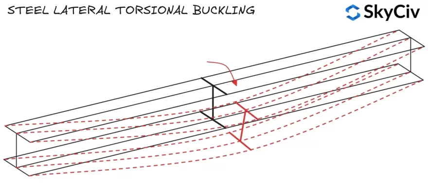
Η αντίσταση λυγισμού πλευρικής στρέψης υπολογίζεται χρησιμοποιώντας τον παρακάτω τύπο:
\(Μ_{σι,Rd} = χ_{LT}*W*f_y/ γ_{Μ1}\)
Όπου W είναι ο συντελεστής πλαστικής διατομής (Δπαρακαλώ) για την Τάξη 1 & 2 τμήματα, ή συντελεστή ελαστικής διατομής (Δο) για την Τάξη 3 τμήματα. χLT είναι ένας συντελεστής μείωσης για τον πλευρικό-στρεπτικό λυγισμό, καθοδήγηση για τον υπολογισμό αυτού του συντελεστή παρέχεται στο EN 1993-1-1 Ρήτρα 6.3.2.2 και 6.3.2.3.
Φλάντζα συμπίεσης
Τα μέλη αποτυγχάνουν στον πλευρικό λυγισμό όταν η φλάντζα συμπίεσης περιστρέφεται και μετατοπίζεται πλευρικά. Εάν η φλάντζα συμπίεσης ενός μέλους είναι επαρκώς συγκρατημένη, δεν θα είναι ευαίσθητο σε πλευρικό λυγισμό στρέψης (Ανατρέξτε στο EN 1993-1-1 Ρήτρα 6.3.2.1(2)). Οι θέσεις φλάντζας συμπίεσης για τυπικά τμήματα υπό κατακόρυφη φόρτιση φαίνονται παρακάτω.
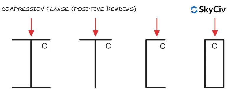
Κυκλικές κοίλες τομές (CHS) και Τετράγωνες κοίλες τομές (SHS) δεν είναι ευαίσθητα σε πλευρικό λυγισμό στρέψης, καθώς έχουν ίση αντίσταση ροπής διατομής και στους δύο άξονες (που σημαίνει ότι η πλευρική μετατόπιση και η περιστροφή δεν επηρεάζουν την αντίσταση κάμψης του μέλους).
Πλευρικός συντελεστής μείωσης του λυγισμού
χLT υπολογίζεται στο en 1993-1-1 χρησιμοποιώντας κάθε ενότητα 6.3.2.2 (Γενική υπόθεση) ή τμήμα 6.3.2.3 (Κυλινδρικά τμήματα ή ισοδύναμα συγκολλημένα τμήματα). Ενότητα 6.3.2.3 ισχύει για όλους “πρότυπο” τμήματα και σχήματα (συμπεριλαμβανομένων κοίλων τμημάτων) και τα συγκολλημένα ισοδύναμα τους. Ενότητα 6.3.2.2 ισχύει για οποιοδήποτε τμήμα που δεν εμπίπτει στην προηγούμενη κατηγορία, συμπεριλαμβανομένων των προσαρμοσμένων κατασκευασμένων και κατασκευασμένων τμημάτων.
Ενότητα 6.3.2.2 Χρησιμοποιεί εξίσωση 6.56 Για τον υπολογισμό της πλευρικής στρεπτικής μείωσης του λυγισμού Fact0r χLT ενώ τμήμα 6.3.2.3 Χρησιμοποιεί εξίσωση 6.57. ο SkyCiv ONE 1993-1-1 Σχεδιασμός μελών χάλυβα Η ενότητα ακολουθεί τη λογική που περιγράφεται παρακάτω για την εφαρμογή της εξίσωσης 6.56 και 6.57.
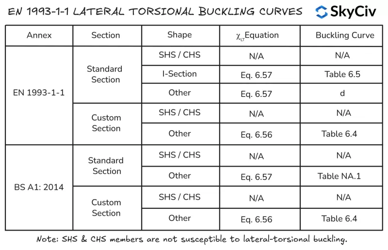
Αντίσταση κάμψης ελάσσονος άξονα
Η ικανότητα κάμψης για ένα μέλος λυγισμένο γύρω από τον δευτερεύοντα άξονά του είναι ίση με την αντίσταση του τμήματος δευτερεύοντος άξονα γύρω από αυτόν τον άξονα. Η χωρητικότητα του τμήματος δευτερεύοντος άξονα είναι η ελάχιστη χωρητικότητα που μπορεί να επιτύχει ένα τμήμα για οποιονδήποτε άξονα, Ως εκ τούτου, το μέλος δεν μπορεί να περιστραφεί από αυτόν τον άξονα σε λιγότερο ευνοϊκό προσανατολισμό.
Υπολογισμός της αντίστασης κάμψης μέλους στο EN 1993-1-1 Σχεδιασμός μελών χάλυβα
ο SkyCiv ONE 1993-1-1 Σχεδιασμός μελών χάλυβα Το εργαλείο υπολογισμού πραγματοποιεί υπολογισμούς αντίστασης πλευρικής στρέψης σύμφωνα με το EN 1993-1-1 Ρήτρα 6.3.2.2 και ρήτρα 6.3.2.3, ανάλογα με το σχήμα του τμήματος και το εφαρμοζόμενο Εθνικό Παράρτημα. Οι χρήστες έχουν επίσης την επιλογή να καθορίσουν ένα μέλος ως μέλος “Συνεχής στρεπτική συγκράτηση” που θα παρακάμψει αυτόματα όλους τους ελέγχους λυγισμού πλευρικής στρέψης. Υπολογισμοί αντίστασης λυγισμού πλευρικής στρέψης για 254 μήκους 5000 mm×102 Μπορείτε να βρείτε μια σειρά τύπων σύνδεσης που ταιριάζουν στις ανάγκες σας χωρίς να αντιμετωπίζετε ακατάστατα συστήματα διεπαφής χρήστη που απαιτούν μια απότομη καμπύλη εκμάθησης για να ξεκινήσετε 28 αναφέρονται αναλυτικά παρακάτω.

Συμπίεση
Αντίσταση κάμψης λυγισμού
Η αντίσταση λυγισμού σε συμπίεση ενός μέλους επηρεάζεται επίσης από το μήκος και την πλευρική του ακαμψία. Ασυγκράτητος, Τα μακρύτερα μέλη είναι πιθανό να αποτύχουν λόγω κάμψης πριν από το τμήμα (σκουός) έχει επιτευχθεί η χωρητικότητα. ΣΕ 1993-1-1 Ρήτρα 6.3.1.3 παρέχει οδηγίες για τον υπολογισμό της αντίστασης κάμψης λυγισμού μέλους για την Κλάση 1, 2 & 3 διατομές:
\(Ν_{σι,Rd} = χ*A*f_y/ γ_{Μ1}\)
Οπου Το χ είναι ένας συντελεστής μείωσης για τον καμπτικό λυγισμό. Οδηγίες για τον υπολογισμό αυτού του συντελεστή παρέχονται στο EN 1993-1-1 Ρήτρα 6.3.1.3. φάΗ λεξιλογική ικανότητα πρέπει να ελεγχθεί και για τους δύο άξονες για να βρεθεί η ισχύουσα τιμή για το μέλος.
Υπολογισμός της αντίστασης κάμψης λυγισμού στο EN 1993-1-1 Σχεδιασμός μελών χάλυβα
ο SkyCiv ONE 1993-1-1 Σχεδιασμός μελών χάλυβα Το εργαλείο υπολογίζει την αντίσταση κάμψης και για τους δύο κύριους άξονες με βάση τα μήκη συγκράτησης και τους παράγοντες πραγματικού μήκους που καθορίζονται από τον χρήστη. Αντίσταση κάμψης λυγισμού ενός 254×102 Μπορείτε να βρείτε μια σειρά τύπων σύνδεσης που ταιριάζουν στις ανάγκες σας χωρίς να αντιμετωπίζετε ακατάστατα συστήματα διεπαφής χρήστη που απαιτούν μια απότομη καμπύλη εκμάθησης για να ξεκινήσετε 28 με ασυγκράτητο μήκος 6000mm και 5000mm στον άξονα Z και Y (αντίστοιχα) αναφέρονται αναλυτικά παρακάτω.

Αντίσταση λυγισμού στρέψης-κάμψης
Οι ανοιχτές διατομές είναι επίσης επιρρεπείς σε λυγισμό στρέψης-κάμψης, η οποία μπορεί να είναι μικρότερη από την αντίσταση του μέλους στον καμπτικό λυγισμό. Κυκλικές κοίλες τομές (CHS) και Τετράγωνες κοίλες τομές (SHS) τα μέλη δεν είναι επιρρεπή σε λυγισμό στρέψης-κάμψης. ΣΕ 1993-1-1 Ρήτρα 6.3.1.4 παρέχει καθοδήγηση για τον υπολογισμό της αντίστασης στρέψης-κάμψης λυγισμού του μέλους:
\(Ν_{bT,Rd} = χ_T*A*f_y/ γ_{Μ1}\)
Οπου χLT είναι συντελεστής μείωσης για λυγισμό στρέψης-κάμψης. Οδηγίες για τον υπολογισμό αυτού του συντελεστή παρέχονται στο EN 1993-1-1 Ρήτρα 6.3.1.3. φάΗ λεξιλογική ικανότητα πρέπει να ελεγχθεί και για τους δύο άξονες για να βρεθεί η ισχύουσα τιμή για το μέλος.
Υπολογισμός της αντίστασης λυγισμού στρέψης-κάμψης στο EN 1993-1-1 Σχεδιασμός μελών χάλυβα
ο SkyCiv ONE 1993-1-1 Εργαλείο σχεδιασμού μελών από χάλυβα υπολογίζει την αντίσταση στρέψης-κάμψης λυγισμού για τα εφαρμοστέα ανοιχτά και κλειστά τμήματα σύμφωνα με το EN 1993-1-1 Ρήτρα 6.3.1.4 με βάση το μήκος συγκράτησης συμπίεσης στον κύριο άξονα, όπως καθορίζεται από τον χρήστη. Αντοχή λυγισμού στρέψης-κάμψης ενός 254×102 Μπορείτε να βρείτε μια σειρά τύπων σύνδεσης που ταιριάζουν στις ανάγκες σας χωρίς να αντιμετωπίζετε ακατάστατα συστήματα διεπαφής χρήστη που απαιτούν μια απότομη καμπύλη εκμάθησης για να ξεκινήσετε 28 με ασυγκράτητο μήκος 6000mm αναφέρονται αναλυτικά παρακάτω.

Λογισμικό δομικού σχεδιασμού SkyCiv
Το SkyCiv προσφέρει ένα ευρύ φάσμα Λογισμικό Κατασκευαστικής Ανάλυσης και Μηχανικού Σχεδιασμού, συμπεριλαμβανομένου:
-
- Ευρωκώδικας 3 Σχεδιασμός χάλυβα
- Ευρωκώδικας 9 Σχεδιασμός αλουμινίου
- Ευρωκώδικας 3 Σχεδιασμός τεγίδων
- Ευρωκώδικας 3 Υπολογιστής ομάδας Bolt
- Ευρωκώδικας 3 Υπολογιστής ομάδας συγκόλλησης
- Ευρωκώδικας 2 Υπολογιστής μήκους ανάπτυξης
- Ευρωκώδικας 2 Υπολογιστής μήκους γύρου
- Ευρωκώδικας 5 Υπολογιστής σχεδίασης ξυλείας
- Ευρωκώδικας 3 Υπολογιστής σχεδίασης ικριωμάτων
Προγραμματιστής λογισμικού | Δομικός μηχανικός
BEng (Εμφύλιος), DipEng (Λογισμικό)


