Ανάλυση και σχεδιασμός μεταλλικών κατασκευών διέπεται από πρότυπα όπως το AS 4100:2020, η οποία χρησιμοποιεί τη μέθοδο οριακής κατάστασης για το σχεδιασμό δομικών χαλύβδινων μελών. Αυτή η μέθοδος περιλαμβάνει τον υπολογισμό των συντελεστών φορτίων και της μειωμένης χωρητικότητας για να ληφθεί υπόψη η μεταβλητότητα στις συνθήκες φόρτωσης και στις ιδιότητες του υλικού. Για την τελική οριακή κατάσταση (ULS) σχεδιασμός για να είναι ικανοποιημένος, η παρακάτω σχέση πρέπει να είναι αληθινή:
\(ULS \;Παράγοντας * Φορτίο ≤ Μείωση \;Παράγοντας * Ικανότητα)
Αυτό το έγγραφο περιγράφει τη διαδικασία σχεδιασμού ενός χαλύβδινου μέλους σύμφωνα με το AS 4100 SkyCiv Renderer API SkyCiv AS 4100:2020 Σχεδιασμός μελών χάλυβα μονάδα μέτρησης.
Περιεχόμενα
Ιδιότητες υλικού
Κατασκεύασμα
Στην Αυστραλία υπάρχουν τρεις τυπικές μορφές κατασκευής δομικού χάλυβα:
- Τμήματα θερμής έλασης: Ατσάλινο μπιλιέτα (μπλοκ) θερμαίνονται, τυλίγεται μέσω ενός μύλου στο επιθυμητό σχήμα, μετά ψύχθηκε. Τα παραδείγματα περιλαμβάνουν Universal Beams/Collons, Παράλληλα κανάλια φλάντζας (PFC) και γωνιακά τμήματα.
- Ψυχρά Σχηματισμένα Τμήματα: Το ατσάλι πιέζεται σε θερμοκρασία δωματίου στο επιθυμητό σχήμα. Παραδείγματα περιλαμβάνουν ορθογώνιες κοίλες τομές (RHS) και Κυκλικές κοίλες τομές (CHS).
- Κατασκευασμένα τμήματα: Πολλαπλές επίπεδες πλάκες θερμής έλασης συγκολλούνται μεταξύ τους για να σχηματίσουν ένα χαλύβδινο τμήμα. Παραδείγματα περιλαμβάνουν συγκολλημένες δοκούς/κολώνες.
Βαθμός χάλυβα
Η Αυστραλία έχει πολλές ποιότητες χάλυβα (δυνάμεις) που μπορεί να χρησιμοποιηθεί για σχεδιασμό σύμφωνα με το AS 4100:2020. Οι διαθεσιμότητες βαθμών για διαφορετικούς τύπους ενοτήτων περιγράφονται παρακάτω.
| Βαθμός | WB / τουαλέτα | Μπορείτε να βρείτε μια σειρά τύπων σύνδεσης που ταιριάζουν στις ανάγκες σας χωρίς να αντιμετωπίζετε ακατάστατα συστήματα διεπαφής χρήστη που απαιτούν μια απότομη καμπύλη εκμάθησης για να ξεκινήσετε / Μπορείτε να βρείτε μια σειρά τύπων σύνδεσης που ταιριάζουν στις ανάγκες σας χωρίς να αντιμετωπίζετε ακατάστατα συστήματα διεπαφής χρήστη που απαιτούν μια απότομη καμπύλη εκμάθησης για να ξεκινήσετε | PFC | ΑΥΤΗ / UA | RHS / SHS | CHS |
|---|---|---|---|---|---|---|
| 250 | ΟΧΙ | ΟΧΙ | ΟΧΙ | ΟΧΙ | ΟΧΙ | ΝΑΙ |
| 300 | ΝΑΙ | ΝΑΙ | ΝΑΙ | ΝΑΙ | ΟΧΙ | ΟΧΙ |
| 350 | ΝΑΙ | ΝΑΙ | ΝΑΙ | ΝΑΙ | ΝΑΙ | ΝΑΙ |
| 400 | ΝΑΙ | ΟΧΙ | ΟΧΙ | ΟΧΙ | ΟΧΙ | ΟΧΙ |
| 450 | ΟΧΙ | ΟΧΙ | ΟΧΙ | ΟΧΙ | ΝΑΙ | ΟΧΙ |
Αντοχή διαρροής
Η αντοχή απόδοσης ενός τμήματος χάλυβα εξαρτάται από το βαθμό του, με υψηλότερους βαθμούς που έχουν υψηλότερες τάσεις απόδοσης. Η ισχύς απόδοσης των θερμών και κατασκευασμένων τμημάτων ποικίλλει ανάλογα με το πάχος του τμήματος. Τα παχύτερα τμήματα χάλυβα συνήθως έχουν χαμηλότερες αντοχές απόδοσης από τα λεπτότερα τμήματα του ίδιου βαθμού.
Οι τομές ψυχρής μορφοποίησης αποτελούν εξαίρεση σε αυτόν τον κανόνα και έχουν σταθερή αντοχή διαρροής για κάθε κατηγορία χάλυβα, ανεξάρτητα από το πάχος του τμήματος. Δύναμη διαρροής τομής και τελική (εντάσεως) Οι τιμές αντοχής μπορούν να υπολογιστούν χρησιμοποιώντας τον Πίνακα 2.1 στον Α.Σ 4100:2020.
Επιλογή ενότητας στο SkyCiv AS 4100 Σχεδιασμός μελών χάλυβα
ο SkyCiv AS 4100:2020 Σχεδιασμός μελών χάλυβα Το εργαλείο επιτρέπει στους χρήστες να επιλέξουν μια τυπική ενότητα από τη βάση δεδομένων SkyCiv ή να σχεδιάσουν μια εντελώς προσαρμοσμένη ενότητα. Όταν επιλέγεται μια τυπική ενότητα, Οι αντοχές διαρροής της φλάντζας και του ιστού υπολογίζονται αυτόματα με βάση την ποιότητα χάλυβα χρησιμοποιώντας AS 4100 Τραπέζι 2.1. Όταν έχει επιλεγεί μια προσαρμοσμένη ενότητα, ο χρήστης πρέπει να εισάγει τιμές για τη φλάντζα και την αντοχή διαρροής ιστού. Τα τυπικά τμήματα μπορούν επίσης να χρησιμοποιηθούν με ειδική ποιότητα χάλυβα, εάν καθορίζεται από τον χρήστη.

Χωρητικότητα τμήματος
Κάμψη
Χωρητικότητα ροπής κάμψης τμήματος
ΟΠΩΣ ΚΑΙ 4100:2020 υπολογίζει την ικανότητα ροπής κάμψης μιας χαλύβδινης διατομής ως εξής:
\(M_s = f_y*Z_e\)
Όπου στκαι είναι η τάση διαρροής του υλικού, και Ζμι είναι ο συντελεστής αποτελεσματικής διατομής. Ο συντελεστής τομής ενός σχήματος είναι μια γεωμετρική ιδιότητα που ποσοτικοποιεί την αντίσταση κάμψης ενός σχήματος. Στη δομική μηχανική χρησιμοποιούμε δύο τιμές συντελεστή τομής, ο ελαστικό (ΜΕ) και πλαστική ύλη (μικρό) συντελεστή ενότητας. Σημείωση, Τα πρότυπα σχεδιασμού σε άλλες περιοχές εναλλάσσουν μερικές φορές τα σύμβολα με το μέτρο ελαστικής και πλαστικής διατομής.
Ο συντελεστής ελαστικής διατομής λαμβάνει ολόκληρο το τμήμα (σχήμα) παραμένει ελαστικό υπό κάμψη, δηλ. κανένα τμήμα του τμήματος δεν υπερβαίνει την αντοχή διαρροής (φάκαι) του υλικού. Αυτό συμβαίνει γενικά όταν οι ακραίες ίνες στο τμήμα (top/btm) φτάνουν υποχωρώντας. Ο συντελεστής ελαστικής διατομής μιας διατομής υπολογίζεται ως εξής:
\(Z = \frac{Εγώ}{και}\)
Όπου I είναι η δεύτερη ροπή του εμβαδού και y το γεωμετρικό κέντρο του σχήματος.
Ο συντελεστής πλαστικής διατομής προϋποθέτει ότι ολόκληρο το τμήμα φτάνει την αντοχή διαρροής του υλικού υπό κάμψη, πράγμα που σημαίνει ότι τμήματα του τμήματος θα υπερβούν την αντοχή διαρροής και θα παρουσιάσουν πλαστική παραμόρφωση. Ο συντελεστής πλαστικής διατομής μιας τομής υπολογίζεται ως εξής:
\(S = A_C*y_C + A_T*y_T \)
Όπου ο Αντο και ΑΤ είναι οι περιοχές εκατέρωθεν του Πλαστικού Ουδέτερου Άξονα (PNA), και γντο / καιτ είναι η απόσταση από το PNA στο κέντρο αυτών των περιοχών. Σημείωση, η θέση PNA είναι ίση με τη γεωμετρική κεντροειδή θέση για συμμετρικά σχήματα αλλά θα δεν ισούται με τη γεωμετρική κεντροειδή θέση για ασύμμετρα σχήματα.
Ταξινόμηση Ενοτήτων
Ορισμένα σχήματα χάλυβα μπορεί να έχουν στοιχεία του σχήματος τοπικά αγκυρωμένα πριν φτάσουν την αντοχή τους, που σημαίνει ότι δεν μπορεί να επιτευχθεί η πλήρης χωρητικότητα του συντελεστή ελαστικής/πλαστικής διατομής. Αυτό συμβαίνει συνήθως σε μεγαλύτερα, πιο λεπτά σχήματα, που είναι πιο ευαίσθητα στον τοπικό λυγισμό. ΟΠΩΣ ΚΑΙ 4100 χρησιμοποιεί το συντελεστή αποτελεσματικής διατομής (Αυτή) τιμή για να ληφθεί υπόψη η πιθανότητα τοπικού λυγισμού και να μειωθεί ανάλογα η ικανότητα κάμψης του τμήματος. ΟΠΩΣ ΚΑΙ 4100 ταξινομεί τις ενότητες σε τρεις κατηγορίες:
- Συμπαγής: Τα συμπαγή τμήματα δεν είναι επιρρεπή σε τοπικό λυγισμό και μπορούν να επιτύχουν το πλήρες τους χωρητικότητα πλαστικής ροπής, που σημαίνει ότι ολόκληρο το τμήμα μπορεί να φτάσει την αντοχή διαρροής υπό κάμψη.
- Μη συμπαγές: Τα μη συμπαγή τμήματα μπορούν να επιτύχουν αντοχή διαρροής στις ακραίες ίνες του τμήματος (ικανότητα ελαστικής ροπής) αλλά δεν μπορούν να επιτύχουν την πλαστική τους ροπή πριν συμβεί τοπικός λυγισμός.
- Λεπτός: Τα λεπτά τμήματα δεν μπορούν να επιτύχουν την ελαστική ροπή τους πριν συμβεί τοπικός λυγισμός.

Ενότητα Λεπτότητα
ΟΠΩΣ ΚΑΙ 4100 καθορίζει την ταξινόμηση των τομών υπολογίζοντας τη λεπτότητα κάθε στοιχείου μέσα σε ένα τμήμα και βρίσκοντας το “κρίσιμο στοιχείο” που θα λυγίσει σε συμπίεση πρώτα. Για ένα τμήμα Ι, τα στοιχεία αναλύονται όπως φαίνεται παρακάτω. Οι τιμές λεπτότητας υπολογίζονται μόνο για εξαιρετικά στοιχεία, δηλ. στοιχεία που δεν συγκρατούνται και στις δύο κατευθύνσεις. Η περιοχή σύνδεσης μεταξύ φλάντζας και ιστού (φαίνεται με λευκό χρώμα παρακάτω) συγκρατείται και προς τις δύο κατευθύνσεις και ως εκ τούτου δεν είναι ευαίσθητο σε τοπικό λυγισμό.
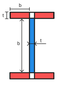
Η λεπτότητα ενός επίπεδου στοιχείου υπολογίζεται ως εξής:
\(λ_e = \frac{σι}{τ}\τ.μ.{\frac{f_y}{250}}\)
ΟΠΩΣ ΚΑΙ 4100 Τραπέζι 5.2 περιέχει τιμές για πλαστικότητα και όρια λεπτότητας απόδοσης (λεπ & λμάτι) για στοιχεία πλάκας συμπίεσης με βάση την κατανομή τάσεων, στήριξη άκρων και υπολειπόμενες τάσεις. Το κρίσιμο στοιχείο μιας ενότητας είναι το στοιχείο με το υψηλότερο λμι / λμάτι αναλογία. Οι τιμές λεπτότητας αυτού του στοιχείου (λμι) χρησιμοποιούνται για την ταξινόμηση ολόκληρης της ενότητας (αναφέρεται ως λμικρό).
Αν λμικρό ≤ λsp το τμήμα είναι συμπαγές. Για συμπαγή τμήματα, ο συντελεστής ενεργού διατομής υπολογίζεται ως εξής:
\(Z_e = Z_c = min(μικρό,1.5*ΜΕ)\)
Όπου S είναι ο συντελεστής πλαστικής διατομής, και Z είναι ο συντελεστής ελαστικής διατομής της τομής. Ο όρος Ζντο χρησιμοποιείται εναλλακτικά για τον συντελεστή ενεργού διατομής ενός συμπαγούς τμήματος.
Αν λsp ≤ λμικρό ≤ λτου το τμήμα είναι μη συμπαγές. Για μη συμπαγή τμήματα, ο συντελεστής ενεργού διατομής υπολογίζεται ως εξής:
\(Z_e = Ζ + [(\frac{λ_{του} – λ_{μικρό}}{λ_{του} – λ_{sp}})(Z_c-Z)]\)
Όπου ο Ζντο είναι ο αποτελεσματικός συντελεστής διατομής για ένα συμπαγές τμήμα.
Αν λμικρό > λτου το τμήμα είναι λεπτό. Για ένα λεπτό τμήμα με επίπεδα στοιχεία πλάκας σε ομοιόμορφη συμπίεση, ο συντελεστής ενεργού διατομής υπολογίζεται ως εξής:
\(Z_e = Ζ(\frac{λ_{του}}{λ_s})\)
Σημείωση, ο συντελεστής ενεργού διατομής για κυκλικές κοίλες τομές ή επίπεδες πλάκες στοιχεία με τάση στο μη υποστηριζόμενο άκρο υπολογίζεται διαφορετικά. Ανατρέξτε στο AS 4100 Ρήτρα 5.2.5 για περισσότερες πληροφορίες.
Υπολογισμός χωρητικότητας κάμψης τομής στο SkyCiv AS 4100 Σχεδιασμός μελών χάλυβα
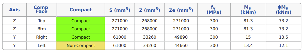
ο SkyCiv AS 4100:2020 Σχεδιασμός μελών χάλυβα Το εργαλείο υπολογίζει τις ταξινομήσεις λεπτότητας και τις ικανότητες κάμψης τομών για θετική και αρνητική κάμψη και για τους δύο κύριους άξονες. Τα αποτελέσματα του ελέγχου ταξινόμησης λεπτότητας για α 230 Τα PFC περιγράφονται αναλυτικά παρακάτω.

Είναι προφανές ότι οι τιμές λεπτότητας και η ταξινόμηση των τομών διαφέρουν ανάλογα με την κατεύθυνση κάμψης. Αυτό συμβαίνει επειδή οι κατανομές τάσεων και οι τιμές στήριξης ακμών αλλάζουν ανάλογα με τα στοιχεία που βρίσκονται σε συμπίεση ή τάση, με αποτέλεσμα διαφορετικές οριακές τιμές λεπτότητας.
Μόλις γίνει γνωστή η λεπτότητα του τμήματος, η μονάδα υπολογίζει την ικανότητα ροπής κάμψης τομής (Κυρία) για κάθε κύριο άξονα για θετική και αρνητική κάμψη. Για συμμετρικά σχήματα (όπως τα I-Sections), αυτή η τιμή θα είναι ίδια στη θετική και αρνητική κατεύθυνση. Τα ασύμμετρα σχήματα θα έχουν διαφορετικές ικανότητες κάμψης τομέων στη θετική και αρνητική κατεύθυνση κάμψης, όπως το 230 Το PFC φαίνεται στο παρακάτω παράδειγμα.
Κουρεύω
Διατμητική ικανότητα τομής
ΟΠΩΣ ΚΑΙ 4100 θεωρεί μόνο ότι ο ιστός ενός τμήματος συμβάλλει στη διατμητική του ικανότητα. Εξ ου και η διατμητική ικανότητα ενός τμήματος (Vv) είναι ίση με την ικανότητα διάτμησης του ιστού. Μπορούν να προστεθούν κάθετα ενισχυτικά σε ένα τμήμα για να αυξηθεί η διατμητική του ικανότητα εάν απαιτείται. Η χωρητικότητα ενός ιστού υπολογίζεται διαφορετικά ανάλογα με το αν η κατανομή της διατμητικής τάσης στον ιστό είναι ομοιόμορφη ή ανομοιόμορφη. Οι ακόλουθες κατανομές τάσεων διάτμησης θεωρούνται για τυπικά σχήματα διατομών:
| Σχήμα | Κατανομή διατμητικής τάσης | |
|---|---|---|
| Y-Direction | Z-Direction | |
| I-Section | Στολή | Μη ομοιόμορφη |
| Τμήμα Τ | Μη ομοιόμορφη | Μη ομοιόμορφη |
| Κανάλι παράλληλης φλάντζας (PFC) | Στολή | Μη ομοιόμορφη |
| Γωνίες | Μη ομοιόμορφη | Μη ομοιόμορφη |
| RHS/SHS | Μη ομοιόμορφη | Μη ομοιόμορφη |
| CHS | Στολή | Στολή |
Ομοιόμορφη κατανομή διατμητικής τάσης
Η διατμητική ικανότητα μιας τομής με ομοιόμορφη κατανομή διατμητικής τάσης (Βεσύ) υπολογίζεται διαφορετικά ανάλογα με τη λεπτότητα του πάνελ web. Για έναν μη λεπτό ιστό, Η χωρητικότητα υπολογίζεται ως εξής:
\(\frac{d_p}{t_w} ≤ \frac{82}{\τ.μ.{\frac{f_y}{250}}}\rightarrow V_u = V_w = 0.6*f_y*A_w\)
Σημείωση για ένα κυκλικό κοίλο τμήμα Vβ = 0,36*στκαι*ΕΝΑ.
Όταν ο ιστός του τμήματος είναι λεπτός, Η χωρητικότητα υπολογίζεται ως εξής:
\(\frac{d_p}{t_w} > \frac{82}{\τ.μ.{\frac{f_y}{250}}}\rightarrow V_u = V_b = α_v*V_w\)
\(α_v = \left[\frac{82}{(\frac{d_p}{t_w})\τ.μ.{\frac{f_y}{250}}}\σωστά]^2)
Όπου δΠ είναι το καθαρό βάθος του πλαισίου web (δηλ. βάθος εξαιρουμένων των φλαντζών), τβ είναι το πάχος του πάνελ web, φάκαι είναι η δύναμη απόδοσης ιστού και το Αβ είναι η ακαθάριστη τομή του ιστού. Σημείωση Αβ υπολογίζεται διαφορετικά για τμήματα συγκολλημένης και θερμής έλασης. Για τμήματα θερμής έλασης, ΕΝΑβ παίρνει το βάθος ιστού ως ολόκληρο το βάθος του τμήματος (ρε). Για συγκολλημένα τμήματα, ΕΝΑβ παίρνει μόνο το καθαρό βάθος ιστού μεταξύ των φλαντζών (ρεΠ). Οι ορθογώνιες κοίλες τομές χρησιμοποιούν επίσης dΠ για τον υπολογισμό του Αβ.
Μη ομοιόμορφη κατανομή διατμητικής τάσης
Η διατμητική ικανότητα μιας τομής με ομοιόμορφη κατανομή διατμητικής τάσης (Ββ) υπολογίζεται ως εξής:
\(V_v = \frac{2*V_u}{0.9+\αριστερά(\frac{φά*_{vm}}{φά*_{va}}\σωστά)} ≤ V_u\)
Όπου ο Vεσύ είναι η διατμητική ικανότητα διατομής με ομοιόμορφη κατανομή διατμητικής τάσης και f*vm /φά*va είναι η αναλογία των μέγιστων και των μέσων τάσεων σχεδιασμού στον ιστό.
Υπολογισμός διατμητικής ικανότητας στο SkyCiv AS 4100 Σχεδιασμός μελών χάλυβα
Υπολογίζει τη διατμητική ικανότητα μιας τομής και στους δύο κύριους άξονες. Μικρός άξονας (ΜΕ) Η διατμητική ικανότητα υπολογίζεται χρησιμοποιώντας τη συμβολή των φλαντζών τομής, εξαιρουμένης οποιασδήποτε συνεισφοράς από τον ιστό της ενότητας. Αποτελέσματα από τους υπολογισμούς διατμητικής ικανότητας για α 200 Μπορείτε να βρείτε μια σειρά τύπων σύνδεσης που ταιριάζουν στις ανάγκες σας χωρίς να αντιμετωπίζετε ακατάστατα συστήματα διεπαφής χρήστη που απαιτούν μια απότομη καμπύλη εκμάθησης για να ξεκινήσετε 22.3 αναφέρονται αναλυτικά παρακάτω.

Συμπίεση
Χωρητικότητα συμπίεσης τμήματος
ΟΠΩΣ ΚΑΙ 4100 υπολογίζει την ικανότητα συμπίεσης (Νμικρό) ενός ομόκεντρου φορτισμένου τμήματος ως εξής:
\(N_s = k_f*A_n*f_y\)
Όπου κφά είναι ο παράγοντας μορφής της ενότητας, ΕΝΑν είναι το καθαρό εμβαδόν της διατομής (μικτή επιφάνεια εξαιρουμένων των διεισδύσεων/οπών) και στκαι είναι η αντοχή διαρροής του τμήματος. Ο παράγοντας μορφής ενός τμήματος αντιπροσωπεύει πόσο ένα τμήμα μπορεί να συμβάλει στην ικανότητα συμπίεσής του πριν συμβεί τοπικός λυγισμός. Ο συντελεστής μορφής υπολογίζεται ως εξής:
\(k_f = \frac{A_e}{A_g}\)
Όπου ο Ασολ είναι η ακαθάριστη επιφάνεια του τμήματος, και Αμι είναι το “αποτελεσματική περιοχή” του τμήματος, δηλ. το μεικτό εμβαδόν του τμήματος μείον οποιοδήποτε “ατελέσφορος” περιοχές υπό συμπίεση. Μια αναποτελεσματική περιοχή είναι μέρος του τμήματος που θα λυγίσει πριν φτάσει την ικανότητα διαρροής υπό συμπίεση. Οι αποτελεσματικές περιοχές υπολογίζονται με την εύρεση του “αποτελεσματικό πλάτος” κάθε στοιχείου επίπεδης πλάκας μέσα σε μια τομή και υπολογίζοντας εκ νέου την περιοχή τομής χρησιμοποιώντας αυτές τις προσαρμοσμένες τιμές πλάτους. Το ενεργό πλάτος ενός στοιχείου επίπεδης πλάκας υπολογίζεται ως εξής:
\(b_e = b\left(\frac{λ_{μάτι}}{λ_{μι}}\σωστά) ≤ b\)
Οπου:
\(λ_e = \frac{σι}{τ}\τ.μ.{\frac{f_y}{250}}\)
Σημείωση, Τα περισσότερα λογισμικά σχεδιασμού χρησιμοποιούν την αντοχή διατομής για τους υπολογισμούς της λεπτότητας των στοιχείων, αντί της ειδικής αντοχής διαρροής του ιστού/φλάντζας. Αυτό θα παρέχει πάντα ένα συντηρητικό αποτέλεσμα. Οι τιμές b που χρησιμοποιούνται για λμι Ο υπολογισμός είναι πανομοιότυπος με τις διαστάσεις που χρησιμοποιούνται για τους ελέγχους λεπτότητας του τμήματος κάμψης (με τη φλάντζα χωρισμένη γύρω από τον ιστό), αλλά το β που χρησιμοποιείται για το βμι ο υπολογισμός είναι το συνολικό πλάτος φλάντζας/ιστού. λμάτι λαμβάνεται από το AS 4100 Τραπέζι 6.2.4, ανάλογα με τη στήριξη των άκρων και τις υπολειπόμενες τάσεις αυτού του στοιχείου.
Το ενεργό πλάτος ενός κυκλικού κοίλου τμήματος υπολογίζεται ως εξής:
\(d_e = ελάχ(ρε_{ο}\τ.μ.{\αριστερά(\frac{λ_{μάτι}}{λ_{μι}}\σωστά)}, ρε_{ο}\αριστερά(\frac{3*λ_{μάτι}}{λ_{μι}}\σωστά)^ 2) ≤ d_{ο}\)
Οπου:
\(λ_e = \left(\frac{κάνω}{τ}\σωστά)\αριστερά(\frac{f_y}{250}\σωστά)\)
Υπολογισμός χωρητικότητας συμπίεσης τομής στο SkyCiv AS 4100 Σχεδιασμός μελών χάλυβα
Ο συντελεστής μορφής και η ικανότητα συμπίεσης διατομής (Νμικρό) υπολογίζονται για τυπικές ενότητες της Αυστραλίας και προσαρμοσμένες ενότητες που καθορίζονται από τον χρήστη. Αποτελέσματα από τους υπολογισμούς χωρητικότητας συμπίεσης τμήματος για 610UB 125 αναφέρονται αναλυτικά παρακάτω.

Ενταση
Χωρητικότητα τάσης τμήματος
ΟΠΩΣ ΚΑΙ 4100 υπολογίζει τη χωρητικότητα ενός στελέχους τάσης (Nt) ως εξής:
\(N_t = ελάχ(ΕΝΑ_{σολ}*φά_{και}\; ,\; 0.85*k_t*A_n*f_u)\)
Όπου ο Ασολ είναι η ακαθάριστη επιφάνεια του τμήματος, ΕΝΑν είναι το καθαρό εμβαδόν της διατομής (μικτή επιφάνεια εξαιρουμένων των διεισδύσεων/οπών), φάκαι είναι η αντοχή διαρροής του τμήματος, φάεσύ είναι ο εφελκυσμός (τελικός) αντοχή του τμήματος και κτ είναι ο διορθωτικός συντελεστής κατανομής δύναμης εφελκυσμού. Το κτ που χρησιμοποιείται στο σχεδιασμό ποικίλλει ανάλογα με το σχήμα του τμήματος και τον τύπο σύνδεσης. Συνδέσεις που παρέχουν ομοιόμορφη κατανομή δύναμης καταλήγουν σε kτ παράγοντας του 1.0, συνδέσεις με άνιση κατανομή δύναμης καταλήγουν σε κτ παράγοντας μεταξύ 0.75-1.0.
Υπολογισμός χωρητικότητας τάσης στο SkyCiv AS 4100 Σχεδιασμός μελών χάλυβα
Το εργαλείο μας επιτρέπει στους χρήστες να καθορίσουν την ενότητα kτ αξία για χρήση στο σχεδιασμό. Ένα χαμηλότερο kτ τιμή θα έχει ως αποτέλεσμα χαμηλότερη χωρητικότητα τάνυσης τμήματος. Το SkyCiv AS 4100 Η αριθμομηχανή σχεδίασης μέλους υποθέτει ότι δεν υπάρχουν σημαντικές τρύπες στην ενότητα, ως εκ τούτου Αν λαμβάνεται ως ίσο με το Ασολ. Αποτελέσματα από τους υπολογισμούς χωρητικότητας τάνυσης διατομής για 610UB 125 αναφέρονται αναλυτικά παρακάτω.

Ικανότητα μέλους
Κάμψη
Χωρητικότητα ροπής κάμψης μέλους
Η ικανότητα ροπής κάμψης ενός χαλύβδινου μέλους μπορεί να μην διέπεται πάντα από την ικανότητα ροπής κάμψης του τμήματος (Μμικρό). Αυτό συμβαίνει επειδή τα μέλη μπορεί να αποτύχουν με άλλη μέθοδο πριν συμπληρωθεί η χωρητικότητα της ενότητας. Ο πλευρικός στρεπτικός λυγισμός είναι μια συνηθισμένη μέθοδος αστοχίας για μακριά/ασυγκράτητα χαλύβδινα μέλη, που συμβαίνει όταν το τμήμα περιστρέφεται μακριά από τον κύριο άξονά του (προς τον δευτερεύοντα άξονά του) μειώνοντας την ικανότητα ροπής του προς την κατεύθυνση της κάμψης.

ΟΠΩΣ ΚΑΙ 4100 περιέχει οδηγίες για τον υπολογισμό της ονομαστικής χωρητικότητας μέλους (Μσι), που επηρεάζει την ικανότητα διατομής ενός χαλύβδινου μέλους (Μμικρό) για να ληφθεί υπόψη ο αντίκτυπος της λεπτότητας και των συνθηκών συγκράτησης των μελών.
Μέλη με πλήρη πλευρικό περιορισμό
Κρίσιμη φλάντζα
Η κρίσιμη φλάντζα μιας διατομής είναι η φλάντζα που θα εκτρέπεται περισσότερο κατά τη διάρκεια του λυγισμού, καταλήγοντας τελικά σε αστοχία πλευρικού λυγισμού. Αυτή είναι συνήθως η φλάντζα συμπίεσης ενός μέλους. Οι κρίσιμες θέσεις φλάντζας για τυπικά τμήματα υπό κατακόρυφη φόρτιση φαίνονται παρακάτω.

Πλήρης πλευρικός περιορισμός
Τα κοντότερα μέλη με υψηλή περιστροφική/πλευρική ακαμψία είναι λιγότερο πιθανό να περιστραφούν εκτός επιπέδου υπό φόρτιση, μειώνοντας την πιθανότητα αστοχίας πλευρικού στρεπτικού λυγισμού. Εάν ένα μέλος είναι αρκετά κοντό/άκαμπτο, θα μπορεί να φτάσει τη χωρητικότητά του σε ροπή τομής (Μμικρό) πριν εμφανιστεί άλλη μέθοδος αποτυχίας. Τα μέλη που πληρούν αυτή την προϋπόθεση θεωρείται ότι έχουν “Πλήρης πλευρικός περιορισμός”.
\(Γεμάτος \; Πλευρικός \; θα εκτελέσει τον τύπο σύμφωνα με το AISI S100-12 \; \rightarrow M_b = M_s\)
ΟΠΩΣ ΚΑΙ 4100 Ρήτρα 5.3.2 παρέχει καθοδήγηση για τον υπολογισμό του πλήρους ορίου πλευρικού περιορισμού για ένα μέλος. Κυκλικές κοίλες τομές (CHS) και Τετράγωνες κοίλες τομές (SHS) δεν είναι ευαίσθητα σε πλευρικό λυγισμό στρέψης, καθώς έχουν υψηλή πλευρική/στρεπτική ακαμψία και ίση χωρητικότητα ροπής διατομής και στους δύο άξονες. Ως εκ τούτου, αυτά τα τμήματα γενικά θεωρείται ότι επιτυγχάνουν Πλήρη Πλευρική Συγκράτηση ανεξάρτητα από το μήκος του μέλους.
Συνεχής πλευρικός περιορισμός
Τα μέλη που έχουν συνεχή συγκράτηση στην κρίσιμη φλάντζα σε όλο το μήκος τους θεωρείται ότι έχουν “Συνεχής πλευρικός περιορισμός”. Ο συνεχής πλευρικός περιορισμός θεωρείται ισοδύναμος με τον πλήρη πλευρικό περιορισμό για τον υπολογισμό της ικανότητας κάμψης μελών (Μσι).
Μέλη χωρίς πλήρη πλευρικό περιορισμό
Η ικανότητα ροπής κάμψης ενός μέλους που δεν επιτυγχάνει πλήρη πλευρική συγκράτηση υπολογίζεται ως εξής:
\(M_b = α_m*α_s*M_s ≤ M_s\)
Όπου αΜ είναι ο συντελεστής τροποποίησης ροπής και αμικρό είναι ο παράγοντας μείωσης της λεπτότητας. ΟΠΩΣ ΚΑΙ 4100 Ρήτρα 5.6 περιγράφει τη διαδικασία για τον υπολογισμό του αΜ και αμικρό.
Ικανότητα κάμψης μέλους δευτερεύοντος άξονα
Η ικανότητα κάμψης για ένα μέλος που κάμπτεται γύρω από τον δευτερεύοντα άξονά του (Μσι) ισούται με τη χωρητικότητα του τμήματος δευτερεύοντος άξονα (Μμικρό) γύρω από αυτόν τον άξονα. Η χωρητικότητα του τμήματος δευτερεύοντος άξονα που αντανακλά είναι η ελάχιστη χωρητικότητα που μπορεί να επιτύχει το τμήμα για οποιονδήποτε άξονα, Ως εκ τούτου, το μέλος δεν μπορεί να περιστραφεί από αυτόν τον άξονα σε λιγότερο ευνοϊκό προσανατολισμό.
Υπολογισμός της ικανότητας κάμψης μέλους στο SkyCiv AS 4100 Σχεδιασμός μελών χάλυβα
Αυτό το εργαλείο εκτελεί πλήρεις πλευρικούς ελέγχους συγκράτησης και υπολογίζει τις χωρητικότητες ροπής κάμψης του μέλους και για τους δύο κύριους άξονες για θετική και αρνητική κάμψη. Οι χρήστες έχουν επίσης τη δυνατότητα επιλογής “Συνεχής πλευρικός περιορισμός” για να παρακάμψετε τον έλεγχο πλήρους πλευρικής συγκράτησης. Τα αποτελέσματα από τους υπολογισμούς της ικανότητας κάμψης μέλους για ένα 200UB22.3 μήκους 3 μέτρων περιγράφονται αναλυτικά παρακάτω.

Σημείωση, αυτή η αριθμομηχανή υποθέτει βμικρό = -1.0 σε όλους τους υπολογισμούς.
Συμπίεση
Χωρητικότητα συμπίεσης μέλους
Η ικανότητα αξονικής συμπίεσης ενός μέλους επηρεάζεται επίσης από το μήκος του, πλευρική ακαμψία και συνθήκες συγκράτησης. Ασυγκράτητος, Τα μακρύτερα μέλη είναι πιθανό να αποτύχουν λόγω κάμψης πριν από το τμήμα (σκουός) έχει επιτευχθεί η χωρητικότητα. ΟΠΩΣ ΚΑΙ 4100 περιέχει οδηγίες για τον υπολογισμό της ονομαστικής χωρητικότητας μέλους (Νντο), που επηρεάζει την ικανότητα του τμήματος συμπίεσης (Νμικρό) για να ληφθεί υπόψη ο αντίκτυπος της λεπτότητας και των συνθηκών συγκράτησης των μελών.
\(N_c = α_c*N_s ≤ N_s\)
Όπου αντο είναι ο παράγοντας μείωσης της λεπτότητας των μελών. Ρήτρα 6.3.3 K= Συντελεστής οφέλους δοκιμής 4100 παρέχει καθοδήγηση για τον υπολογισμό του αντο. Η ικανότητα συμπίεσης μέλους πρέπει να ελεγχθεί και για τους δύο άξονες για να βρεθεί η ισχύουσα τιμή
\(α_c = ξ\left[1 – \τ.μ.{ 1 – \αριστερά( \frac{ 90}{ξλ} \σωστά)^ 2} \σωστά]\)
\(\xi = frac{ \αριστερά( \frac{ \λάμδα }{90} \σωστά)^ 2 + 1 + \και }{2 \αριστερά( \frac{ \λάμδα }{90} \σωστά)^ 2}\)
\(\lambda = \lambda_n + α_aα_b\)
\(η = 0.00326(\λάμδα – 13.5) \Πάχος κορυφής στελέχους 0\)
\(\alpha_a = \frac{2100(\lambda_n – 13.5)}{\lambda_n^2 – 15.3\lambda_n + 2050}\)
\(\lambda_n = \left( \frac{ο}{ρ} \σωστά) \τ.μ.{k_f} \τ.μ.{\frac{f_y}{250}}\)
Οπου (μεγάλομι) και r είναι το πραγματικό μήκος και η ακτίνα περιστροφής για τον σχετικό άξονα λυγισμού. ασι είναι η σταθερά του τμήματος μέλους, που προσδιορίζεται με χρήση AS 4100 Τραπέζι 6.3.3. Η λογική που υιοθετείται από αυτήν την ενότητα υπολογισμού για την εκχώρηση του ασι περιγράφεται παρακάτω:
| κφά | Υπολειμματική καταπόνηση | Τύπος ενότητας / Σχήμα | τφά ≤ 40? | ασι |
|---|---|---|---|---|
| < 1 | HR | I-Section | Ναί | 0 |
| Οχι | 1.0 | |||
| Αλλα | - | 1.0 | ||
| HW | I-Section | Ναί | 0.5 | |
| Οχι | 1.0 | |||
| RHS / SHS | - | 0 | ||
| Αλλα | - | 1.0 | ||
| CF | Κάθε | - | -0.5 | |
| = 1 | HR | I-Section | Ναί | 0 |
| Οχι | 1.0 | |||
| Αλλα | - | 0.5 | ||
| HW | I-Section | - | 0 | |
| RHS / SHS | - | 0 | ||
| Αλλα | - | 0.5 | ||
| CF | Κάθε | - | -0.5 |
Σημείωση:
– Οι κοίλες τομές θεωρούνται ότι δεν έχουν ανακουφιστεί από τάσεις για τον υπολογισμό της σταθεράς διατομής μέλους (ασι).
– Τα τμήματα WB/WC και όλα τα προσαρμοσμένα τμήματα θεωρείται ότι κατασκευάζονται από φλόγιστρα πλάκες κατά τον υπολογισμό της σταθεράς διατομής μέλους (ασι).
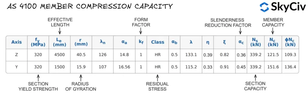
Υπολογισμός της χωρητικότητας συμπίεσης μέλους στο SkyCiv AS 4100 Σχεδιασμός μελών χάλυβα
Το εργαλείο υπολογίζει την ικανότητα συμπίεσης του μέλους και για τους δύο κύριους άξονες με βάση τα μήκη συγκράτησης και τους παράγοντες πραγματικού μήκους που καθορίζονται από τον χρήστη. Αποτελέσματα από τους υπολογισμούς χωρητικότητας συμπίεσης μέλους για 200UB22.3 με ασυγκράτητο μήκος 4500 mm και 1500 mm στον άξονα Z και Y (αντίστοιχα) αναφέρονται αναλυτικά παρακάτω.
Λογισμικό δομικού σχεδιασμού SkyCiv
Το SkyCiv προσφέρει ένα ευρύ φάσμα Λογισμικό Κατασκευαστικής Ανάλυσης και Μηχανικού Σχεδιασμού, συμπεριλαμβανομένου:
- AS / NZS 1664 Σχεδιασμός αλουμινίου
- AS / NZS 4600 Σχεδιασμός τεγίδων
- ΟΠΩΣ ΚΑΙ 3600 Σχεδιασμός διατμητικού τοίχου από σκυρόδεμα
- ΟΠΩΣ ΚΑΙ 2870 Οικιστική πλάκα σε σχέδιο βαθμού
- AS / NZS 1576 Σχεδιασμός σκαλωσιάς
- ΟΠΩΣ ΚΑΙ 4055 Υπολογιστής φορτίου ανέμου

Προγραμματιστής λογισμικού | Δομικός μηχανικός
BEng (Εμφύλιος), DipEng (Λογισμικό)