Τι σημαίνουν οι σταθερότητες των μελών και τον τρόπο με τον οποίο εντοπίζονται σε δομικά 3D
Οι σταθερότητες των τελικών μελών ελέγχουν τον τρόπο με τον οποίο τα μέλη συνδέονται μεταξύ τους ή με τους τελικούς κόμβους και περιλαμβάνουν συνθήκες όπως ένα σταθερό, καρφιτσωμένο, ή σύνδεση ελατηρίου.
Οι κωδικοί σταθερότητας μέλους αποδέχονται "F’ (Σταθερός), ‘R’ (Κυκλοφόρησε) και «Σ’ (Ανοιξη) αξίες. Αυτός ο κωδικός αναφέρεται στη σύνδεση του μέλους με τον τελικό κόμβο του για καθένα από τα 6 βαθμοί ελευθερίας με την ακόλουθη σειρά:
- Τοπική μετάφραση άξονα x
- Τοπική μετάφραση άξονα y
- Τοπική μετάφραση άξονα z
- Τοπική περιστροφή άξονα x
- Τοπική περιστροφή του άξονα y
- Τοπική περιστροφή άξονα z
ΣΗΜΕΙΩΣΗ: Οι σταθερότητες μέλους είναι σε σχέση με τα μέλη τοπικό σύστημα άξονα αντί του παγκόσμιου συστήματος άξονα.
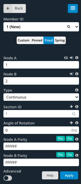
Σταθερός Τα μέλη έχουν πλήρως σταθερά, άκαμπτη σύνδεση που καθορίζεται από έναν κωδικό σταθερότητας του 'ffffff'.
Καρφιτσώθηκε Τα μέλη έχουν μια αρθρωτή σύνδεση που υποδηλώνει ένας κώδικας του 'ffffrr'.
Ανοιξη τα μέλη έχουν μια ημιάκαμπτη σύνδεση που επιτρέπει μερική ευελιξία που υποδηλώνεται με έναν κωδικό «FFFFSS».
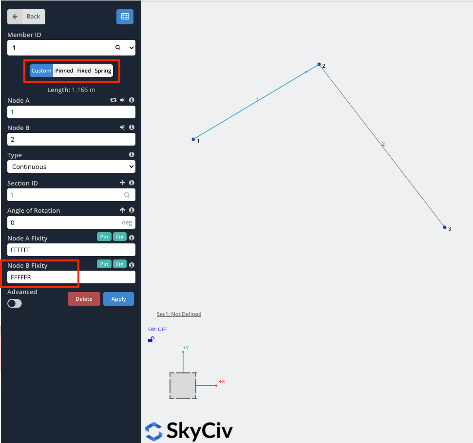
Για να καθορίσετε προσαρμοσμένες τιμές, βεβαιωθείτε ότι το Εθιμο Το κουμπί έχει επιλεγεί. Αυτό επιτρέπει την επεξεργασία των πεδίων τελικής σταθερότητας.
Πώς να πείτε τη σταθερότητα του τελικού μέλους ενώ κοιτάζετε στο χώρο του μοντέλου
Κατά τη μοντελοποίηση με τα μέλη, Είναι βολικό να γνωρίζετε τα μέλη’ τελική σταθερότητα χωρίς να χρειάζεται να κάνετε κλικ σε κάθε μέλος ξεχωριστά. Από προεπιλογή, όταν τα μέλη μοντελοποιούνται έχουν πλήρως σταθερές ακραίες σταθεροποιήσεις (FFFFFF). Το μέλος μοιάζει με μία γραμμή μεταξύ κόμβων:

Όταν απελευθερώνεται κάποιος από τους βαθμούς ελευθερίας, Το μέλος θα έχει μια μικρή κουκκίδα κοντά στο τέλος του μέλους (Όπως φαίνεται παρακάτω με κόκκινο χρώμα). Για παράδειγμα, για μέλη με καρφιτσωμένα άκρα στερέωσης (FFFRRR), Το μέλος θα μοιάζει με αυτό:

Περαιτέρω εξήγηση
Για περισσότερες πληροφορίες σχετικά με τις σταθερότητες των μελών, Το SkyCiv έχει ένα τεχνικό άρθρο (συμπεριλαμβανομένου ενός βίντεο) στο blog μας, εστιάζοντας Πώς να μοντελοποιήσετε τις σταθερότητες των μελών:
Παράδειγμα: Πώς να μοντελοποιήσετε τις συνδέσεις PIN ή τους μεντεσέδες
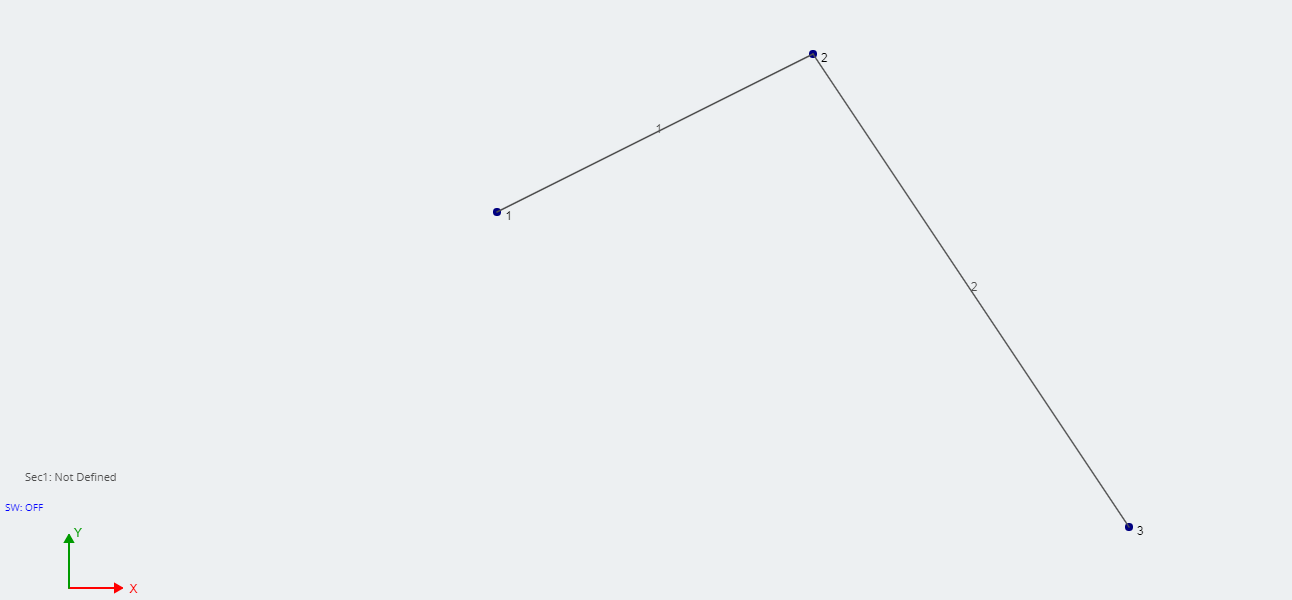
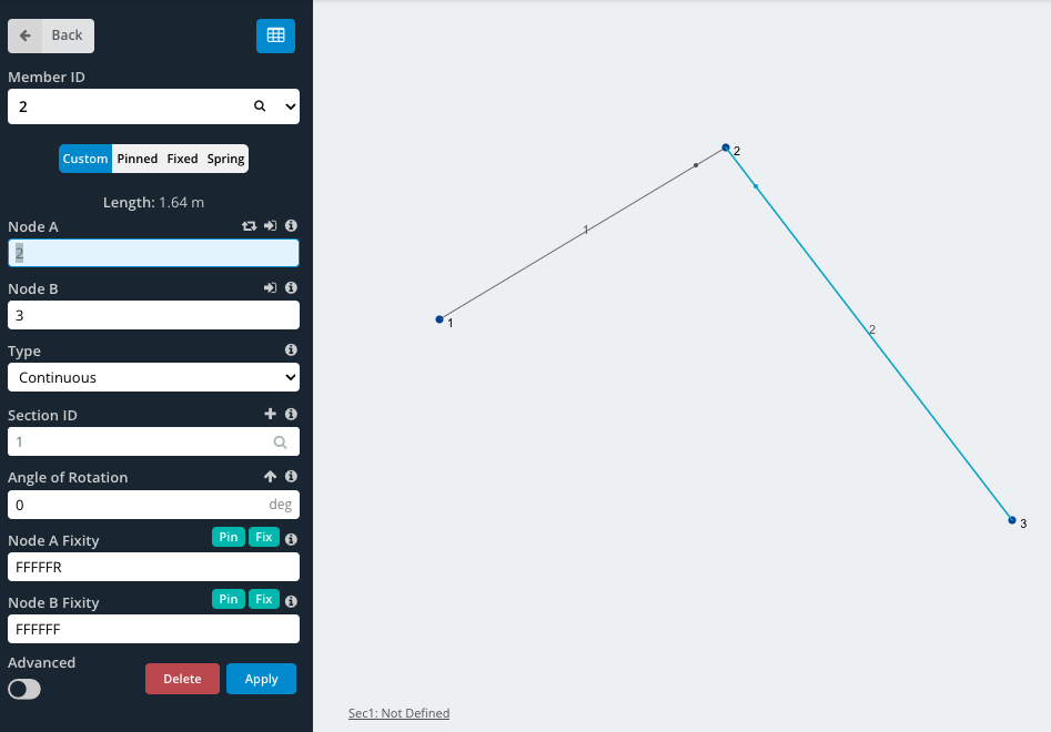
Σε αυτό το παράδειγμα, θα δημιουργήσουμε μια απλή σύνδεση pin, όπως μια άρθρωση. Ξεκινήστε δημιουργώντας 3 κόμβους και ένωση τους με 2 μέλη. Σε αυτό το παράδειγμα κόμβου, 2 θα είναι η άρθρωση.
Περισσότερες πληροφορίες
Για περισσότερες πληροφορίες, Το SkyCiv έχει μια περαιτέρω εξήγηση Πώς να μοντελοποιήσετε έναν μεντεσέ, Χρήση λογισμικού δομικής ανάλυσης.
βίντεο: Εξηγώντας βαθμούς κωδικών ελευθερίας και σταθερότητας