Ο σκοπός αυτού του άρθρου είναι να δείξει πώς το Ίδρυμα SkyCiv μπορεί να χρησιμοποιηθεί Ο σκοπός αυτού του άρθρου είναι να επεξηγήσει πώς μπορεί να χρησιμοποιηθεί το Ίδρυμα SkyCiv με ένα πραγματικό έργο. Αυτό περιλαμβάνει: τον υπολογισμό της ικανότητας επιπέδου υπηρεσίας για την πίεση, σταθερότητα του ποδιού, μέγεθος του ποδιού; και επίπεδο αντοχής για το πάχος και την ενίσχυση της θεμελίωσης. Ο σκοπός αυτού του άρθρου είναι να επεξηγήσει πώς μπορεί να χρησιμοποιηθεί το Ίδρυμα SkyCiv με ένα πραγματικό έργο, Ο σκοπός αυτού του άρθρου είναι να επεξηγήσει πώς μπορεί να χρησιμοποιηθεί το Ίδρυμα SkyCiv με ένα πραγματικό έργο.
Ιστορικό έργου
Αυτό το χαρακτηριστικό έργο σχεδιάστηκε και κατασκευάστηκε από BetaQuad Construction and Service Co., και βρίσκεται στο Central Luzon, Φιλιππίνες. Χρησιμοποιείται για την εμπορική παραγωγή τσιμέντου, έχοντας ημερήσια παραγωγική ικανότητα 30,000 μετρικούς τόνους. Το συνολικό αποτύπωμα του έργου κατά την κατασκευή ήταν περίπου 800 Μ2. Βλέπεται παρακάτω, το χαλύβδινο τμήμα της κατασκευής λειτουργεί ως πλαίσιο που αντιστέκεται στο πλευρικό φορτίο (3ΣΤ με ημιώροφο). Σε όλα αυτό το έργο έχει 43 απομονωμένες βάσεις που χρειάζονται για τη δομική μελέτη.
Η βάση του κώδικα σχεδίασης που εφαρμόστηκε για το σχέδιο του ιδρύματος ήταν το NSCP 2015. NSCP 2015 είναι παρόμοιο με το ACI 318-14 κώδικας , το οποίο ACI 318-14 είναι διαθέσιμη στην ενότητα σχεδίασης του ιδρύματος SkyCiv.
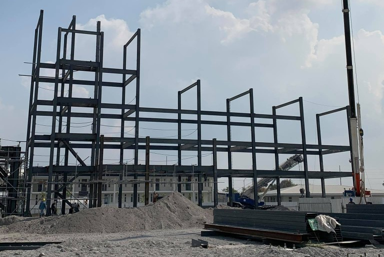
Φιγούρα 1 : Επί τόπου φωτογραφία του έργου κατά την κατασκευή
Μοντέλο και παράμετροι SkyCiv
Μοντελοποίηση της παραπάνω δομής στο SkyCiv Structural 3D πλατφόρμα σημαίνει ότι οι σχεδιαστές μπόρεσαν να επωφεληθούν από το διάφορα εργαλεία μοντελοποίησης που είναι διαθέσιμα για όλους τους χρήστες SkyCiv.
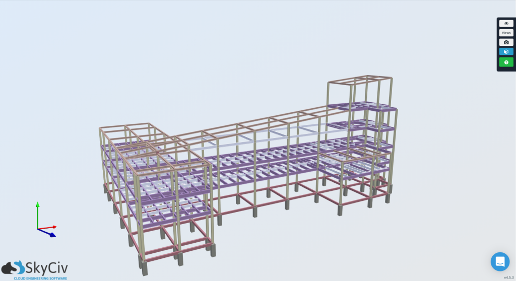
Φιγούρα 2 : 3D Απόδοση του δομικού τρισδιάστατου μοντέλου SkyCiv
Ο σκοπός αυτού του άρθρου είναι να επεξηγήσει πώς μπορεί να χρησιμοποιηθεί το Ίδρυμα SkyCiv με ένα πραγματικό έργο
Για σχέδιο βάσης, Οι πιο σημαντικές κτιριακές παράμετροι που απαιτούνται για τον σχεδιασμό απομονωμένων ποδιών θα είναι τα σεισμικά χαρακτηριστικά της τοποθεσίας, και τις ιδιότητες του υλικού της βάσης. Για την τοποθεσία αυτού του έργου στο Central Luzon, Φιλιππίνες, η αντίστοιχη σεισμική ζώνη είναι Σεισμική Ζώνη 4.
Ο σκοπός αυτού του άρθρου είναι να επεξηγήσει πώς μπορεί να χρησιμοποιηθεί το Ίδρυμα SkyCiv με ένα πραγματικό έργο, 20.68 MPa Ο σκοπός αυτού του άρθρου είναι να επεξηγήσει πώς μπορεί να χρησιμοποιηθεί το Ίδρυμα SkyCiv με ένα πραγματικό έργο 415 MPa χάλυβας οπλισμού αντοχής διαρροής. Είναι σημαντικό όταν περνάτε από ένα σχεδιασμό Foundation χρησιμοποιώντας την ενότητα SkyCiv Foundation Design, ή οποιοδήποτε λογισμικό, ότι αυτές οι ιδιότητες υλικού έχουν εισαχθεί σωστά, αλλιώς θα υπάρξουν διακυμάνσεις για το σχεδιασμό.
Γεωτεχνικές Συστάσεις
Τα περισσότερα έργα απαιτούν γεωτεχνικές εκθέσεις, που περιγράφουν τις ιδιότητες του εδάφους και τα γενικά χαρακτηριστικά της τοποθεσίας. Χρησιμοποιώντας τις γεωτεχνικές πληροφορίες που παρέχονται από τον γεωτεχνικό μηχανικό αυτού του έργου, ο ιστότοπος βρέθηκε να έχει τις ακόλουθες ιδιότητες:
Ύψος εδάφους = 2 μέτρα
Φέρουσα Ικανότητα εδάφους = 192 KPa.
Βάρος μονάδας εδάφους = 16 kN / m3
Αυτά τα χαρακτηριστικά απαιτούνται κατά το σχεδιασμό οποιουδήποτε τύπου θεμελίωσης, και επομένως θα πρέπει να καταγραφεί για μεταγενέστερη εισαγωγή της ενότητας SkyCiv Foundation.
Φόρτωση συνδυασμών
Το SkyCiv Foundation Design Module μπορεί να εκτελέσει τους βασικούς συνδυασμούς φόρτωσης και αναπαρίσταται ως Service και Factored Loads. Επίσης, η μονάδα σχεδίασης θα εξετάσει αυτόματα τις σεισμικές παραμέτρους κατά τα φορτία σεισμού (μι) έχουν οποιαδήποτε τιμή στην είσοδο.
Για Γεωτεχνικό Σχεδιασμό (Επίπεδο εξυπηρέτησης):
Οι ισχύοντες συνδυασμοί φορτίων για γεωτεχνικό σχεδιασμό, που ισχύουν και για τα δύο ASCE 7-10 και NSCP 2015 σχεδιαστικοί κώδικες, είναι οι ακόλουθες:
[1] ρε + μεγάλο
[2] ρε + μεγάλο + Ε/1.4
[3] ρε + Ε/1.4
Για Στατική Μελέτη (Factored Επίπεδο):
Οι συνδυασμοί φορτίου εφαρμογής για δομικό σχεδιασμό που ισχύουν και για τα δύο ASCE 7-10 και NSCP 2015 Οι κωδικοί σχεδιασμού είναι οι ακόλουθοι:
[1] 1.4ρε
[2] 1.2ρε + 1.6μεγάλο
[3] 1.2ρε + 1.0μι + 1.0μεγάλο
[4] 0.9ρε + 1.0μι
Σχεδιασμός Θεμελίων
Η πραγματική ροή εργασίας του σχεδιασμού των θεμελίων έρχεται αμέσως μετά την ολοκλήρωση της δομικής ανάλυσης της δομής μας, όπου μπορούμε να ερμηνεύσουμε τις αντιδράσεις δομών.
Αποτελέσματα δομικής ανάλυσης & Αντιδράσεις
Πριν πάτε στην ενότητα του Foundation για να σχεδιάσετε τις βάσεις του έργου, μπορεί να αυτοματοποιήσει τους συνδυασμούς φορτίων ανά AS/NZS1170. Αυτές οι αντιδράσεις προσδιορίστηκαν από μια δομική ανάλυση. Χρήση αποτελεσμάτων φακέλου, λήφθηκαν οι χειρότερες περιπτώσεις για κάθε ίδρυμα. λήφθηκαν οι χειρότερες περιπτώσεις για κάθε ίδρυμα.
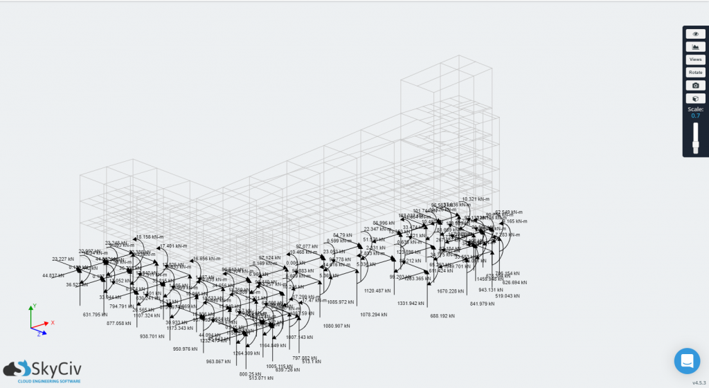
Εικόνα 3-α: Αντιδράσεις βάσης στήλης από το δομικό τρισδιάστατο μοντέλο
Σε Εικόνα 3-α, το S3D παρουσιάζει τα φορτία αντίδρασης που μπορούν να εξαχθούν και να εισαχθούν στο SkyCiv Foundation Design Module.
Εισαγωγή & Έξοδος της ενότητας Foundation
Με τις δυνάμεις καταγεγραμμένες, η ενότητα SkyCiv Foundation μπορεί να χρησιμοποιηθεί για την ανάλυση και τον έλεγχο των σχεδίων αυτών των ποδιών. Η ενότητα επιτρέπει στους μηχανικούς να προσθέσουν όσα θεμέλια απαιτούνται για το έργο. Έτσι σε αυτή την περίπτωση, οι μηχανικοί σχεδίασαν και έλεγξαν το 43 βάσεις ανεξάρτητα. Εικόνα 3-β δείχνει τη διεπαφή χρήστη και την παρουσίαση όταν εξετάζονται περισσότερα από ένα θεμέλια για σχεδιασμό.
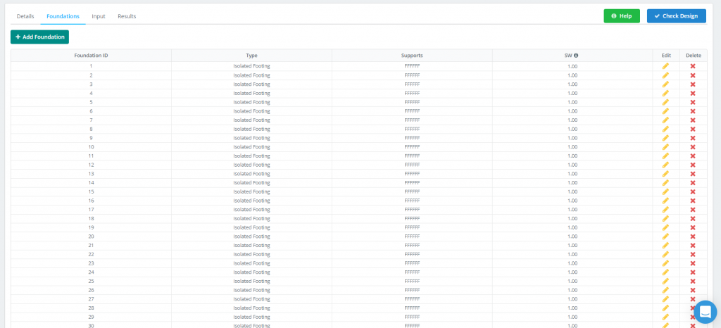
Εικόνα 3-β: Καρτέλα Σχέδιο Θεμελίωσης
Προχωρώντας παραπέρα, κάθε σχέδιο βάσης ενσωματώνει ένα εύχρηστο, γραμμική ροή εργασίας, όπου μπορούν να εισαχθούν όλες οι καταγεγραμμένες πληροφορίες από τα προηγούμενα βήματα.
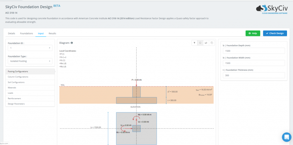
Εικόνα 3-γ: Διεπαφή χρήστη Μονάδας Σχεδιασμού Θεμελίωσης
Μόλις καθοριστούν οι απαιτήσεις σχεδιασμού και εισαχθούν οι ιδιότητες και τα φορτία του υλικού, η βάση είναι έτοιμη για σχεδιασμό. Η παρουσίαση του σχεδίου προκύπτει αφού κάνετε κλικ στο Ελέγξτε το σχέδιο το κουμπί φαίνεται στο Εικόνα 3-δ. Αυτά τα αποτελέσματα είναι εύκολα κατανοητά, καθώς παρουσιάζονται ως λόγοι ενότητας. Αυτές οι αναλογίες παρουσιάζουν την Έμπειρη/Χωρητικότητα για κάθε μεμονωμένη οριακή κατάσταση. Όταν κάποιος βρεθεί να έχει τελειώσει 1.0, ο Κατάσταση του ποδιού θα γίνει κόκκινο και θα δείξει “Αποτυγχάνω”. Σε διαφορετική περίπτωση, αυτό το κελί θα είναι πράσινο και θα εμφανίζεται “Πέρασμα”. Αυτό διευκολύνει τον γρήγορο έλεγχο των θεμελίων που μπορεί να χρειαστούν μικροαλλαγές ή περισσότερη δουλειά στη διαδικασία σχεδιασμού.

Εικόνα 3-δ: Δείγματα Αποτελεσμάτων Σχεδιασμού
Όπως αναφέρεται στο Εικόνα 3-δ, οι πέντε διαφορετικές οριακές καταστάσεις που ελέγχονται κατά τη διάρκεια του σχεδιασμού είναι:
- Μέγεθος ποδιού
- Σταθερότητα όπως ανατροπή και ολίσθηση
- Μονόδρομη διάτμηση
- Διάτμηση διπλής κατεύθυνσης
- Κάμψη
Για να εμβαθύνουμε στις αναλογίες ενότητας κάθε οριακής κατάστασης, οι μηχανικοί μπορούν να δουν τις Αναφορές Σχεδιασμού Θεμελίωσης, τα οποία είναι προσβάσιμα για κάθε ίδρυμα. Αυτές οι αναφορές ανοίγουν το μαύρο κουτί του λογισμικού δομικής μηχανικής παρέχοντας διαγράμματα και λεπτομερείς υπολογισμούς με τα χέρια μαζί σε ένα επαγγελματικό PDF που μπορεί να εξαχθεί και να χρησιμοποιηθεί για χρήση έργου. Βλέπω Εικόνα 3-ε παρακάτω για να δείτε πώς φαίνεται μία από αυτές τις αναφορές:
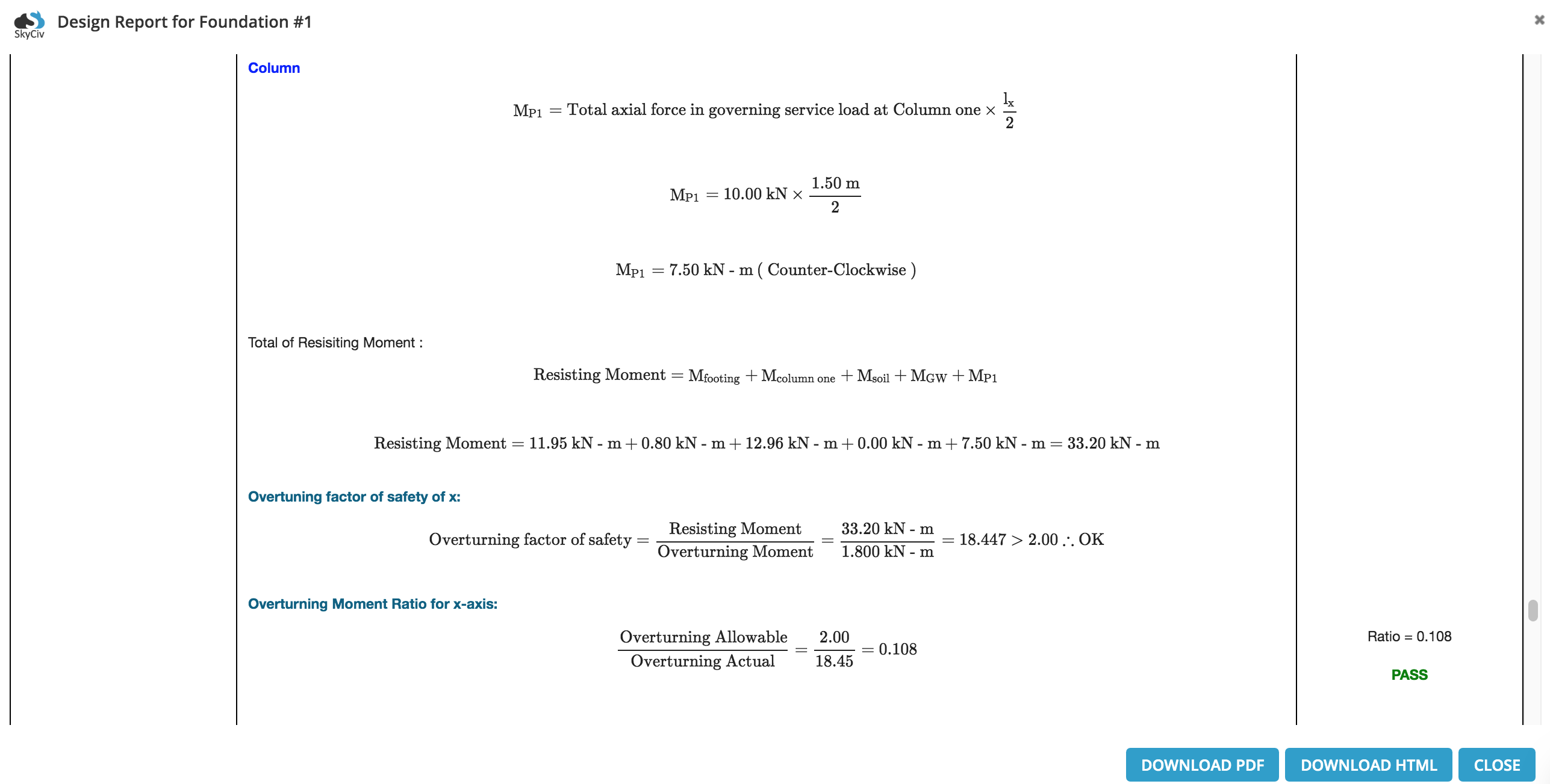
Εικόνα 3-ε: Παράδειγμα απόσπασμα από αναλυτική έκθεση Foundation Design

Albert Pamonag, M.Eng
Δομικός μηχανικός, Ανάπτυξη προϊόντων