Παράδειγμα Επισκόπηση
Σε αυτό το παράδειγμα θα μάθετε τα βασικά βήματα της δημιουργίας μοντέλου δοκού, πλέγμα, υλικά, οριακές συνθήκες και εισροές φορτίων. Θα πραγματοποιηθεί ανάλυση χρησιμοποιώντας γραμμική στατική και γραμμική ανάλυση λυγισμού.
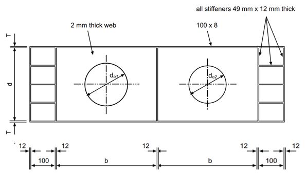
Το παράδειγμα που παρουσιάζεται σε αυτό το σεμινάριο είναι η δοκός με συνολικό μήκος 1700 mm και βάθος 500 χιλ. Ο ιστός έχει πάχος 2 mm και υπάρχουν δύο ανοίγματα ιστού (κυκλικό σχήμα) με διαμέτρους 400 mm και 350 χιλ. Οι επάνω και κάτω φλάντζες έχουν πλάτος 100 mm και πάχος 8 χιλ. Ο ιστός της δοκού σκληρύνεται και από τις δύο πλευρές με κατακόρυφα ενισχυτικά και διαμήκη ενισχυτικά (στα άκρα). Τα κατακόρυφα ενισχυτικά δημιουργούν δύο κύρια φύλλα μήκους 750 χιλ. Όλα τα ενισχυτικά έχουν πλάτος 50 mm και πάχος 12 χιλ. Η δοκός φορτίζεται από μια συγκεντρωμένη κατακόρυφη δύναμη που βρίσκεται στην κορυφή των κατακόρυφων ενισχυτικών στη μέση, και η δοκός έχει δύο στηρίγματα κάτω από το δεύτερο και το τέταρτο κάθετο ενισχυτικό.
Η δοκός είναι κατασκευασμένη από χάλυβα με τάση διαρροής 230 MPa για το διαδίκτυο, και 245 MPa για άλλα στοιχεία.
Το τρέχον παράδειγμα αντιπροσωπεύει το πειραματικό τεστ από το χαρτί “Απόλυτη συμπεριφορά διάτρητων δοκών από χάλυβα που υπόκεινται σε φόρτιση διάτμησης. Alireza Bahrami, Mahdi Najarnasab. The Open Construction and Building Technology Journal”.
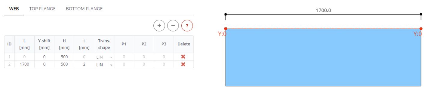
Βήμα 1. Ιστός
Στον πίνακα Web ορίστε το web με μήκος (μεγάλο) 1700 χιλ, βάθος (Η) 500 mm και πάχος (τ) 2 χιλ.
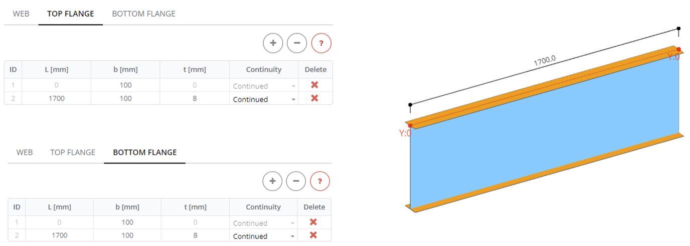
Βήμα 2. Πέλματα
Στο πλαίσιο Flange ορίστε τις επάνω και κάτω φλάντζες σε όλο το μήκος του ιστού (μεγάλο) 1700 χιλ, με πλάτος έναρξης και λήξης (σι) 100 mm και πάχος (τ) 8 χιλ
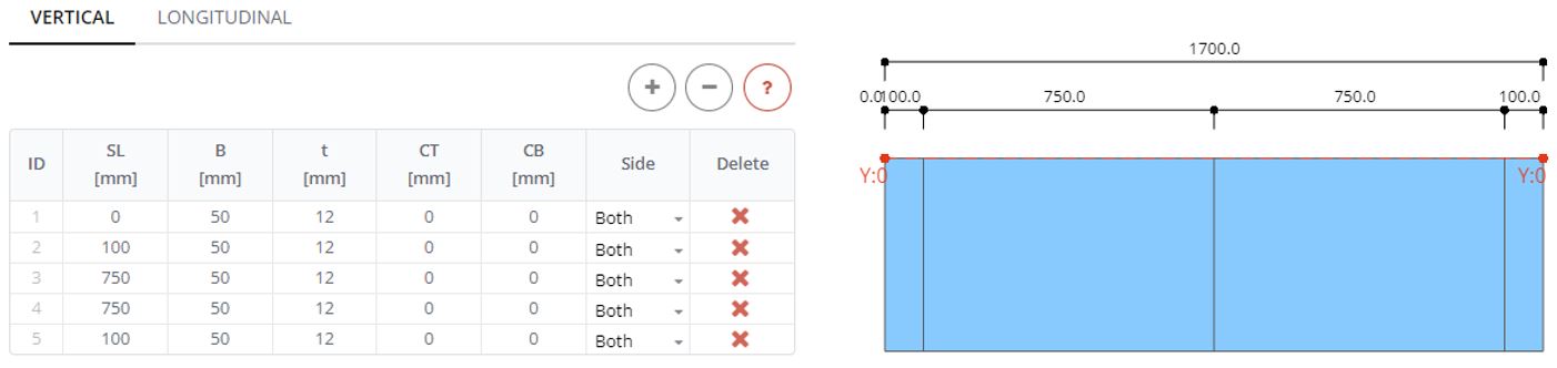
Βήμα 3. Κάθετα ενισχυτικά
Στον πίνακα κατακόρυφο ενισχυτή ορίστε ενισχυτικά με ανοίγματα (SL) 100, 750, 750 και 100 mm από την αριστερή πλευρά της δοκού. Καθορίστε τα όλα με το πλάτος (σι) 50 mm και πάχος (τ) 12 χιλ.
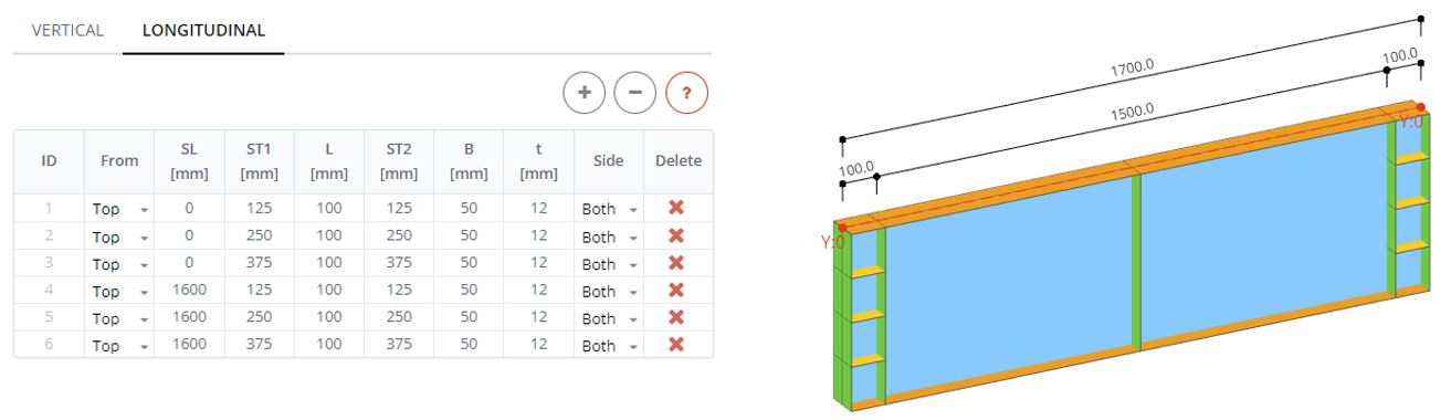
Βήμα 4. Διαμήκεις ενισχυτές
Στον πίνακα Διαμήκης ακαμψίας ορίστε 6 ενισχυτικά. Στην αρχή της δοκού (SL: 0 χιλ) καθορίζω 3 ενισχυτικά με μήκος (μεγάλο) 100 mm και θέση από πάνω (ST1, ST2) 125, 250, και 375 χιλ. Τα άλλα τρία ενισχυτικά ξεκινούν από απόσταση (SL) 1600 χιλ. Πλάτος (σι) και πάχος (τ) είναι τα ίδια με τα κατακόρυφα ενισχυτικά.
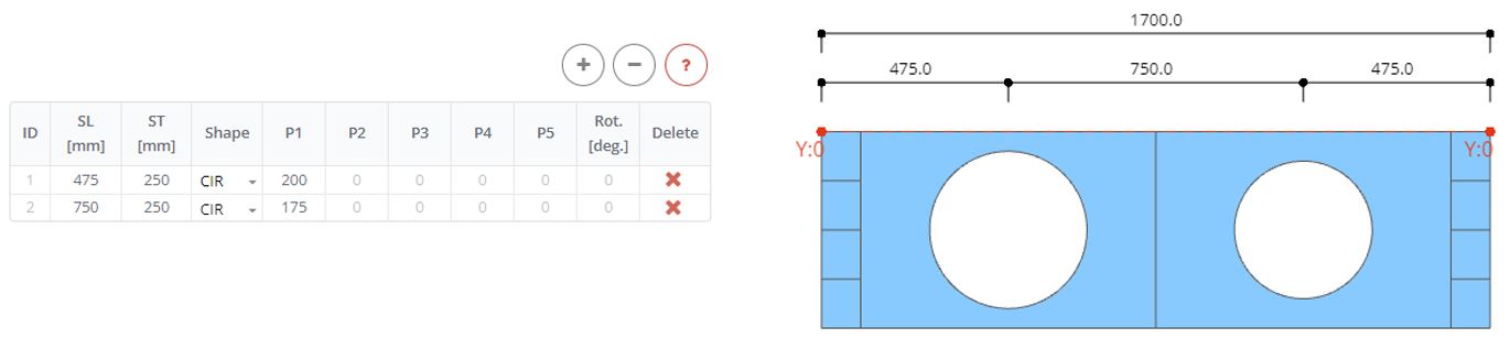
Βήμα 5. Ανοίγματα Ιστού
Στον πίνακα ανοίγματα Ιστού ορίστε δύο ανοίγματα. Και τα δύο έχουν σχήματα CIR (κυκλικό σχήμα) με ακτίνα (Ρ1) 200 και 175 χιλ. Ένα άνοιγμα είναι διευθετημένο στο (SL) 475 mm από τα αριστερά, και το δεύτερο στο 750 χιλ. Το κέντρο ανοίγματος μετατοπίζεται από την κορυφή (ST) επί 250 χιλ.
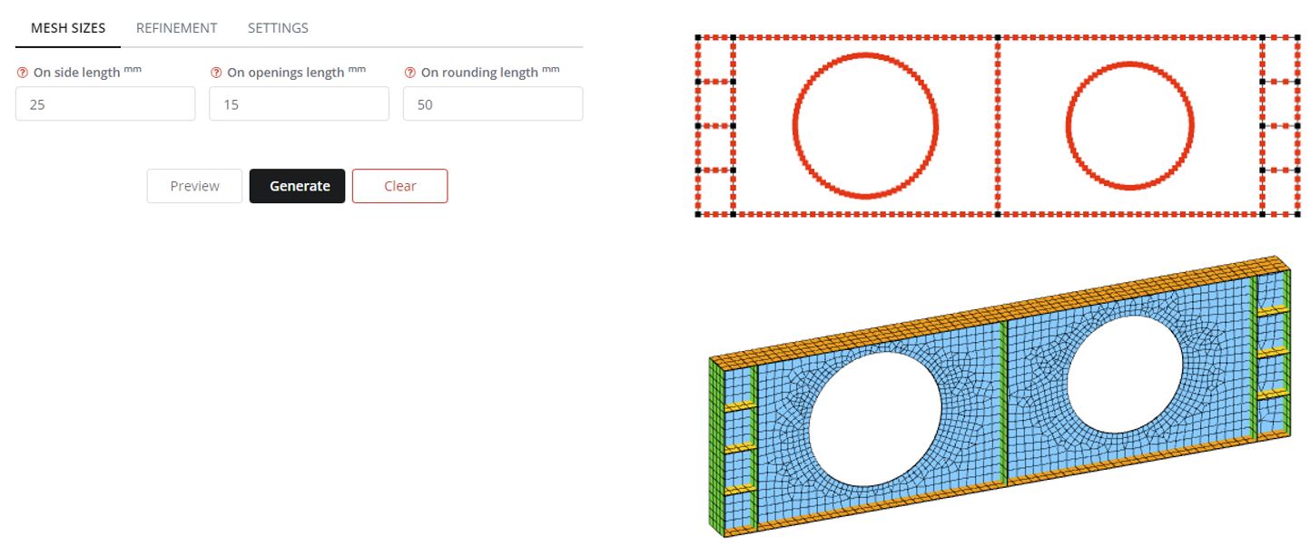
Βήμα 6. Πλέγμα
Στον πίνακα Mesh ορίστε τα μεγέθη στοιχείων πλέγματος στο μήκος της πλευράς ως 25 χιλ, και στο μήκος ανοίγματος ως 15 χιλ. ο 25 Το μήκος πλευράς mm θα εφαρμοστεί για τον ιστό, πέλματα, και ενισχυτικά άκρα. ο 15 Το μήκος ανοίγματος mm θα εφαρμοστεί για τις ανοιγόμενες άκρες. Κάντε κλικ στο κουμπί Προεπισκόπηση για να δείτε την πιθανή κατανομή κόμβων FE. Κάντε κλικ στο κουμπί Δημιουργία για να δημιουργήσετε το πλέγμα FE για ανάλυση.
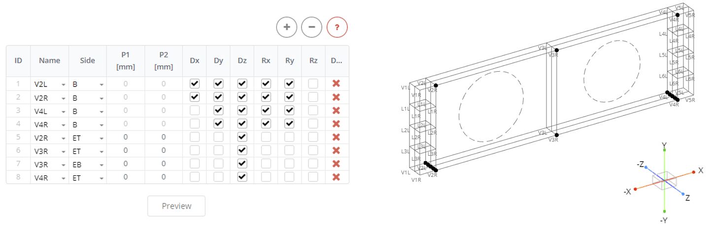
Βήμα 7. Όρια
Στον πίνακα Boundary Stiffeners ορίστε περιορισμούς για τη δοκό. Εδώ ένας πείρος και ένα στηρίγματα κυλίνδρων βρίσκονται στο κάτω μέρος του ενισχυτή 2 και ενισχυτικό 4. Ορίστε τις δύο πρώτες σειρές στον πίνακα ως το αριστερό και το δεξί μέρος του ενισχυτικού 2 (Ονομα: V2L, V2R). Καθορίστε την πλευρά των ενισχυτικών που πρέπει να περιοριστεί (σι). Ακολουθήστε τον καθολικό άξονα για να ορίσετε περιορισμούς για τους κόμβους (Το καρφιτσωμένο στήριγμα έχει μόνο μία απελευθέρωση για περιστροφή γύρω από τον άξονα z). Οι άλλες δύο σειρές στον πίνακα αντιστοιχούσαν στο στήριγμα του κυλίνδρου, κάτω από τα μέρη του κατακόρυφου ενισχυτή 4 (Ονομα: V4L, V4R). Η δοκός δεν έχει πλευρικές μεταφράσεις. Ορίστε το επόμενο 4 σειρές στον πίνακα για τη δεξιά πλευρά του ενισχυτή V2R, V3R, V4R, επιλέξτε ET και EB, και ορίστε περιορισμούς μόνο κατά μήκος του άξονα Z. Κάντε κλικ στο κουμπί Προεπισκόπηση για να δείτε τους κόμβους με περιορισμούς.
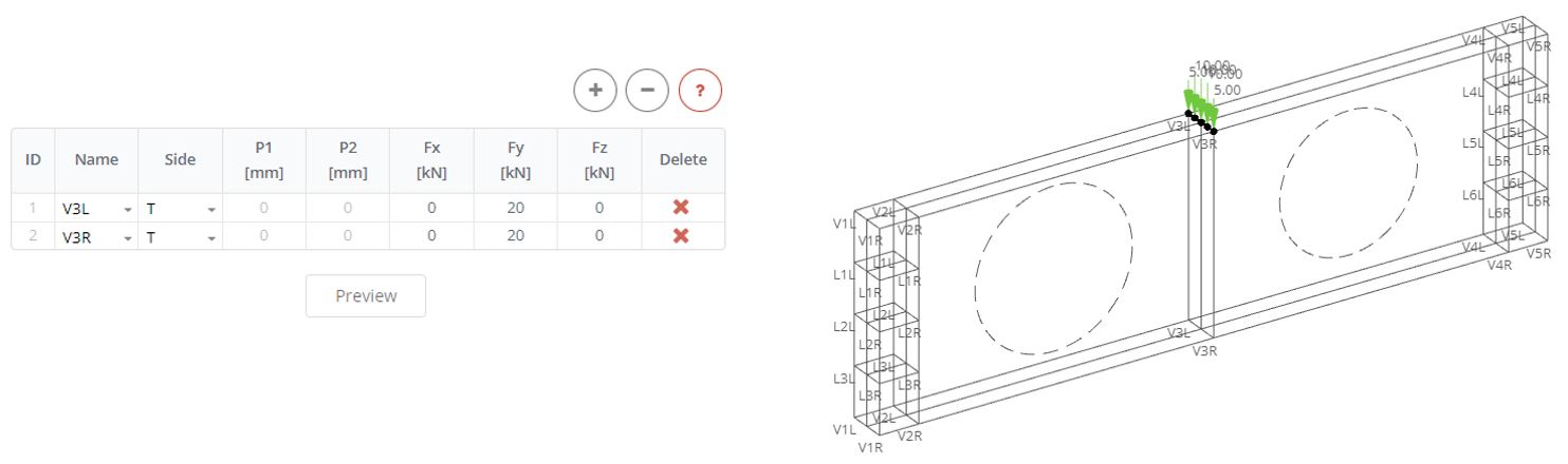
Βήμα 8. Φορτία
Στον πίνακα Stiffener Loads ορίστε το συγκεντρωμένο φορτίο στο μέσο της δοκού. Το φορτίο έχει αξία 40 kN και θα εφαρμοστεί πάνω από δύο κατακόρυφα ενισχυτικά. Στον πίνακα ορίστε δύο σειρές, επιλέξτε αριστερά και δεξιά μέρη του ενισχυτή 3 (V3L, V3R). Εφαρμόστε το μισό φορτίο (Fz: 20 ΚΝ) στην επάνω πλευρά (Τ) κάθε τμήματος του ενισχυτικού. Κάντε κλικ στην Προεπισκόπηση για να δείτε πώς κατανέμεται το φορτίο στους κόμβους FE.
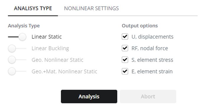
Βήμα 9. Ανάλυση
Επιλέξτε Linear Static στον πίνακα Analysis Type και κάντε κλικ στο κουμπί Analysis.
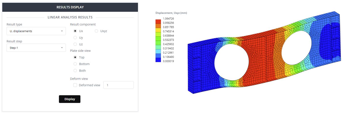
Βήμα 10. Αποτελέσματα μετατοπίσεων
Στον πίνακα Αποτελέσματα επιλέξτε τον τύπο αποτελέσματος από την αναπτυσσόμενη λίστα. Εμφανίστε μια παραμορφωμένη άποψη του μοντέλου με την κλιμάκωση παραμόρφωσης.
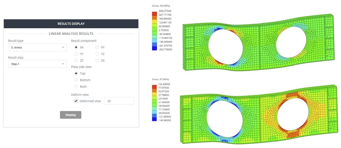
Βήμα 11. Αποτελέσματα άγχους
Επιλέξτε τύπο αποτελέσματος 'S, στρες» για να ελέγξετε το περίγραμμα κατανομής τάσεων. Επιλέξτε διαφορετικά στοιχεία τάσης και εμφανίστε το περίγραμμα. Το φυσιολογικό άγχος (ΧΧ) αξία είναι 308 MPa και υπερβαίνει την τάση διαρροής του ιστού 230 MPa. Αυτό δείχνει την εμφάνιση πλαστικών ζωνών καταπόνησης στον ιστό. Στο επόμενο σεμινάριο αυτή η πλαστικότητα θα διερευνηθεί λεπτομερέστερα για αυτήν τη δοκό.
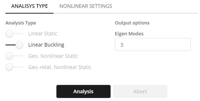
Βήμα 12. Ανάλυση Γραμμικής Λυγισμού
Τώρα διερευνήστε τα σχήματα γραμμικού λυγισμού και τις κρίσιμες δυνάμεις λυγισμού της δοκού. Επιλέξτε «Γραμμικός λυγισμός’ στον πίνακα Τύπος ανάλυσης. Επιλέξτε τον απαραίτητο αριθμό σχημάτων λυγισμού, ή "Δικοί τρόποι λειτουργίας". Τυπικά, για τον τρέχοντα τύπο ανάλυσης δέσμης, 3-5 οι λειτουργίες είναι αρκετές. Κάντε κλικ στο κουμπί Ανάλυση.
Βήμα 13. Αποτελέσματα λυγισμού
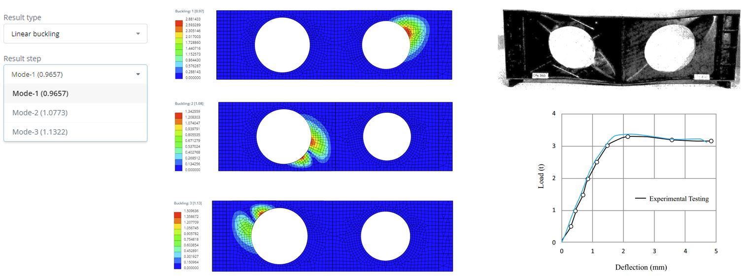
Στον πίνακα αποτελεσμάτων Γραμμικού λυγισμού μπορείτε να επιλέξετε τη λειτουργία αποτελέσματος. Εδώ είναι τα 3 τρόποι λειτουργίας με τους αντίστοιχους συντελεστές φορτίου λυγισμού. Εάν πολλαπλασιαστεί ο συντελεστής με την εφαρμοσμένη τιμή φορτίου, θα λάβετε την κρίσιμη γραμμική δύναμη λυγισμού. Για παράδειγμα, με την εφαρμοσμένη μας δύναμη του 40 kN το κρίσιμο φορτίο λυγισμού θα είναι Fcr = 0.965 Χ 40 = 38.6 ΚΝ. Στην πράξη, αυτό σημαίνει ότι εάν εφαρμοστεί αυτό το κρίσιμο φορτίο στην κατασκευή, τότε η κατασκευή γίνεται ασταθής ως προς τη σταθερότητα γραμμικού λυγισμού. Τα σχήματα λυγισμού φαίνονται αφού κάνετε κλικ στο κουμπί Εμφάνιση. Τα πιθανά σχήματα λυγισμού βρίσκονται κυρίως γύρω από τον ιστό. Αυτό το είδος λυγισμού ονομάζεται τοπικός λυγισμός. Χρησιμοποιώντας αυτά τα αποτελέσματα μπορεί να επιβεβαιωθεί ότι η κατασκευή δεν έχει αρκετή χωρητικότητα για αυτό το εφαρμοζόμενο φορτίο. Αυτό αποδεικνύεται και από τα αποτελέσματα των πειραματικών δοκιμών. Από το πείραμα η κρίσιμη δύναμη είναι παρακάτω 40 ΚΝ.
SkyCiv Beam
Απολαύστε γρήγορη και ακριβή ανάλυση των δομών δοκών με το λογισμικό SkyCiv Beam! Δοκιμάστε το τώρα με το Free Beam Tool μας, εξοπλισμένο με χαρακτηριστικά όπως αριθμομηχανή ροπής κάμψης, αριθμομηχανή διατμήσεων και ροπών, αριθμομηχανή αντίδρασης δέσμης, και πολλα ΑΚΟΜΑ. Πάρτε μια γεύση από το τι μπορεί να κάνει το λογισμικό μας για εσάς σήμερα!